Table of Contents
Advertisement
Quick Links
Advertisement
Table of Contents

Subscribe to Our Youtube Channel
Related Manuals for Hubbell M-7679 R-PAC


Summary of Contents for Hubbell M-7679 R-PAC
- Page 1 Instruction Book M‑7679 R‑PAC...
- Page 2 No Warranty. Software is provided "AS IS". No implied warranties available including merchantability & fitness for a particular purpose. Beckwith Electric, a subsidiary of Hubbell Power Systems, Inc., is solely responsible for determining the appropriateness of using or redistributing the work and assumes any risks associated with its exercise of permissions under this License.
- Page 3 M‑7679 R‑PAC Protection, Automation and Control System for Recloser, Switch, Sectionalizer and Advanced Distribution Automation Applications ALARM A B C SELECT SETTINGS AC / BATTERY PHASE Protection and Control ALT SETTINGS • Over 30 Protection Elements for optimal protection of N / G / SEF Power Distribution Systems RESET...
- Page 4 Port 1 Front Port IRIG-B Port 2 Port 3 Port 4 TIA-232 Type B USB Ethernet Ethernet TIA-232 Fiber Optic Fiber Optic TIA-485 SD Card TIA-485 Serial Fiber Serial Fiber Copper Copper Figure 1 M-7679 R-PAC One-Line Functional Diagram –2–...
- Page 5 M‑7679 R‑PAC – Specification Standard Control Features • PORT 1 – Rear TIA-232 • Protocols Supported: • Over 30 protection functions – MODBUS • Horizontal or Vertical Mounting – DNP3.0 SAv2 • 50 Hz or 60 Hz Frequency – Smart P2P (Peer-To-Peer)▲ •...
- Page 6 M‑7679 R‑PAC – Specification M‑7679 Mounting Options M‑2400 Series Adapters The M-2400 Series Adapters allow a simple, easy installation of the M-7679 into an existing cabinet to retrofit the following controls: • M-2406 to retrofit the Eaton Cooper Form 6 (for 14-Pin or 19-Pin reclosers) •...
- Page 7 M‑7679 R‑PAC – Specification External Connections The possible connections for the M-7679 R-PAC are shown in Figure CAUTION: Any TB3 receptacle that is NOT GREEN indicates that a Low Voltage Power Supply is ▲ installed in the unit. IN 1...
- Page 8 M‑7679 R‑PAC – Specification PROTECTIVE FUNCTIONS Device Setpoint Number Function Ranges Increment Accuracy † Sync Check Reference Phase A/B/C – – Undervoltage Permission Dead Line/Dead Bus Yes/No – – Dead Line/Live Bus Yes/No – – Live Line/Dead Bus Yes/No – –...
- Page 9 M‑7679 R‑PAC – Specification PROTECTIVE FUNCTIONS (cont.) Device Setpoint Number Function Ranges Increment Accuracy † Negative Sequence Overcurrent (#1 to #5 Elements) Definite Time Pickup 1 A CT (or 5 mA CT) 0.02 to 20.00 A 0.01 A ± 0.02 A or ± 3% 5 A CT 0.10 to 100.00 A 0.01 A...
- Page 10 M‑7679 R‑PAC – Specification PROTECTIVE FUNCTIONS (cont.) Device Setpoint Number Function Ranges Increment Accuracy † Broken Conductor Detection Pickup (I2/I1 ratio) 1 to 100% ± 3% Time Delay 0.00 to 600.00 s 0.01 s ± 0.01 s or ± 1% Minimum I2 Level 0.02 to 20.00 A 0.01 A...
- Page 11 M‑7679 R‑PAC – Specification PROTECTIVE FUNCTIONS (cont.) Device Setpoint Number Function Ranges Increment Accuracy † Instantaneous/Definite Time Overcurrent (#1 to #5 Elements) Phase Instantaneous/Definite Time Overcurrent Pickup 1 A CT (or 5 mA CT) 0.02 to 20.00 A 0.01 A ±...
- Page 12 M‑7679 R‑PAC – Specification PROTECTIVE FUNCTIONS (cont.) Device Setpoint Number Function Ranges Increment Accuracy † Inverse Time Overcurrent (#1 to #5 Elements) Phase Inverse Time Overcurrent with Voltage Control/Restraint Pickup 1 A CT (or 5 mA CT) 0.02 to 3.20 A 0.01 A ±...
- Page 13 M‑7679 R‑PAC – Specification PROTECTIVE FUNCTIONS (cont.) Device Setpoint Number Function Ranges Increment Accuracy † Overvoltage Phase Overvoltage (#1 to #4 Elements) / 3 Phase Undervoltage (#5 to #8 Elements) Pickup 10.00 to 300.00 V 0.01 V ± 0.2 V or ± 0.5% Definite Time 0.00 to 600.00 s 0.01 s...
- Page 14 M‑7679 R‑PAC – Specification PROTECTIVE FUNCTIONS (cont.) Device Setpoint Number Function Ranges Increment Accuracy † Directional Overcurrent (#1 to #5 Elements) Phase Directional Overcurrent Operating Current Phase Current Phase Polarization Voltage Residual Directional Overcurrent Operating Current Phase Polarization Voltage Ground Directional Overcurrent Operating Current Phase Polarization Voltage Negative Sequence Directional Overcurrent...
- Page 15 M‑7679 R‑PAC – Specification PROTECTIVE FUNCTIONS (cont.) Device Setpoint Number Function Ranges Increment Accuracy † Directional Instantaneous/Definite Time Overcurrent (Cont.) 67P, 67N, 67G, 67Q Settings (Continued) Inverse Time: Pickup 1 A CT / 5 mA CT/ 1 A Gnd CT 0.02 to 3.20 A 0.01 A ±...
- Page 16 M‑7679 R‑PAC – Specification PROTECTIVE FUNCTIONS (cont.) Device Setpoint Number Function Ranges Increment Accuracy † Recloser Relay Three-Phase Ganged or Optional Independent Phase Operation: Ground Precedence Yes/No Sequence Coordination Active For Trips None/1/2/3 – – Maximum Number of Phase Trips 1/2/3/4/5 –...
- Page 17 M‑7679 R‑PAC – Specification PROTECTIVE FUNCTIONS (cont.) Device Setpoint Number Function Ranges Increment Accuracy † Frequency (#1 to #8 Elements) Pickup 40.00 to 65.00 Hz 0.01 Hz ± 0.02 Hz Definite Time 0.00 to 600.00 s 0.01 s ± 0.01 s or ± 1% Hysteresis 0.0 to 1.0 Hz 0.1 Hz...
- Page 18 M‑7679 R‑PAC – Specification PROTECTIVE FUNCTIONS (cont.) Device Setpoint Number Function Ranges Increment Accuracy † Inrush Harmonic Restraint Inrush Harmonic Pickup 0.1 to 100% 0.1% ± 1% Inrush Harmonic Dropout 0.1 to 100% 0.1% ± 1% Inrush Active Time 0.01 to 600.00 s 0.01 s ±...
- Page 19 M‑7679 R‑PAC – Specification OPTIONAL PROTECTIVE FUNCTIONS Device Setpoint Number Function Ranges Increment Accuracy † Sensitive Ground Instantaneous/Definite Time Overcurrent (#1 to #5 Elements) Sensitive Ground Pickup 1 mA Gnd CT 0.010 to 0.320 A 0.001 A (TBD) 10 mA Gnd CT 0.001 to 0.160 A 0.001 A (TBD)
- Page 20 M‑7679 R‑PAC – Specification OPTIONAL PROTECTIVE FUNCTIONS (cont.) Device Setpoint Number Function Ranges Increment Accuracy † Sensitive Ground Inverse Time Overcurrent (#1 to #5 Elements) Phase Polarization Voltage – – Enabled Direction No-Direction/Directional – – Minimum Polarization Voltage (% of nominal voltage) 2.0 to 10.0 % 0.1% ±...
- Page 21 M‑7679 R‑PAC – Specification OPTIONAL PROTECTIVE FUNCTIONS Device Setpoint Number Function Ranges Increment Accuracy † Switch/Sectionalizer Three-Phase Ganged (Independent Phase Operation) SECT Fault Current Detection Function Element 1, 2, 3, 4, 5 50P, 50N, 50G/GS, 46DT – – Trigger Fault Current Only/ –...
- Page 22 M‑7679 R‑PAC – Specification OPTIONAL PROTECTIVE FUNCTIONS (cont.) Device Setpoint Number Function Ranges Increment Accuracy † Distribution Automation Package (includes 79, SW/SECT, Loop Scheme) Three‑Phase Ganged or Independent Phase Operation Loop Scheme – Three-Phase Ganged or Independent Phase Operation Loop Scheme Application Sectionalizing Recloser, –...
- Page 23 M‑7679 R‑PAC – Specification OPTIONAL PROTECTIVE FUNCTIONS (cont.) Device Setpoint Number Function Ranges Increment Accuracy † Distribution Automation Package (includes 79, SW/SECT, Loop Scheme) Three‑Phase Ganged or Independent Phase Operation Loop Scheme (continued) Tie Recloser: Dead Line Sensing: (3 Phase Undervoltage) Pickup –...
- Page 24 Phase Capable reclosers. Newer Independent Phase Capable reclosers provide the option to utilize one or two poles. The M-7679 R-PAC can be used to operate a recloser on an unbalanced system, and is fully configurable to match the desired operational needs. One pole operation provides protection and control features specific to a single phase application.
- Page 25 All Neutral (N), Ground (G) / Ground Sensitive (GS) functions are not available. Ground current connections (I ) require three phases. Source M-7679 R-PAC (Option P – DA Package Single Phase/Two Phase) Protection, Automation and Control System for Recloser, Switch, Sectionalizer and Advanced Distribution Automation Applications...
- Page 26 The settings for the different functions can be accomplished by using the IPScom S-7600 Communications Software or the front panel pushbuttons. For convenience and security, the M-7679 R-PAC offers an SD card reader. Programming can be done in the office and settings can be loaded using an SD card thus minimizing the time a user needs to spend in front of the control.
- Page 27 M‑7679 R‑PAC – Specification Reclosing Operation When there is any breaker open operation due to a fault, the relay will close the breaker automatically without user intervention. The Reclosing Operation is achieved using the 79 function in conjunction with overcurrent functions (i.e.
- Page 28 M‑7679 R‑PAC – Specification METERING ACCURACIES Analog sources used for measurement traceable to NIST Standards, with certifications on file. VOLTAGE ACCURACY Fundamental Metering Magnitude Phase Angle Voltage Range ± 0.04% ± 0.3° (0.167-10.0) Voltage Range ± 0.04% ± 0.7° (5.0-300.0) OPEN DELTA ±...
- Page 29 M‑7679 R‑PAC – Specification METERING ACCURACIES Analog sources used for measurement traceable to NIST Standards, with certifications on file. CURRENT ACCURACY Fundamental Metering Magnitude Phase Angle CT Rating and Range 5 A (IA, IB, IC) (0.01-20.0 A) ± 0.02% ± 0.7° 1 A (IA, IB, IC) (0.01-15.0 A) ±...
- Page 30 • Fault directionality Fault Locator The M-7679 R-PAC Fault Locator feature can reduce the time required to restore service due to a distribution system fault by providing an accurate estimate of the fault’s location, even during periods of high customer load.
- Page 31 M‑7679 R‑PAC – Specification Recloser/Breaker Wear Monitor The M-7679 R-PAC control records the amount of current carried in each phase each time the recloser trips. The control’s operational logic employs an algorithm integrating the amount of unfiltered AC current at the time of each trip and the number of operations (close to open) as a method of calculating wear.
- Page 32 The S-7600 IPScom Communications Software enables local or remote communication between a Windows ® based computer and the M-7679 R-PAC. It is a Windows application, which allows the user to interact with software modules in different languages. The S-7600 IPScom Communications Software makes efficient use of object-oriented programming, achieving a smooth and scalable design, and has an open data structure that allows maintenance and the incorporation of new functions.
- Page 33 The M-7679 R-PAC provides a choice of two main power supply input ranges: a low voltage range of 18 to 60 Vdc and a high range of 90 to 280 Vac or 90 to 315 Vdc. The M-7679 R-PAC also features a backup power supply input of 11 to 14 Vdc, that allows continued operation in case of main power supply loss.
- Page 34 NOTE: Table 8 lists the Digital Input specifications for the latest M-7679 R-PAC hardware. If the product serial number is from #1 to 2000, refer to the M-7679 R-PAC Instruction Book, Appendix E for hardware specifications. CAUTION: Always refer to the unit label "Digital Input Ratings" for the applicable range.
- Page 35 ▲ Feature available at future date via firmware update Self‑Diagnostics The M-7679 R-PAC includes several self-diagnostic functions and routines that detect possible hardware failures. It also includes a manual test mode that is used to check if the LEDs, Inputs, Outputs, Display, and Keyboard are working properly.
- Page 36 M‑7679 R‑PAC – Specification M-7679 Typical Connection Diagram Source M-7679 Recloser Resistive Voltage Sensors 1 A / 5 A CT Configuration (Source) R Power (Feeder) F Load Figure 7 M-7679 Three-Line Connection Diagram –34–...
- Page 37 M‑7679 R‑PAC – Specification Tests and Standards The M-7679 R-PAC complies with the following tests and standards in accordance with EN 60255-26. Voltage Withstand Dielectric Withstand IEC 60255-27 2,000 Vac Impulse Voltage IEC 60255-27 ± 5,000 V-pk Insulation Resistance > 5 G Ω...
- Page 38 – IEC 60255-27, CAT III, Pollution Degree 2 DER Interconnection Applications Compliance Beckwith Electric's M-7679 R-PAC Recloser Control provides comprehensive multifunction protection, control, monitoring, communications and embedded cybersecurity for DER Interconnection Applications. The capabilities meet or exceed the relay-based protection and control requirements specified in ANSI/IEEE Std.
- Page 39 Beckwith Electric Co. Inc. for an RMA # to return equipment for recycling. Warranty The M-7679 R-PAC is covered by a ten-year warranty from date of shipment. Trademarks All brand or product names referenced in this document may be trademarks or registered trademarks of their respective holders.
- Page 40 M‑7679 R‑PAC – Specification 5.20 [13.21] 6.22 [15.8] 0.37 [0.94] 5.85 [14.86] 6.00 [15.24] 5.06 [12.85] ALARM A B C SELECT SETTINGS AC / BATTERY PHASE ALT SETTINGS N / G / SEF 8.00 7.25 [20.32] [18.42] RESET FREQ / VOLT TRIP LINE LOCKOUT...
- Page 41 M‑7679 R‑PAC – Specification 9.47 [24.1] 8.72 0.38 [22.15] [0.97] 1.47 [3.73] 2.25 5.20 [5.72] [13.21] 4 x Ø .22 [.56] 7.25 [18.42] 5.85 6.22 [14.86] 5.06 [15.8] [12.85] 0.15 [0.381] 5.20 [13.21] Figure 9 M-7679 Horizontal Model External Dimensions –39–...
- Page 42 M‑7679 R‑PAC – Specification BECKWITH ELECTRIC CO., INC. 6190 - 118th Avenue North • Largo, Florida 33773-3724 U.S.A. PHONE (727) 544-2326 • FAX (727) 546-0121 marketing@beckwithelectric.com www.beckwithelectric.com ISO 9001:2015 © 2012 Beckwith Electric Co. All Rights Reserved. M-7679-SP-22MC1 10/22 –40–...
- Page 43 M‑7679 R‑PAC WARNING DANGEROUS VOLTAGES, capable of causing death or serious injury, are present on the external terminals and inside the equipment. Use extreme caution and follow all safety rules when handling, testing or adjusting the equipment. DANGER! HIGH VOLTAGE –...
- Page 44 PRODUCT CAUTIONS Before attempting any test, calibration, or maintenance procedure, personnel must be completely familiar with the particular circuitry of this unit, and have an adequate understanding of field effect devices. If a component is found to be defective, always follow replacement procedures carefully to that assure safety features are maintained.
- Page 45 WARNING DANGER! HIGH VOLTAGE CAPACITORS PRESENT – This sign warns that the area is connected to a dangerous high voltage, and you must never touch it. – This sign means that you should refer to the corresponding section of the operation manual for important information before proceeding.
- Page 46 This Page Left Intentionally Blank...
-
Page 47: Table Of Contents
TABLE OF CONTENTS M‑7679 R‑PAC Instruction Book Chapter 1 Introduction Instruction Book Contents ..................... 1–1 General Overview of M-7679 R-PAC ................1–2 Communication Ports ..................... 1–3 Communications Protocols ..................... 1–3 S-7600 IPScom Communications Software..............1–3 Accessories ........................1–4 M-2979 Recloser Control Cabinet .................. 1–4 M-24xx Recloser Control Adapter Chassis .............. - Page 48 Overview .......................... 3–1 System Setup ........................3–2 M-7679 R-PAC System Setup ..................3–2 M-7679 R-PAC System Setup from IPScom ..............3–2 Source Orientation Setting with LEA Hardware Options H6, L6 or X6 ......3–3 Phase Angle Reference ....................3–3 Interrupter Rated Short Circuit Current ................3–3 CT Polarity Reversal Enable ...................
- Page 49 Table of Contents Chapter 3 System Application & Function Setpoints (Cont.) Protective Function Settings with LEA Hardware H6, L6 or X6 ........3–15 Frequency Calculation & Frequency Functions with LEA Hardware H6, L6 or X6 ..3–15 LEA Metering with LEA Hardware H6, L6 or X6 ............3–15 Interface Configurator ....................
- Page 50 M‑7679 R‑PAC Instruction Book Chapter 3 System Application & Function Setpoints (Cont.) 50N Residual Instantaneous/Definite Time Overcurrent ..........3–48 50N High Current Lockout (HCL) ................3–48 50GS Sensitive Ground Instantaneous/Definite Time Overcurrent ......3–49 50GS High Current Lockout (HCL) ................3–49 50BF Breaker Failure ....................
- Page 51 Table of Contents Chapter 3 System Application & Function Setpoints (Cont.) LEL Load Encroachment Logic .................. 3–84 Load Encroachment Logic Graph ................. 3–85 LEL Directional Element F67 ..................3–85 BM Breaker Monitor ....................3–86 IHR Inrush Harmonic Restraint .................. 3–89 79 Recloser Relay ......................
- Page 52 M‑7679 R‑PAC Instruction Book Chapter 3 System Application & Function Setpoints (Cont.) 3.10 Loop Scheme Application ..................3–124 Loop Scheme Diagrams ..................... 3–127 Loop Scheme Voltage Control Logic ................3–128 Sectionalizing and Midpoint Recloser Dead Line Logic ..........3–129 Sectionalizing Recloser Voltage Restore Confirm Logic ..........3–130 Sectionalizing Recloser Live Line Logic ..............
- Page 53 Table of Contents Chapter 3 System Application & Function Setpoints (Cont.) 3.12 Configuring Setpoints from the HMI ................3–159 Selecting a Profile for Editing..................3–159 Setting Overcurrent Functions ..................3–159 Example: Setting 50P, Element #1, Three-Phase Ganged Operation Mode ....3–160 Setting 79 Recloser Relay (Three-Phase Ganged) ............
- Page 54 M‑7679 R‑PAC Instruction Book Chapter 4 IPScom Remote Setup and Operation (Cont.) File Menu ........................4–11 File Not Open or Not Connected Mode ................ 4–11 Communication Menu ....................4–14 Communication Menu (Not Connected) ............... 4–14 Communication/USB ....................4–14 Communication/Com Port .................... 4–14 Communication/TCP/IP ....................
- Page 55 Table of Contents Chapter 4 IPScom Remote Setup and Operation (Cont.) Configuration/Fault Distance Parameters ..............4–47 Fault Type Detection ..................... 4–48 Configuration/Breaker Interrupting Time ............... 4–48 Configuration/Harmonic Trigger ..................4–49 Configuration/Fault Current 1stT Reset ................ 4–49 Setup/Recloser Wizard ....................4–49 Setup/Setpoints ......................
- Page 56 M‑7679 R‑PAC Instruction Book Chapter 4 IPScom Remote Setup and Operation (Cont.) 4.11 BecoPlot Analysis Software ..................4–70 Overview ........................4–70 Starting BecoPlot ......................4–70 Markers ......................... 4–72 Right-Click Filter Menus....................4–73 BecoPlot/File Menu ...................... 4–73 BecoPlot/View Menu..................... 4–73 BecoPlot/Settings Menu ....................4–73 BecoPlot/Help Menu ....................
- Page 57 Table of Contents Chapter 5 Testing (Cont.) 79 Recloser (Trip Recloser Sequence, 50HCL and 27BSVS) ........5–45 81 Frequency ......................5–51 81R Rate of Change of Frequency ................5–52 CLP Cold Load Pickup ....................5–54 HLT Hot Line Tag ......................5–58 TCM Trip Circuit Monitoring..................
- Page 58 List of Figures List of Figures Chapter 2 Front Panel Operation Figure 2-1 M-7679 R-PAC Front Panel with Factory Default Pushbutton and LED Labels ....................2–5 Figure 2-2 Pushbutton and Tricolor LED Location Index ..........2–5 Figure 2-3 HMI Menu Structure and Navigation Example ......... 2–11 Chapter 3 System Application &...
- Page 59 List of Figures Chapter 3 System Application & Function Setpoints (Cont.) Figure 3-36 Function 27Vz1 Undervoltage Setpoints Screen ........3–43 Figure 3-37 Directional Power Flow ................3–43 Figure 3-38 Directional Power Configurations............3–44 Figure 3-39 Function 32 Directional Power Setpoints Screen ........3–44 Figure 3-40 Function 46DT Negative-Sequence Definite Time Overcurrent Setpoints Screen ..................
- Page 60 M‑7679 R‑PAC Instruction Book Chapter 3 System Application & Function Setpoints (Cont.) Figure 3-73 67N Residual Directional Overcurrent – Polarizing Voltage (V ) and Operate Current (I ) for Forward Single Line-To-Ground Fault – Pure Reactive System ................3–62 Figure 3-74 67G Ground Directional Overcurrent – Directional Characteristic ..3–63 Figure 3-75 67G Ground Directional Overcurrent –...
- Page 61 List of Figures Chapter 3 System Application & Function Setpoints (Cont.) Figure 3-107 Load Encroachment Logic Application ..........3–84 Figure 3-108 Load Encroachment Logic Graph ............3–85 Figure 3-109 LEL Directional Element F67P #1 Selected ......... 3–85 Figure 3-110 LEL Directional Element F67P #1 Resultant Setpoints Screen .... 3–86 Figure 3-111 Breaker Accumulator Status Screen.............
- Page 62 M‑7679 R‑PAC Instruction Book Chapter 3 System Application & Function Setpoints (Cont.) Figure 3-152 Ground Function Active Feature ............3–114 Figure 3-153 Setpoints Screen with Switch/Sectionalizer Option ......3–116 Figure 3-154 Sectionalizer Setpoints Screen ............3–116 Figure 3-155 Sectionalizer – Sequence Coordination Mode Example ....3–117 Figure 3-156 Sectionalizer Sequence Coordination Warning Message ....
- Page 63 List of Figures Chapter 3 System Application & Function Setpoints (Cont.) Figure 3-195 Close Circuit Monitoring Input Configuration with Anti-pump Relay Not Bypassed ..................3–144 Figure 3-196 Function 60FL Fuse Loss Setpoints Screen ........3–145 Figure 3-197 Fuse Loss (60FL) Function Logic ............3–146 Figure 3-198 Demand Metering Screen (I Section) ..........
- Page 64 M‑7679 R‑PAC Instruction Book Chapter 3 System Application & Function Setpoints (Cont.) Figure 3-236 79 Recloser Relay IPSlogic Selection Dropdown ....... 3–173 Figure 3-237 Settings Matrix (Option P) ..............3–174 Figure 3-238 Setpoints Screen (Option P) ............... 3–175 Figure 3-239 Common Setpoints Screen (Option P) ..........3–175 Figure 3-240 Use Pole 1 Settings for Both Poles –...
- Page 65 List of Figures Chapter 4 IPScom Remote Setup and Operation (Cont.) Figure 4-15 Write to Device – Files and Settings Inclusion Screens ......4–13 Figure 4-16 Serial Port Communication Screen ............4–14 Figure 4-17 TCP/IP Connection Screen ..............4–15 Figure 4-18 Enable/Disable Physical Communication Ports Screen ......4–16 Figure 4-19 Enable/Disable Protocol Access Screen ..........
- Page 66 M‑7679 R‑PAC Instruction Book Chapter 4 IPScom® Remote Setup and Operation (Cont.) Figure 4-58 Breaker Interrupting Time ............... 4–48 Figure 4-59 Fault Current 1stT Reset Screen ............4–49 Figure 4-60 Recloser Wizard – Recloser Common Settings Screen ......4–49 Figure 4-61 Typical Setpoints Screen ................ 4–50 Figure 4-62 Overcurrent Quick Editor Screen ............
- Page 67 List of Figures Chapter 5 Testing (Cont.) Figure 5-15 Function 81R Connection Diagram ............5–53 Figure 5-16 Restore to Normal Logic Diagram ............5–56 Figure 5-17 Calibration Warning Screen ..............5–63 Figure 5-18 Confirm Calibration Screen ..............5–63 Figure 5-19 LEA Calibration Voltage Screen.............. 5–64 Figure 5-20 Calibration Successful Screen ..............
- Page 68 M‑7679 R‑PAC Instruction Book Appendix D Inverse Time Curves (Cont.) Figure C-25 Recloser Curve 117 (B) (TM=1.00, TA=0.00, MRTA=0.00) ....C–12 Figure C-26 Recloser Curve 118 (M) (TM=1.00, TA=0.00, MRTA=0.00) ....C–12 Figure C-27 Recloser Curve 119 (14) (TM=1.00, TA=0.00, MRTA=0.00) ....C–13 Figure C-28 Recloser Curve 120 (Y) (TM=1.00, TA=0.00, MRTA=0.00) ....
- Page 69 List of Tables List of Tables List of Tables Chapter 1 Introduction Table 1-1 M-7679 R-PAC Device Functions ..............1–4 Chapter 2 Front Panel Operation Table 2-1 Permissions Implemented for IEEE 1686 Standard ........2–3 Chapter 3 System Application & Function Setpoints Table 3-1 Operation Mode –...
- Page 70 Appendix B Self-Test Error Codes Table B-1 Self-Test Error Codes (1 of 2)...............B–1 Appendix C Inverse Time Curves Table C-1 M-7679 R-PAC Curve Selection ..............C–1 Table C-2 ANSI/IEEE and IEC Constants for Overcurrent Relays ......C–2 Appendix D Hardware Variation Specifications Table D-1 Digital Input Specifications (Serial Numbers 1 to 500) ........
-
Page 71: Instruction Book Contents
This chapter provides step-by-step Bench Test procedures for each function, as well as diagnostic mode and auto-calibration procedures. Appendix A: HMI Menu Flow This Appendix includes the M-7679 R-PAC Front Panel HMI Menu Flow diagrams. Appendix B: Self-Test Error Codes This Appendix lists all HMI error codes and their definitions. -
Page 72: General Overview Of M-7679 R-Pac
• Eight programmable pushbuttons with programmable LEDs • Nine function pushbuttons The M-7679 R-PAC, communication module and auxiliary equipment is housed in a NEMA 3RX or IP 55 rated cabinet. The M-7679 R-PAC features a high accuracy metering system with advanced recording and reporting functions as well as continuous data sampling at 128 samples per cycle. -
Page 73: Communication Ports
LEDs to indicate the type of overcurrent trip. The Fast-Curve LED indicates a Fast-Curve Trip. For convenience and safety, the M-7679 R-PAC offers an SD card reader. Programming can be done in the office and settings can be loaded using an SD card thus minimizing the time a user needs to spend in front of the control. -
Page 74: Accessories
Single Phase/Two Phase Operation 60FL VT Fuse Loss Detection Phase Directional Overcurrent Table 1-1 M-7679 R-PAC Device Functions Accessories M-2979 Recloser Control Cabinet The M-2979 Recloser Control Cabinet is an aluminum polyester powder coated, welded seam construction, single gasketed door, NEMA 3RX or IP 55 rated cabinet. See the M-2979 Specification for detailed features and options. -
Page 75: Overview
Smart Flash SD Card ..............2–15 Overview Chapter 2 describes the Front Panel and HMI display screen of the M-7679 R-PAC, and includes the following: • The typical startup and message screens displayed by the control. • The Front Panel user interface. -
Page 76: Hmi Message Screens
M‑7679 R‑PAC Instruction Book HMI MESSAGE SCREENS Default Message Screens When the M-7679 is energized and unattended, the User Logo lines are displayed along with any System Alarm messages. Wake Up Message Screens When the EXIT/WAKE pushbutton is selected, the display will initiate a cycling display of any parameters selected using the IPScom Wake Up Screens feature, as described in Chapter 4. -
Page 77: Front Panel Controls And Indicators Overview
Front Panel Operation – 2 Front Panel Controls and Indicators Overview The front-panel user interface consists of an LCD display, programmable pushbuttons, and programmable tri-color LEDs. NERC/CIP COMPLIANT CYBER SECURITY To provide NERC/CIP compliance, the M-7679 offers enhanced IEEE 1686 Standard Cyber Security utilizing User Name/Password authorization. -
Page 78: Navigation Pushbuttons
M‑7679 R‑PAC Instruction Book NAVIGATION PUSHBUTTONS The Navigation pushbuttons provide access to the HMI menu selections and submenus. The pushbuttons also allow the user to enter and change settings. The pushbuttons are used to enter new values by incrementing or decrementing the displayed value. The new value is not stored until the ENT pushbutton is pressed a second time. -
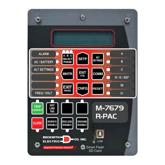
Page 79: Figure 2-1 M-7679 R-Pac Front Panel With Factory Default Pushbutton And Led Labels
DISABLE DISABLE DISABLE Smart Flash ® Integrated Protection Systems SD Card Figure 2-1 M-7679 R-PAC Front Panel with Factory Default Pushbutton and LED Labels LED 21 LED 22 LED 23 LED 1 LED 7 LED 2 LED 8 LED 3... -
Page 80: S1 - Select Phase Pushbutton (Leds 21, 22, 23)
M‑7679 R‑PAC Instruction Book S1 – SELECT PHASE Pushbutton (LEDs 21, 22, 23) Three-Phase Ganged Mode If the control operates in Three-Phase Ganged Mode "all three phases operate at the same time", then the SELECT PHASE pushbutton is not operable when performing TRIP or CLOSE command operations originating from the front panel pushbuttons. -
Page 81: S11 - Hot Line Tag (Led 14)
Front Panel Operation – 2 S11 – HOT LINE TAG (LED 14) The HOT LINE TAG pushbutton is a pre-programmed pushbutton that is permitted to be reprogrammed. When the HOT LINE TAG pushbutton is pressed, the Hot Line Tag feature will become active and inhibit all Close operations, regardless of the source of the Close command. -
Page 82: S16 - Reclose Disable (Led 19)
M‑7679 R‑PAC Instruction Book S16 – RECLOSE DISABLE (LED 19) The RECLOSE DISABLE pushbutton is a pre-programmed pushbutton that is permitted to be reprogrammed. When pressed, this pushbutton deactivates an enabled 79 Reclose function. LED 19 will illuminate amber indicating the enabled 79 Reclose function has been deactivated. Pressing this pushbutton when RECLOSE DISABLE is active will reinstate an enabled 79 Reclose function. -
Page 83: Ac/Battery (Led 2)
Front Panel Operation – 2 AC/BATTERY (LED 2) The AC element of the AC/BATTERY LED illuminates amber when 120 Vac power supply voltage is less than minimum level at the control terminals. The BATTERY element of the AC/BATTERY LED illuminates red when the battery is not healthy. Either the battery voltage is low;... -
Page 84: Hmi Menu Structure
M‑7679 R‑PAC Instruction Book HMI Menu Structure The HMI menu structure (Appendix A) consists of three levels; Header, Sub-Header and Data/Data Entry. From the header level the user can navigate to the adjacent headers with the or pushbuttons (Figure 2-3), go to the sub-header level by pressing ENT or ... -
Page 85: Figure 2-3 Hmi Menu Structure And Navigation Example
Front Panel Operation – 2 MAIN HEADERS UTILITIES MONITOR CONFIGURATION SETPOINTS COMMUNICATION UTIL SETP MNTR CNFG SETP COMM CNFG UTIL COMM MNTR To Access Sub-headers: USER LINES Nameplate LEA Config Nominal Voltage To Access Data/Data Entry Screens: 120.00 V l-g Nominal Current To Navigate through Menu Screens: 1.00 A... -
Page 86: User Lines
M‑7679 R‑PAC Instruction Book USER LINES The user station identification lines (User Lines) allow the user to uniquely identify the unit. The user can customize the User Lines for up to 8 individual device profiles. Each line of this display can have up to 20 ASCII characters (excluding "~"... -
Page 87: System Clock
Front Panel Operation – 2 SYSTEM CLOCK This feature allows the user to set the control internal clock. The clock is used to time stamp system events and oscillograph operations. The system clock also includes the ability to enable/disable Daylight Savings Time. -
Page 88: Monitor - Metering And Status
M‑7679 R‑PAC Instruction Book Monitor – Metering and Status Accessing the HMI Monitor Screens 1. Press MNTR. The menu will advance to MONITOR. 2. Press ENT or CNFG once. The unit will display Primary Metering. 3. Press MNTR or COMM as necessary to navigate to the desired MONITOR Sub-Header. 4. -
Page 89: Smart Flash Sd Card
Front Panel Operation – 2 Smart Flash SD Card Pressing the COMM Hot Button when a formatted Smart Flash SD Card (FAT32) is present in the SD Card slot, advances directly to the "Memory Card" menu. Depending on User Permissions, the Memory Card can now be utilized to: •... - Page 90 M‑7679 R‑PAC Instruction Book The unit will then display Check Config Match?. This allows the user to perform a configuration match check to verify the compatibility of the Setpoints file with the unit configuration. Select YES to perform an internal configuration match check.
-
Page 91: Saving Settings Files To A Smart Flash Sd Card
Front Panel Operation – 2 SAVING SETTINGS FILES TO A SMART FLASH SD CARD The Memory Card/Settings submenu is available to a user with the appropriate Access Permission. Settings and Clone files from the control may be saved to the SD Card. Saving Settings Files to a Smart Flash SD Card The Memory Card/Settings/Save Settings selection saves the control's (*.sup) file to the SD Card. -
Page 92: Saving Data Files To A Smart Flash Sd Card
M‑7679 R‑PAC Instruction Book SAVING DATA FILES TO A SMART FLASH SD CARD The Memory Card/Save Data Files submenu is available to a user with the appropriate Access Permission. The following data files are available to be saved onto an SD Card: •... -
Page 93: Overview
Overview Chapter 3 is designed for the person or group responsible for the System Setup, Configuration and Function Setpoints of the M-7679 R-PAC, and includes the following: • The System Setup Section provides the definitions of system quantities and equipment characteristics required by the control which include CT, VT configuration selection, and Input and Output assignments. -
Page 94: System Setup
M‑7679 R‑PAC Instruction Book System Setup System setup data is required for proper operation of the M-7679 R-PAC. The System Setup consists of defining common information like CT and VT ratios, nominal voltage rating, nominal current rating and defining the Active Profile, etc. Configuration information is common to all profiles, and should be entered before Setpoint settings. -
Page 95: Source Orientation Setting With Lea Hardware Options H6, L6 Or X6
System Application & Function Setpoints – 3 Figure 3-1 System Setup, Voltage Input H6, L6 or X6 (Independent Phase Capable) Source Orientation Setting with LEA Hardware Options H6, L6 or X6 This setting is used to determine on which side the calculation of demand metering and energy metering is done. -
Page 96: Ct Polarity Reversal Enable
M‑7679 R‑PAC Instruction Book CT Polarity Reversal Enable With LEA Hardware options H6, L6 or X6; enabling this setting reverses ONLY the current polarity by 180 degrees. 79 Global Operation Mode With Independent Phase Capable Options T and W, the "Use 79 Global Operation Mode" checkbox is available to allow the user to program a global setting for the 79 Operation Mode. -
Page 97: 69 Switch Operation
System Application & Function Setpoints – 3 Independent Phase Overcurrent Settings with 79 Global Operation Mode The "View Independent Phase Settings" checkbox is available in the Phase Overcurrent Setpoints screens (50P, 51P, 67P) in the following conditions: 1. The "Use 79 Global Operation Mode" is enabled 2. -
Page 98: Table 3-2 69 Switch Operation - Three Phase Ganged Recloser
M‑7679 R‑PAC Instruction Book Three Phase Ganged Recloser 69 Switch Operation= Three Phase External Lockout Handle Action: Lockout on all 3 Phases 69 Lockout Handle Phase A 69 Lockout on Phases A, B & C 69 Lockout Handle Phase B 69 Lockout on Phases A, B &... -
Page 99: Table 3-5 69 Switch Operation (Single Phase) - Global Operation Mode 3T3Lo
System Application & Function Setpoints – 3 Independent Phase Capable Recloser 69 Switch Operation= Single Phase 79 Global Operation Mode: TM (Trip Mode) and LOM (Lockout Mode) When 79 Recloser Relay is DISABLED, and TM = 3 Phase, LOM = 3 Phase External Lockout Handle Action Any 69 Lockout Handle ACTIVE... -
Page 100: Voltage Input Configuration
M‑7679 R‑PAC Instruction Book VOLTAGE INPUT CONFIGURATION The following Table lists the factory hardware options available for Voltage Inputs in the M-7679. Analog Hardware Voltage Input Options 120–300 Vac Voltage Inputs (4) LEA High Voltage Inputs (4) An0-An2 are confi gurable phase current, An3 is ground current, (3 LEAHs) An4-An6 are confi gurable load phase voltages and (1 LEAH) An7 is a source phase voltage or gnd voltage LEA Low Voltage Inputs (4) An0-An2 are confi gurable phase current, An3 is ground current, (3 LEALs) An4-An6 are... -
Page 101: Voltage Input Configuration Settings
System Application & Function Setpoints – 3 Voltage Input Configuration Settings When an LEA Hardware Option is present, the IPScom System Setup screen will contain an additional "Voltage Input Configuration" button. This selection will display the applicable Voltage Input Configuration screen. -
Page 102: Nominal Voltage Configuration - Lea Options H4, L4, X4, H6, L6 And X6
M‑7679 R‑PAC Instruction Book Nominal Voltage Configuration – LEA Options H4, L4, X4, H6, L6 and X6 The LEA Configuration settings are used by the DSP for LEAL and LEAH in order to calculate internal parameters such as multipliers for primary voltage calculation and scale factor to calculate a normalized voltage to 120 V. -
Page 103: Phase Angle Shift Compensation
System Application & Function Setpoints – 3 Calibrating at different voltage will always be with reference to 7200 Primary nominal voltage, the PTR will be recalculated and the RCF will always be 1. Calculation Formula for Secondary Voltage: NCF = (Nom V x PTR x RCF) / (Nom V Secondary Voltage = Lea Output Voltage * NCF Example 1:... -
Page 104: Ratio Correction Factor (Rcf) Auto Adjustment
M‑7679 R‑PAC Instruction Book RATIO CORRECTION FACTOR (RCF) AUTO ADJUSTMENT The Ratio Correction Factor Auto Adjustment feature allows IPScom to automatically calculate the correct RCF settings of the LEA sensors by selecting the "RCF Adjustment" button in the Voltage Input Configuration 3-5). -
Page 105: Dual Vt Configuration
System Application & Function Setpoints – 3 DUAL VT CONFIGURATION With LEA Voltage Input option H4, L4, X4, H6, L6 or X6, the M-7679 has the capability to allow two VT configuration settings, one for the Y side (VTy) and one for the Z side (VTz). The available settings are determined by the factory hardware configuration. -
Page 106: Open Delta - Vt Configuration
M‑7679 R‑PAC Instruction Book OPEN DELTA – VT CONFIGURATION The following diagrams illustrate several examples of Open Delta connections. Open Delta CA Example (LEA Hardware H6) Open-Delta CA Connection Example M-7679 Open-Delta Figure 3-9 Open Delta CA Connection Example Diagram Open Delta AB Example (LEA Hardware H6) Open-Delta AB Connection Example M-7679... -
Page 107: Open Delta Configuration Table
System Application & Function Setpoints – 3 Open Delta Configuration Table Terminal VT Configuration Assignment Open Delta AB Open Delta BC Open Delta CA Open Delta AB Open Delta BC Open Delta CA Open Delta AB Open Delta BC Open Delta CA Open Delta AB Open Delta BC Open Delta CA... -
Page 108: Interface Configurator
M‑7679 R‑PAC Instruction Book INTERFACE CONFIGURATOR Selecting Interface Configurator from the System Setup window, displays the Interface Configurator screen (Figure 3-12). Selecting a specific Recloser, Adapter Chassis, and Manufacturer from the dropdown list will automatically populate the initial settings for the Interface Type. This includes Inputs, Outputs, Pulse Width and Battery Type. -
Page 109: Coordination Of Terminal Phase Assignment With Digital Inputs/Outputs
System Application & Function Setpoints – 3 Coordination of Terminal Phase Assignment with Digital Inputs/Outputs This feature allows the Terminal Phase Assignment setting to associate the Analog Inputs with the Digital Inputs and Outputs of one pole to the Phase selected in the Terminal Phase Assignment setting, when using either the 32B Multi Recloser Interface or the 42B Multi Recloser Interface. -
Page 110: Figure 3-16 Custom Interface Type - Mismatch Allowed Warning Screen
M‑7679 R‑PAC Instruction Book 42B Multi Recloser Interface Type Terminal Phase Assignment Input 1 52a Phase A 52a Phase A 52a Phase B 52a Phase B 52a Phase C 52a Phase C Input 2 52b Phase A 52b Phase A 52b Phase B 52b Phase B 52b Phase C... -
Page 111: Interface Configurator - Connected Mode
System Application & Function Setpoints – 3 In addition, the CUSTOM Interface Type System Setup screen will display a message confirming that the Terminal Phase Assignment only controls the Analog Inputs. The Digital Inputs and Outputs can be configured manually to any phase operation and status respectively (Figure 3-17). -
Page 112: Interface Configurator - File Mode
M‑7679 R‑PAC Instruction Book If the user makes any manual changes to the pre-defined settings, the "Interface Type" will revert to CUSTOM, and the firmware does not make any changes. Selecting "Save" will write the manual settings to the control. This provides complete user customization. -
Page 113: Manually Setting The System Inputs
System Application & Function Setpoints – 3 MANUALLY SETTING THE SYSTEM INPUTS Figure 3-20 System Setup – Input Tab (with Extended I/O Three-Phase Ganged) Active State The Active State is used to invert the input states based on the connections. This allows the user to change the input state without physically changing the input on the back of the unit. -
Page 114: Figure 3-21 52B Phantom Digital Inputs
M‑7679 R‑PAC Instruction Book Phantom 52b Digital Input The digital input function "52b Phantom Phase X", where X can be either Phase A, B or C, provides the control with the capability to obtain the 52b contact status, even though the status contact is not available from the recloser. -
Page 115: Table 3-12 System Inputs - Three Phase Ganged
System Application & Function Setpoints – 3 Input Function Selection Refer to Table 3-12 Table 3-13 for the available Functions that may be assigned to each Input. NOTE: The Logic Table displayed in the Input screen will update based on the selected function. M-7679 System Inputs Function Selections with Interface Type CUSTOM Default Factory Settings Input... -
Page 116: Virtual Inputs
M‑7679 R‑PAC Instruction Book M-7679 System Inputs Function Selections with Interface Type CUSTOM Default Factory Settings Input Independent Phase Capable Input 1 52a Phase A (Default IN1) 52a Phase C 52a Phase B General Input 2 52b Phase A (Default IN2) 52b Phase B Gas Pressure 52b Phantom Phase B... -
Page 117: Profile Switching By Inputs
System Application & Function Setpoints – 3 Figure 3-22 System Setup – Virtual Input Tab PROFILE SWITCHING BY INPUTS Up to three inputs (IN 4 through IN 12) can be dedicated to switch among the 8 profiles of the M-7679. Table 3-14 shows the logic for the profile assignment. -
Page 118: Manually Setting The System Outputs
M‑7679 R‑PAC Instruction Book MANUALLY SETTING THE SYSTEM OUTPUTS Figure 3-23 System Setup – Output Tab (with Extended I/O Three-Phase Ganged) Output Characteristics Direct Mode – The contact can turn ON and OFF at any moment. Direct mode maintains the output contact energized as long as the condition that caused it to operate exists. -
Page 119: Table 3-15 System Outputs - Three Phase Ganged
System Application & Function Setpoints – 3 Close Phase A (B, C) – with Independent Phase Capable Recloser, designates contacts to be dedicated for the close command. There can be up to three close contacts: one for each phase operating independently or three close contacts operating simultaneously. -
Page 120: Independent Pole Operation
M‑7679 R‑PAC Instruction Book M-7679 System Outputs Function Selections with Interface Type CUSTOM Default Factory Settings Output Independent Phase Capable Output 1 Trip Phase A (Default OUT1) Trip Phase C Trip Phase B General Output 2 Close Phase A (Default OUT2) Close Phase C Close Phase B General... -
Page 121: Setting The User Lines
System Application & Function Setpoints – 3 SETTING THE USER LINES From the System Setup screen, select the User Lines tab (Figure 3-24). Enter the custom User Lines for up to 8 Profiles. This screen also allows the user to enter a custom SGI Definition for the SGI Sensitive Ground Indicator Function (Figure 3-25). -
Page 122: File Identifier
M‑7679 R‑PAC Instruction Book FILE IDENTIFIER The FIle Identifier tab displays the following Read Only information: • SUP File – Name and Date/Time when the file was loaded to the unit • DNP XML File – Name and Date/Time when the file was loaded to the unit •... -
Page 123: System Diagrams
System Application & Function Setpoints – 3 System Diagrams Source M-7679 R-PAC Protection, Automation and Control System for Recloser, Switch, Sectionalizer and Advanced Distribution Automation Applications N & I Y (3 V ) Frequency Frequency Overvoltage Negative Undervoltage Rate of •... -
Page 124: Figure 3-28 Three-Line Connection Diagram
M‑7679 R‑PAC Instruction Book M-7679 Typical Connection Diagram Source M-7679 Recloser Resistive Voltage Sensors 1 A / 5 A CT Configuration (Source) R Power (Feeder) F Load Figure 3-28 Three-Line Connection Diagram 3–32... -
Page 125: System Configuration From The Hmi
System Application & Function Setpoints – 3 System Configuration from the HMI SYSTEM CONFIGURATION The System Configuration settings detailed in this Chapter are also available in the Front Panel HMI. See Chapter 2 Front Panel Operation for an overview of the HMI Menu structure and navigation. 1. -
Page 126: Lea Y Side Settings
M‑7679 R‑PAC Instruction Book 5. Press ENT or CNFG once. The unit will display the following: LEA Hardware Continue through the LEA Common Set submenu to access the remaining LEA Common Settings. The displayed screens are based on the installed LEA hardware. The following is a representative list: •... -
Page 127: Lea Z Side Settings
System Application & Function Setpoints – 3 LEA Z Side Settings 1. Press CNFG to wake the unit. The menu will advance to CONFIGURATION. CONFIGURATION < > SETP COMM 2. Press ENT or CNFG once. The unit will display the following: Nameplate <... -
Page 128: Function Setpoints
M‑7679 R‑PAC Instruction Book Function Setpoints The individual protective functions, along with their pickup and timing settings are described in the following pages. Settings for disabled functions do not apply. Some menu and setting screens do not appear for functions that are disabled or not purchased. Setpoints screens are as they appear using S-7600 IPScom Communications Software. -
Page 129: Comparing Setpoint Files
System Application & Function Setpoints – 3 Comparing Setpoint Files Comparing Setpoint Files does not require IPScom to be connected to a control as long as the files to be compared are present on the PC. The File/Compare menu is available in the IPScom initial startup screen. Select File/Compare and select either ".sup Files"... -
Page 130: Configuring Functions
M‑7679 R‑PAC Instruction Book CONFIGURING FUNCTIONS Configuration of the control consists of enabling the functions for use in a particular application, designating the output contacts each function will operate, and which control/status inputs will block the function. The choices include four programmable output contacts (OUT 1–OUT 4) and four control/status inputs (IN 1–IN 4), or twelve programmable output contacts (OUT 1–OUT 12) and twelve control/status inputs (IN 1–IN 12) for units purchased with expanded I/O. -
Page 131: Setup/Setpoints
System Application & Function Setpoints – 3 Setup/Setpoints The Setup/Setpoints command displays the main Setpoints screen (Figure 3-30) from which the individual relay function screens are accessed. Selecting a Function button will display the corresponding function setpoints screen. Function Setpoints Screens Command Buttons Each Function Setpoints screen contains the following Command Buttons. -
Page 132: 25 Sync Check
M‑7679 R‑PAC Instruction Book 25 SYNC CHECK The sync check function (25) is used to ensure that the voltage magnitude, phase angle and frequency of the selected line reference phase (A, B or C) and the Bus (Vz selected to V ) are within acceptable limits sync before the control is synchronized. -
Page 133: Figure 3-32 Function 25 Sync Check Setpoints Screen
System Application & Function Setpoints – 3 Figure 3-32 Function 25 Sync Check Setpoints Screen Undervoltage Permission usage set to Sync (Line) < Bus Minimum Voltage Reference Phase (V ) set to Phase A, B or C (Bus) < Line Minimum Voltage sync Dead Line Dead Line –... -
Page 134: 27 Phase Undervoltage
M‑7679 R‑PAC Instruction Book 27 PHASE UNDERVOLTAGE Use the Phase Undervoltage function (27) to detect any condition causing long- or short-term undervoltage. Elements #5 3PH through #8 3PH, are total three-phase elements for permissive applications. The 3PH elements will not Pickup until all three phases have crossed the user defined threshold, and will not Timeout until all three phases have been picked up for the user defined time delay. -
Page 135: 27 Vz1 Undervoltage
System Application & Function Setpoints – 3 27 VZ1 UNDERVOLTAGE A single phase undervoltage element is available when the voltage input Vz1 is setup as 27/59. Use the 27 Vz1 Undervoltage function to detect any condition causing long term undervoltage on the line (load) side of the control. -
Page 136: 46Dt Negative-Sequence Definite Time Overcurrent
M‑7679 R‑PAC Instruction Book REVERSE UNDERPOWER REVERSE OVERPOWER TRIP TRIP TRIP TRIP Pick up Pick up Reverse --- Relay --- Forward Reverse --- Relay --- Forward • Negative Pickup • Negative Pickup • Overpower • Underpower FORWARD OVERPOWER FORWARD UNDERPOWER TRIP TRIP TRIP... -
Page 137: 46It Negative-Sequence Inverse Time Overcurrent
System Application & Function Setpoints – 3 46IT NEGATIVE-SEQUENCE INVERSE TIME OVERCURRENT The 46IT Inverse Time function can be selected as an IEC, IEEE, US, Traditional Recloser Curve (101-202), Definite Time or user defined Custom Curve. 46IT #2 through 46IT #5 screens are identical to 46IT #1. Figure 3-41 Function 46IT Negative-Sequence Inverse Time Overcurrent Setpoints Screen USER DEFINED CUSTOM CURVES The IPScom Setup/Custom Curve Editor selection allows the user to define up to four custom Inverse Time... -
Page 138: 46Bc Broken Conductor Detection
M‑7679 R‑PAC Instruction Book 46BC BROKEN CONDUCTOR DETECTION The 46BC Broken Conductor Detection function compares the ratio of the Negative Phase Sequence Current (I2) to the Positive Phase Sequence Current (I1), with a user-defined percentage threshold. I2/I1 is a relatively constant value for any load variation on three phases. However, when there is a broken conductor, this ratio increases very quickly. -
Page 139: 47 Negative-Sequence Overvoltage
System Application & Function Setpoints – 3 47 NEGATIVE-SEQUENCE OVERVOLTAGE The Negative-Sequence Overvoltage function provides protection for voltage unbalance and reverse phase sequence. The operating signal is V . Voltage unbalance can occur due to blown fuses on transformers, open conductors, load unbalance and other such events. Phase reversal may occur when lines are repaired and conductors are inadvertently swapped. -
Page 140: 50G Ground Instantaneous/Definite Time Overcurrent
M‑7679 R‑PAC Instruction Book 50G GROUND INSTANTANEOUS/DEFINITE TIME OVERCURRENT The 50G Ground Instantaneous/Definite Time Overcurrent function provides reliable protection for ground faults. This element can be set more sensitive than the phase overcurrent since ground current typically only exists during unbalanced conditions. The settings must be set such that they will not pickup for faults or conditions outside the immediate protective zone. -
Page 141: 50Gs Sensitive Ground Instantaneous/Definite Time Overcurrent
System Application & Function Setpoints – 3 Figure 3-48 Function 50N Residual Instantaneous/Definite Time Overcurrent Setpoints Screen 50GS SENSITIVE GROUND INSTANTANEOUS/DEFINITE TIME OVERCURRENT The 50GS Sensitive Ground Instantaneous/Definite Time Overcurrent function provides reliable protection for ground faults on high impedance grounded and ungrounded distribution systems. This element is set extremely sensitive since the ground fault current is very low. -
Page 142: 50Bf Breaker Failure
M‑7679 R‑PAC Instruction Book 50BF BREAKER FAILURE NOTE: The term breaker is used interchangeably with recloser. The control closes an output contact to trip the recloser when it detects a fault or other abnormal condition. Breaker failure protection provides another level of protection should the recloser fail to open. For example the control can send a direct transfer trip command to the first upstream switch that can break fault current should the recloser fail. -
Page 143: 51V Phase Inverse Time Overcurrent With Voltage Control Or Voltage Restraint
Disable Phase Overcurrent protection and enter the operating parameters. Use up to five individual elements to provide inverse time phase overcurrent protection. The M-7679 R-PAC provides over 50 different time- current curves plus four user programmable curves to facilitate coordination with other overcurrent elements in the network. -
Page 144: Figure 3-53 Inverse Time Overcurrent Characteristic
M‑7679 R‑PAC Instruction Book Curve Category Curve Selection IEC Curves (IEC 60255-151) Inverse, Very Inverse, Extremely Inverse IEEE Curves (IEEE C37.112) Moderately Inverse, Very Inverse, Extremely Inverse 101 (A); 102 (1); 103 (17); 104 (N); 105 (R); 106 (4); 107 (L); 111 (8*); Traditional Recloser Curves 112 (15);... -
Page 145: 51N Residual Inverse Time Overcurrent
System Application & Function Setpoints – 3 51N RESIDUAL INVERSE TIME OVERCURRENT The (51N) Residual Inverse Time Overcurrent function provides protection against ground faults and operates on the neutral current (I ). These elements have greater sensitivity than the phase overcurrent protection, but care should be taken to set the pickup above normal standing unbalance due to conditions such as unequal single phase load. -
Page 146: 51Gs Sensitive Ground Inverse Time Overcurrent
M‑7679 R‑PAC Instruction Book 51GS SENSITIVE GROUND INVERSE TIME OVERCURRENT The 51GS Sensitive Ground Inverse Time Overcurrent function provides protection against ground faults and operates on the single phase current input I . These elements are extremely sensitive to provide protection for high impedance grounded and ungrounded distribution systems. -
Page 147: 59Pp Phase-To-Phase Overvoltage
System Application & Function Setpoints – 3 59PP PHASE-TO-PHASE OVERVOLTAGE Use the Phase-to-Phase Overvoltage function (59PP) to detect overvoltage conditions. This element operates on Phase-to-Phase voltage (i.e., V ). Therefore it does not pickup due to ground effects such as ground potential rise or zero-sequence mutual coupling. Ranges and increments are presented in Figure 3-59. -
Page 148: 59Vz1 Overvoltage
M‑7679 R‑PAC Instruction Book Figure 3-61 Function 59I Peak Overvoltage Setpoints Screen (Shown: Three Phase Ganged) 59VZ1 OVERVOLTAGE A single phase overvoltage element is available when voltage input Vz1 is setup as 27/59. Use the 59Vz1 Overvoltage function to detect any condition causing long term overvoltage on the line side of the control. The function 59Vz1 can detect ground faults if the voltage input Vz1 is connected across a broken delta VT and provides protection for ground faults on the distribution feeder (Figure... -
Page 149: 67P Phase Directional Overcurrent
System Application & Function Setpoints – 3 67P PHASE DIRECTIONAL OVERCURRENT NOTE: 67P is intended to only operate for balanced three-phase faults. 67Q operates for phase- to-phase and phase-to-phase-to-ground while 67N (or 67G) operates for single phase-to- ground faults. Therefore, every fault type is covered (i.e., AG, BG, CG, AB, BC, CA, ABG, BCG, CAG and ABC). -
Page 150: Figure 3-65 67P Directional Characteristic With Angle Band Enabled
M‑7679 R‑PAC Instruction Book 90° Blocking Zone 180° 0° Trip Zone 270° = Polarizing Voltage (Reference) = Operate Current MSA = Maximum Sensitivity Angle Band = Angle Band Figure 3-65 67P Directional Characteristic with Angle Band Enabled Figure 3-66 Function 67P Directional Overcurrent Definite Time Setpoints Screen 3–58... -
Page 151: 67 Directionality View
System Application & Function Setpoints – 3 Figure 3-67 Function 67P Directional Overcurrent Inverse Time Setpoints Screen 67 Directionality View Selecting "Directionality View" in any 67 Function screen will display a graphical representation of the entered Maximum Sensitivity Angle. NOTE: MSA cannot be deselected, but the value may be changed. -
Page 152: 67N Residual Directional Overcurrent
M‑7679 R‑PAC Instruction Book Figure 3-69 Function 67 Directionality View Default MSA and Angle Band 67N RESIDUAL DIRECTIONAL OVERCURRENT Each Residual Directional Overcurrent element can be configured as Directional or Non-Directional. Forward or Reverse looking operation depends upon the setting for the Maximum Sensitivity Angle. The Figure 3-72 "Residual Directional Overcurrent –... -
Page 153: Figure 3-70 67N Residual Directional Overcurrent Definite Time Setpoints Screen
System Application & Function Setpoints – 3 Figure 3-70 67N Residual Directional Overcurrent Definite Time Setpoints Screen Figure 3-71 67N Residual Directional Overcurrent Inverse Time Setpoints Screen 3–61... -
Page 154: Figure 3-72 67N Residual Directional Overcurrent - Directional Characteristic
M‑7679 R‑PAC Instruction Book 90° Trip Zone Operate Polarizing Current I Voltage 180° 0° Block Zone 120° 270° Figure 3-72 67N Residual Directional Overcurrent – Directional Characteristic 90° Block Zone 180° 0° Polarizing Voltage Trip Zone Maximum Sensitivity Angle = +90° Operate Current 270°... -
Page 155: 67G Ground Directional Overcurrent
System Application & Function Setpoints – 3 67G GROUND DIRECTIONAL OVERCURRENT Each Ground Directional Overcurrent element can be configured as Directional or Non-Directional. Forward or Reverse looking operation depends upon the setting for the Maximum Sensitivity Angle. The Figure 3-74 "Ground Directional Overcurrent –... -
Page 156: Figure 3-75 67G Ground Directional Overcurrent - Polarizing Voltage And
M‑7679 R‑PAC Instruction Book 90° Block Zone 180° 0° Polarizing Voltage Trip Zone Maximum Sensitivity Angle = +90° Operate Current 270° Figure 3-75 67G Ground Directional Overcurrent – Polarizing Voltage and Operate Current (I for Forward Single Line-To-Ground Fault – Pure Reactive System = 3V Figure 3-76 67G Broken Delta Polarizing Source 3–64... -
Page 157: Figure 3-77 67G Ground Directional Overcurrent Definite Time Setpoints Screen
System Application & Function Setpoints – 3 Figure 3-77 67G Ground Directional Overcurrent Definite Time Setpoints Screen Figure 3-78 67G Ground Directional Overcurrent Inverse Time Setpoints Screen 3–65... -
Page 158: 67Q Negative-Sequence Directional Overcurrent
M‑7679 R‑PAC Instruction Book 67Q NEGATIVE-SEQUENCE DIRECTIONAL OVERCURRENT Each Negative-Sequence Directional Overcurrent element can be configured as Directional or Non-Directional. Forward or Reverse looking operation depends upon the setting for the Maximum Sensitivity Angle. The Figure 3-81 "Negative-Sequence Directional Overcurrent – Directional Characteristic" illustrates setting an element to be forward looking for unbalanced faults on a distribution feeder. -
Page 159: Figure 3-80 67Q Negative-Sequence Directional Overcurrent Inverse Time Setpoints Screen
System Application & Function Setpoints – 3 Figure 3-80 67Q Negative-Sequence Directional Overcurrent Inverse Time Setpoints Screen 90° Trip Zone Operate Polarizing Current Voltage 180° 0° 120° Block Zone 270° Figure 3-81 67Q Negative-Sequence Directional Overcurrent – Directional Characteristic 3–67... -
Page 160: 67Gs Sensitive Ground Directional Overcurrent
M‑7679 R‑PAC Instruction Book 90° Block Zone 180° 0° Polarizing Voltage Trip Zone Maximum Sensitivity Angle = +90° Operate Current 270° Figure 3-82 67Q Negative-Sequence Directional Overcurrent – Polarizing Voltage (V ) and Operate Current (I ) for Forward Unbalanced Fault – Pure Reactive System 67GS SENSITIVE GROUND DIRECTIONAL OVERCURRENT Each Sensitive Ground Directional Overcurrent element can be configured as Directional or Non-Directional. -
Page 161: Figure 3-83 67Gs Sensitive Ground Directional Overcurrent Definite Time Setpoints Screen
System Application & Function Setpoints – 3 Figure 3-83 67GS Sensitive Ground Directional Overcurrent Definite Time Setpoints Screen Figure 3-84 67GS Sensitive Ground Directional Overcurrent Inverse Time Setpoints Screen 3–69... -
Page 162: 81 Frequency
M‑7679 R‑PAC Instruction Book 81 FREQUENCY Frequency protection (81) provides overfrequency and underfrequency protection. This function has eight independent elements with their own pickup and time delay settings. The overfrequency mode is automatically selected when the frequency setpoint is programmed higher than the nominal frequency (50 or 60 Hz). The underfrequency mode is selected when the setpoint is programmed below the nominal frequency. -
Page 163: Figure 3-86 Function 81 Frequency Setpoints Screen
System Application & Function Setpoints – 3 Figure 3-86 Function 81 Frequency Setpoints Screen Over Frequency Trip Magnitude #1 61.0 60.8 60.6 60.4 Over Frequency Magnitude #2 60.2 Over Frequency Over Frequency Time Delay #1 Time Delay #1 Time (cycles) 60.0 Under Frequency Under Frequency... -
Page 164: 81R Rate-Of-Change Of Frequency
M‑7679 R‑PAC Instruction Book 81R RATE-OF-CHANGE OF FREQUENCY The Rate-of-Change of Frequency function (81R) can be used for load shedding or tripping applications. The function is automatically disabled during unbalanced system events such as faults and other disturbances when the function detects negative-sequence voltage (2.5 V or greater). The pickup and definite time delay settings should be based on simulation studies. -
Page 165: Cold Load Pickup Arming State
System Application & Function Setpoints – 3 Cold Load Pickup Arming State The CLP function armed state will install overcurrent override settings in preparation for a cold load condition (loss of load diversity). The arming state can be entered either automatically according to user programmed settings or remote/manual initiation. -
Page 166: Cold Load Pickup Restore To Normal State
M‑7679 R‑PAC Instruction Book CLP_Act_PU CLP_Act_PU “Active” LED ON CLP_InitiateTimer Enabled 1 = Cold Load Settings Override CLP_Initiate 0 = Normal Settings CLP_Initiated CLP_Override_Latch Breaker_Closed CLP_Auto_Act_PU CLP_Act_TO CLP_Arm_TO CLP_ActiveTimer CLP_Auto_Active_Latch CLP_Init_Act_PU CLP_Reset CLP_InitiateActiveTimer CLP_Initiate_Active_Latch CLP_Initiate_Latch Figure 3-90 Cold Load Pickup Activation Logic Diagram Cold Load Pickup Restore to Normal State NOTE: If no Restore to Normal checkbox is selected, the CLP override settings are not permitted... -
Page 167: Cold Load Pickup Setpoints
System Application & Function Setpoints – 3 CLP Below Minimum Trip This CLP Reset logic compares the measured current to a percentage setting of the lowest normal overcurrent trip setting. When the measured current falls below this setting, the below minimum trip timer will pickup. CLP resets to the normal overcurrent protection settings upon below minimum trip timer timeout. -
Page 168: Figure 3-94 Cold Load Pickup Setpoints - Inst./Def. Time Overcurrent (Three Phase Ganged)
M‑7679 R‑PAC Instruction Book Figure 3-94 Cold Load Pickup Setpoints – Inst./Def. Time Overcurrent (Three Phase Ganged) Figure 3-95 Cold Load Pickup Setpoints – Inverse Time Overcurrent (Three Phase Ganged) Cold Load Pickup Overcurrent Override Settings Tabs • If a normal overcurrent function element is not enabled, then the "Function Element to Override" selections are disabled (greyed out). -
Page 169: Figure 3-96 Cold Load Pickup Logic Diagram
System Application & Function Setpoints – 3 • The Phase A Override settings (50P and 51P) are used for ALL 3 Phases when: • The control is in Three Phase Ganged Mode • The Independent Phase Recloser Operation Mode is "3 Phase Trip-3 Phase Lockout" (3T3LO) •... -
Page 170: Hlt Hot Line Tag
M‑7679 R‑PAC Instruction Book HLT HOT LINE TAG Hot Line Tag settings are evaluated as protection elements. The Hot Line Tag elements include 50P, 51P, 50N, 51N, 50G/GS and 51G/GS. The HLT function will Trip AND Lockout. NOTE: The Default Definite Time for all 50 elements in HLT must be zero. The Hot Line Tag mode may be activated by the front panel pushbutton, an input contact, or a communication point. -
Page 171: Restore Auto Restoration
System Application & Function Setpoints – 3 RESTORE AUTO RESTORATION The Auto Restoration feature recloses the breaker after a loadshed caused by a non-overcurrent function (under/overvoltage or under frequency). Auto Restoration will ONLY occur when the trip is caused by the user selected F27 undervoltage, F59 overvoltage and/or F81 frequency functions. -
Page 172: Figure 3-98 Auto Restoration Setpoints Screen
M‑7679 R‑PAC Instruction Book Figure 3-98 Auto Restoration Setpoints Screen External Close Frequency Enable Schedule Time Enabled Reclose Voltage Enable Delay Enabled Abort Time TRIP (Load Shed) – – – – Figure 3-99 Auto Restoration Conceptual Logic Diagram 3–80... -
Page 173: Ipslogic
System Application & Function Setpoints – 3 IPSlogic The control provides eight logic functions and associated IPSlogic. These functions can be used in conjunction with IPSlogic to expand the capability of the unit by allowing the user to define customized operating logic. The IPSlogic Function can be programmed to perform any or all of the following tasks: •... -
Page 174: Programming Ipslogic
M‑7679 R‑PAC Instruction Book Programming IPSlogic CAUTION: Logic feedback is prohibited unless a LATCH gate has been used in the logic. Use ▲ of feedback without a LATCH gate can produce unpredictable results. 1. From the IPSlogic Setpoints screen, select IPSlogic. IPScom will activate the IPSlogic Editor Screen (Figure 3-101) which provides an interactive worksheet for programming the desired IPSlogic. -
Page 175: Chapter 3 System Application & Function Setpoints (Cont.)
System Application & Function Setpoints – 3 Add Logic Gates Use the "Gates" tool to drag and drop logic gates onto the worksheet. Hovering over a Gate will display a Tooltip with the Gate description. Figure 3-103 IPSlogic Editor "Gates" Tool Show Logical Analyzer (Oscilloscope) Use this tool to display the Oscilloscope for the currently selected IPSlogic circuit. -
Page 176: Lel Load Encroachment Logic
M‑7679 R‑PAC Instruction Book LEL LOAD ENCROACHMENT LOGIC Load encroachment logic (LEL) is a built in logic that when enabled, will supervise the 51P Time Overcurrent elements. Select Use LEL from the 51P Setpoints screen to enable LEL supervision as defined in the LEL Setpoints screen (Figure 3-106). -
Page 177: Load Encroachment Logic Graph
System Application & Function Setpoints – 3 Load Encroachment Logic Graph Select View LEL Graph from the Load Encroachment Logic Setpoints screen to display a graphical representation of the LEL settings (Figure 3-108). Figure 3-108 Load Encroachment Logic Graph LEL Directional Element F67 The LEL Directional Element setting selects which F67 Element is to be used to detect directionality. -
Page 178: Bm Breaker Monitor
M‑7679 R‑PAC Instruction Book Figure 3-110 LEL Directional Element F67P #1 Resultant Setpoints Screen BM BREAKER MONITOR The control records the amount of current carried in each phase each time the breaker trips. The control’s operational logic employs an algorithm integrating the amount of unfiltered AC current at the time of each trip and the number of operations (close to open) as a method of calculating wear. -
Page 179: Figure 3-112 Breaker Accumulator Status Screen - Timing Selection Method
System Application & Function Setpoints – 3 The breaker wear pickup thresholds may be set to either how much life is used in the breaker OR how much life remains in the breaker. These options are mutually exclusive. This selection is Common for all tabs. •... -
Page 180: Figure 3-114 Breaker Monitor Common Setpoints Tab
M‑7679 R‑PAC Instruction Book Figure 3-114 Breaker Monitor Common Setpoints Tab Figure 3-115 Breaker Monitor Element #1 Setpoints Tab Breaker Accumulator – Switching Life Curves Graph There are three Switching Life Curves, which are depicted in (Figure 3-116): • Meiden S-M72QCA •... -
Page 181: Ihr Inrush Harmonic Restraint
System Application & Function Setpoints – 3 Figure 3-116 Breaker Accumulator – Switching Life Curves Graph IHR INRUSH HARMONIC RESTRAINT Energizing a transformer creates a high transient current accompanied by a harmonic component. This high transient current is referred to as "inrush" current. The harmonics present during the inrush period allow the M-7679 to discern inrush transients from an actual fault condition, and apply appropriate restraint. -
Page 182: Figure 3-119 Inrush Harmonic Restraint Logic Diagram
M‑7679 R‑PAC Instruction Book SP = Setpoint Inrush Harmonics Detector > SP FUND Extract 2 and 4 & > 0.05pu of CT FUND secondary rating Ensures line Output, in %, is energized is from phase with Reset greatest % Dominant >... -
Page 183: 79 Recloser Relay
System Application & Function Setpoints – 3 79 Recloser Relay TRIP AND CLOSE LOGIC The breaker is tripped independently by any protective function. The 79 Automatic Reclose function is executed every quarter of a cycle after all the enabled protective functions have been executed at least once. The algorithm of the 79 Reclose function is state machine driven. -
Page 184: 79 Supervision Feature
M‑7679 R‑PAC Instruction Book 79 Supervision Feature The 79 Supervisory Functions allow the user to select those functions, or IPSlogic, that when tripped will cause the 79 reclosing operation to be blocked and eventually lockout if the selected supervision functions are still tripped after the supervision time has elapsed. -
Page 185: Breaker Status Truth Table
System Application & Function Setpoints – 3 Breaker Status Truth Table Breaker status 52A and 52B are used to determine whether the breaker circuit is open or closed. Input 1 is dedicated to monitor 52A and Input 2 is dedicated to 52B or common 52B/69 Lockout. Failure to do so will result in the relay displaying the wrong status and also some protective functions will not perform correctly. -
Page 186: Figure 3-123 Function 79 Lockout Algorithm Diagram (Three-Phase Ganged)
M‑7679 R‑PAC Instruction Book Overview of Lockout algorithm Is F79 Enabled Proceed with State If Manual or If Manual or Machine Driven Auto Remote Trip Remote Trip Reclose Algorithm State 12 No Lockout and Lockout and Send proceed to next Lockout and Send TRIP command to task... -
Page 187: Figure 3-124 Function 79 Lockout Algorithm Diagram (Independent Phase)
System Application & Function Setpoints – 3 Overview of Lockout algorithm (Independent Phase) Is F79 Enabled Proceed with State If Manual or Machine Driven Auto If Manual or Remote Trip Reclose Algorithm Remote Trip State 12 No Lockout Lockout and Send Lockout and Send and proceed to TRIP command to... -
Page 188: Phase Count And Ground Count Exceeded Lockout Algorithm
M‑7679 R‑PAC Instruction Book Reclose Count = 1 or greater Reclose Shot 1 State 2 Actual trip command sent State 4 ¼ cycle earlier Remaining Reclose Actual output firing 4 ms shots if exists (hardware delay) + max 1.3 ms Two Wire Interface delay State 3 State 5... -
Page 189: External Operation
System Application & Function Setpoints – 3 Reclose Shot Start Just Reset Timer OC Trip again at t Arm Just Reset Timer If t < t + T6 then LOCKOUT Manual immediately after Close TRIP LOCKOUT Reset at t ELSE If t ≥... -
Page 190: 79 Recloser Status Monitoring
M‑7679 R‑PAC Instruction Book 79 Recloser Status Monitoring Selecting Monitor/Recloser Status Monitoring from the IPScom main menu displays the Recloser Status Monitoring screen which allows real time monitoring of the recloser. See Figure 3-127 for an example of the status monitoring screen. NOTE: This example illustrates a situation where all four Reclose Sequences occurred, and the subsequent LOCKOUT condition. -
Page 191: 79 Recloser Relay Setpoints
System Application & Function Setpoints – 3 79 RECLOSER RELAY SETPOINTS The Recloser Relay screen allows the user to set the Reclosing Sequence and Reclose Interval. The Reclosing Sequence is an extension of the single Reclosing Operation. When a breaker opens and closes automatically, it will continue until the specified count is reached. -
Page 192: Resetting Targets
M‑7679 R‑PAC Instruction Book Resetting Targets All fault types detected are captured and displayed in a target. The last fault will remain latched in both the HMI display and IPScom Function Status screen until the fault is manually or automatically reset. Select the "Target"... -
Page 193: 79 Trip Reclose Sequence
System Application & Function Setpoints – 3 79 Trip Reclose Sequence The 79 Sequence tab (Figure 3-132) allows the user to select the protection functions that will increment the Auto-Reclose cycle for up to 5 Reclose Trips. IPSlogic may also be used to generate a trip. Figure 3-132 Function 79 Sequence –... -
Page 194: 27 Bus Side Voltage Supervision Setpoints
M‑7679 R‑PAC Instruction Book 27 Bus Side Voltage Supervision Setpoints Bus Side Voltage Supervision blocks reclosing until the bus voltage rises above the pickup setting. The Figure 3-136 illustrates the Bus Side Voltage Supervision operation. If the voltage does not come back before the supervision timer expires, then the reclosing logic automatically goes to lockout. -
Page 195: Figure 3-137 79 Recloser Relay Fast & Slow Curve Qualifiers Settings Screen
System Application & Function Setpoints – 3 Supported Communications Commands • Command Inactive – Disables all Fast and Slow curve commands. • Activate Both Phase and Ground Fast Curves (TPGF) – All selected 51P, 51G/GS/N and 46IT functions will switch to the fast curves designated by the BFCP and BFCG settings respectively. •... -
Page 196: Figure 3-139 Time Modifier Settings Screen
M‑7679 R‑PAC Instruction Book Fast/Slow Curve Time Modifier Selecting the Time Modifier checkbox and then clicking on the Time Modifier button, will display the Time Modifier settings screen (Figure 3-139). Figure 3-139 Time Modifier Settings Screen Time Modifier Settings Priority The Fast/Slow Curves Time Modifier settings enabled in the 79 Function, take precedence over the individual function Time Modifier settings. -
Page 197: Recloser Wizard
3-140) allows the user to verify the system settings of the M-7679 R-PAC. The user should carefully review the displayed settings to ensure that these settings match the hardware configuration. If these settings need to be edited, select the "Configuration"... -
Page 198: Recloser Wizard Profile Screen
M‑7679 R‑PAC Instruction Book Recloser Wizard Profile Screen The Recloser Wizard Profile screen (Figure 3-141) allows the user to edit the User Lines associated with each individual profile defined by the "Setting Profile to Create" entry. The User Lines can be used for a circuit description or a settings description. -
Page 199: Recloser Wizard Ground Overcurrent Settings Screen
System Application & Function Setpoints – 3 The "Trip Graph" and "Display all Graphs" selections display the selected curves individually or collectively, in a graphical logarithmic format as shown in Figure 3-143, Display All Graphs. CAUTION: When the user opens the Display All Graphs screen, IPScom will automatically ▲... -
Page 200: Figure 3-145 Ground Precedence Flowchart
M‑7679 R‑PAC Instruction Book Ground Precedence When Ground Precedence is selected, the following flowchart controls the lockout conditions. Count > Phase Count OLP = false OLP = true Count > GND Count OLG = false OLG = true OLP and OLG Lockout are true Ground... -
Page 201: Recloser Wizard Residual (Neutral) Overcurrent Settings Screen
System Application & Function Setpoints – 3 Recloser Wizard Residual (Neutral) Overcurrent Settings Screen The Recloser Wizard Residual (Neutral) Overcurrent Settings screen (Figure 3-146) is dedicated to the residual functions and its behavior is similar to the Phase Overcurrent Settings screen. Figure 3-146 Recloser Wizard Residual (Neutral) Overcurrent Settings Screen Recloser Wizard Hot Line Tag Settings Screen Figure 3-147 Recloser Wizard Hot Line Tag Settings Screen... -
Page 202: Recloser Wizard Automatic Reclosing Settings Screen
M‑7679 R‑PAC Instruction Book Recloser Wizard Automatic Reclosing Settings Screen The Automatic Reclosing settings screen (Figure 3-148) allows the user to modify the time delay between trip and automatic reclose of the breaker. Each type of fault has its own Reclose Interval. Sequence Coordination can also be configured for the number of desired trips. -
Page 203: Navigation Panel Screen
System Application & Function Setpoints – 3 Figure 3-150 79 Supervision Functions Screen Navigation Panel Screen The Navigation Panel screen (Figure 3-151) allows the user to perform the following: • Duplicate Function 79 settings • Configure Function 79 in other profiles •... -
Page 204: Independent Phase Operation Mode
M‑7679 R‑PAC Instruction Book Independent Phase Operation Mode The M-7679 R-PAC supports Independent Phase Capable Reclosers (when purchased), and includes four Independent Phase operation modes: • Three-Phase Trip and Three-Phase Lockout (3T3LO) • Single-Phase Trip and Three-Phase Lockout (1T3LO) • Single-Phase Trip and Single-Phase Lockout (1T1LO) •... -
Page 205: 1T3Lo - Single-Phase Trip And Three-Phase Lockout
System Application & Function Setpoints – 3 1T3LO – Single-Phase Trip and Three-Phase Lockout 1T1LO – Single-Phase Trip and Single-Phase Lockout 3T1LO – Three-Phase Trip and Single-Phase Lockout • Operation: – 1T3LO – A single phase trip will trip the corresponding assigned output to trip, and if one phase exceeds the maximum number of trips it was assigned, the control will lockout all three phases. -
Page 206: Ground (G)/Residual (N) Deactivate
M‑7679 R‑PAC Instruction Book It is important to note with Synchronized Phase Sequence, if Phase A is assigned 4 trips, Phase B = 3 trips and Phase C = 1 trip; and if Phase A timeout is faster than B and C, then Phase B and C will follow Phase A only until their trip count is reached. -
Page 207: Recloser Wizard Independent Phase Mode
M-7679 R-PAC Distribution Automation Package (Option V or W) The Distribution Automation Package adds the Switch/Sectionalizer Mode and the Loop Scheme Mode to the M-7679 R-PAC. These two modes are mutually exclusive. See Section 3.10 for detailed information regarding the Loop Scheme Mode. -
Page 208: Figure 3-153 Setpoints Screen With Switch/Sectionalizer Option
M‑7679 R‑PAC Instruction Book The M-7679 Recloser Control with Switch/Sectionalizer operation is available in two options: • Recloser with Switch/Sectionalizer Three Phase Ganged • Recloser with Switch/Sectionalizer Independent Phase Capable When the Switch/Sectionalizer option is purchased, the Setpoints screen will display an additional settings button (Figure 3-153). -
Page 209: Figure 3-155 Sectionalizer - Sequence Coordination Mode Example
System Application & Function Setpoints – 3 When SCM is enabled, the Line Sectionalizer application changes to a Line Recloser application for the last count of the Line Sectionalizer. At this instant, the fault current breaking capability of the Line Recloser is crucial;... -
Page 210: Figure 3-157 Sectionalizer Setpoints: Independent Phase Capable Operation Mode
M‑7679 R‑PAC Instruction Book Sectionalizer Independent Phase Capable Operation Mode In the Switch/Sectionalizer Independent Phase Capable mode there are three distinct operation modes available: • 3 Phase Sensing – 3 Phase Trip (3S-3T) • 1 Phase Sensing – 3 Phase Trip (1S-3T) •... -
Page 211: Figure 3-158 Sectionalizer Screen: Target Reset Timer Settings
System Application & Function Setpoints – 3 Resetting Sectionalizer Targets All fault types detected are captured and displayed in a target. The last fault will remain latched in both the HMI display and IPScom Function Status screen until the fault is manually or automatically reset. Select the "Target"... -
Page 212: Figure 3-160 Sectionalizer Fault Current Only Trigger Logic Diagram
M‑7679 R‑PAC Instruction Book Fault Current Only Logic Function Timeout Status Overcurrent Function Selection #2 State #3 State Start State Reset Timer If Switch Mode Enabled, Max Trip Count automatically defaults to 1, else, Max Trip Count is User Selectable from 1- 4 Trip Breaker End State >=... -
Page 213: Figure 3-162 Sectionalizer Current With Voltage Loss Trigger Logic Diagram
System Application & Function Setpoints – 3 Fault Current & Voltage Loss Logic Function Pickup Status Undervoltage Function Selection Function Timeout Status Overcurrent Function Selection #2 State #3 State Start State Reset Timer If Switch Mode Enabled, Max Trip Count automatically defaults to 1, Trip Breaker else, Max Trip Count is... -
Page 214: Figure 3-163 Inrush Current Restraint Diagram
M‑7679 R‑PAC Instruction Book The Inrush Current Restraint feature is activated by applying a Current Multiplier to the phase overcurrent trigger setpoints for a defined "Phase Duration" setting. The Phase Current Multiplier setting determines the control's response during this time duration. Fault triggering based on ground overcurrent is blocked during the "Ground Duration"... -
Page 215: Switch Mode
System Application & Function Setpoints – 3 Sectionalizer Monitoring The Sectionalizer Monitoring Screen (Figure 3-165) is available in the IPScom Monitor menu. The screen displays the Initiate Restraint status, Current Restraint status, Initiate Restraint Timer, and Current Restraint Timer for each phase. Figure 3-165 Sectionalizer Monitoring Screen Sectionalizer Reset The Sectionalizer is reset to its initial state (count = 0) when a CLOSE command is executed and the device... -
Page 216: 3.10 Loop Scheme Application
M‑7679 R‑PAC Instruction Book 3.10 Loop Scheme Application The primary function of the Loop Scheme is to enable automated reconfiguration of a distribution circuit upon loss of voltage on the source and/or load sides of a Switching Device. Such a scheme is dependent on having another circuit that can pick up as much of the dropped load as possible on the lost circuit, through a normally open Switching Device, commonly referred to as a Tie. -
Page 217: Figure 3-168 Loop Scheme With Three Reclosers
System Application & Function Setpoints – 3 Sectionalizing Recloser Source Side Load Side SOURCE 1 Source 1 Load Side Recloser Load Source 2 Sectionalizing Side Recloser Source Side Load Side SOURCE 2 Figure 3-168 Loop Scheme with Three Reclosers Midpoint Sectionalizing Recloser Recloser... -
Page 218: Figure 3-170 Loop Scheme With Midpoint Recloser Application
M‑7679 R‑PAC Instruction Book Sectionalizing Midpoint Sectionalizing Recloser Recloser Recloser Source Source Load Source Load Load Side Side Side Side Side Side SOURCE 1 Source 1 Load Side Load Load Recloser Load Load Source 2 Load Sectionalizing Midpoint Sectionalizing Side Recloser Recloser Recloser... -
Page 219: Loop Scheme Diagrams
System Application & Function Setpoints – 3 LOOP SCHEME DIAGRAMS Hot Line Tag On Loop Scheme Enable Start Sectionalizing & Midpoint Tie Recloser Mode Recloser Mode Wait for LS Ready Wait for LS Ready Wait for Dead Line & Voltage Restore Wait for Dead Line Wait for Reset Wait for Voltage Restore*... -
Page 220: Loop Scheme Voltage Control Logic
M‑7679 R‑PAC Instruction Book Loop Scheme Voltage Control Logic The Loop Scheme monitors when the voltage is lost and when the voltage is restored on both Y side and Z side independently. There are two Dead Line Sensing elements for Voltage Loss (Undervoltage), and two Live Line Sensing elements for Voltage Restore (Overvoltage). -
Page 221: Sectionalizing And Midpoint Recloser Dead Line Logic
System Application & Function Setpoints – 3 Sectionalizing and Midpoint Recloser Dead Line Logic Trip&Lockout Command Lockout State Voltage Loss Y Voltage Loss Z Dead Line Timeout Y Dead Line Timeout Z Breaker Closed Wait for LS Ready Wait for State #2 State Dead Line... -
Page 222: Sectionalizing Recloser Voltage Restore Confirm Logic
M‑7679 R‑PAC Instruction Book Sectionalizing Recloser Voltage Restore Confirm Logic Wait for Voltage Restore State Dead Line Sensing Pickup Y > Voltage Above Dead Line Y > > Dead Line Sensing Pickup Z > Voltage Above Dead Line Z > >... -
Page 223: Sectionalizing Recloser Live Line Logic
System Application & Function Setpoints – 3 Sectionalizing Recloser Live Line Logic Live Line Window Timeout Y Lockout State Live Line Window Timeout Z Wait for Wait for Voltage Restore State #4 State Reset After LS Action Voltage Restore Confirm Y Source Voltage is Z (Auto Reset) Start State... -
Page 224: Midpoint Recloser Live Line Logic
M‑7679 R‑PAC Instruction Book Midpoint Recloser Live Line Logic Live Line Window Timeout Y Lockout State Live Line Window Timeout Z State Wait for State #4 Reset Wait for Dead Line Voltage Restore Y After LS Action Voltage Restore Z Figure 3-177 Midpoint Recloser Live Line Logic Diagram Sectionalizing and Midpoint Recloser Reset Logic Auto Reset... -
Page 225: After Loop Scheme Logic
System Application & Function Setpoints – 3 After Loop Scheme Logic After LS Action After LS Action: Block Ground Function Ground Trip Block Ground Function Block Timer Block Reclosing Function After LS Action: Reclosing Block Reclosing Block Timer Midpoint Recloser Mode Profile Switch Command After LS Action: Profile Switch... -
Page 226: Tie Recloser Dead Line And Live Line Logic
M‑7679 R‑PAC Instruction Book Tie Recloser Dead Line and Live Line Logic Trip&Lockout Command Dead Line Timeout Y Lockout State Dead Line Timeout Z Breaker Trip Command Dual Voltage Loss: Auto Trip Voltage Loss Y Voltage Loss Z Dead Line Timeout Y Dead Line Timeout Z Breaker Opened Wait for... -
Page 227: Tie Recloser Reset Logic
System Application & Function Setpoints – 3 Tie Recloser Reset Logic Wait for Reset State Start State LS Reset On: IPSLogic IPSLogic Timeout LS Reset On: Manual Trip Breaker Opened Manually External Reset Breaker Trip Command LS After Reset: Auto Trip Profile Switch Command LS After Reset: Return To Profile... -
Page 228: Loop Scheme - Ipscom Settings
M‑7679 R‑PAC Instruction Book LOOP SCHEME – IPSCOM SETTINGS Source and Load Side Determination – All Loop Scheme Application Types The designation of which voltage input is the Source and which is the Load for all LS Application Types is determined by the Source Orientation setting in the IPScom Setup/Configuration/Relay/System Setup window (Figure 3-184). -
Page 229: Sectionalizing Recloser
System Application & Function Setpoints – 3 Loop Scheme Reset – All Loop Scheme Application Types The Loop Scheme is automatically RESET when voltage is restored from the Source side, as defined by the Source Orientation setting Vy or Vz. The control will then execute any "After Reset" actions that are selected. Sectionalizing Recloser The Sectionalizing Recloser is normally CLOSED. -
Page 230: Midpoint Recloser
M‑7679 R‑PAC Instruction Book Midpoint Recloser The Midpoint Recloser is normally CLOSED. The Midpoint Recloser applies to the grid topology illustrated in Figure 3-170, where the device labeled Midpoint Recloser is located. The Midpoint Recloser application, by default, operates on any phase voltage loss. However, the user is given the option to program the Midpoint Recloser to operate on 3 Phase Voltage Loss ONLY, by selecting the "3 Phase Dead Line Only"... -
Page 231: Tie Recloser
System Application & Function Setpoints – 3 Tie Recloser The Tie Recloser is normally OPEN. The Tie Recloser applies to the grid topology illustrated in Figure 3-171, where the device labeled Tie Recloser is located. The Tie Recloser application operates ONLY on 3 Phase Voltage Loss detection. -
Page 232: Loop Scheme Monitoring
M‑7679 R‑PAC Instruction Book Tie Recloser Half Loop Scheme Configuration To program the Tie Recloser in Half Loop Scheme (or one-way LS), at least one action must be selected for ONLY one source in the "LS Action on Dead Line" settings. This source selection indicates the desired circuit to restore if voltage is lost on that side. -
Page 233: 3.11 Common Setpoints
System Application & Function Setpoints – 3 3.11 Common Setpoints The following setpoints are NOT part of the individual profile. These are independent setpoints common to all profiles. These setpoints are located in the "Common Setpoints" tab of the Setpoints screen. PSBC IED POWER SUPPLY/BATTERY CHARGER MONITOR IED Power Supply Monitor The Power Supply Monitor alarms on delay when the input voltage to the Power Supply is too high or too... -
Page 234: M-2035 Analog Inputs Threshold Setpoints
M‑7679 R‑PAC Instruction Book M-2035 Analog Inputs Threshold Setpoints When any M-2035 Model is selected in the Battery Charger Model dropdown, a new setpoint selection is added to the Common Setpoints tab. The M-2035 Analog Inputs setpoints screen allows the user to set two voltage thresholds (0 to 30 Vdc) for each of the four analog inputs. -
Page 235: Close Circuit Monitor
System Application & Function Setpoints – 3 TCM Monitoring Input (Selectable) External Trip Relay Trip Output(s) Output Battery M-7679 Breaker Trip Coil Figure 3-193 Trip Circuit Monitoring Input Close Circuit Monitor Figure 3-192 displays the settings for the CCM function. The CCM inputs are provided for monitoring the continuity of the close circuits. -
Page 236: Figure 3-194 Recommended Close Circuit Monitoring Input Configuration
M‑7679 R‑PAC Instruction Book M-7679 Close Circuit Monitoring Input Station Battery Output Other Contact Contacts Legend Anti-pump relay prevents reclosing on a sustained close command. A spring charge limit switch shown with breaker closing spring discharged. Close Coil Latch check switch, closed when latch is reset. -
Page 237: 60Fl Vt Fuse Loss
System Application & Function Setpoints – 3 60FL VT FUSE LOSS Some functions may operate inadvertently when a VT fuse is blown or an event causes a loss of one, two, or all three potentials to the relay. Provisions are incorporated for both internal and external potential loss detection and blocking of user defined functions. -
Page 238: Figure 3-197 Fuse Loss (60Fl) Function Logic
M‑7679 R‑PAC Instruction Book Figure 3-197 Fuse Loss (60FL) Function Logic 3–146... -
Page 239: Thd/Tdd Total Harmonic Distortion/Total Demand Distortion
System Application & Function Setpoints – 3 THD/TDD TOTAL HARMONIC DISTORTION/TOTAL DEMAND DISTORTION The THD/TDD feature consists of two setpoints that can be used for alarm or tripping. Selecting THD or TDD will apply the selection to the entire element even when Individual Phase is enabled. For example, Element #1 can use TDD and Element #2 can operate on THD or both elements can use TDD or THD. -
Page 240: Figure 3-199 Thd/Tdd Setpoints Screen With Independent Phase Enabled (Partial)
M‑7679 R‑PAC Instruction Book Figure 3-199 THD/TDD Setpoints Screen with Independent Phase Enabled (Partial) 3–148... -
Page 241: Close Block Function
System Application & Function Setpoints – 3 CLOSE BLOCK FUNCTION When enabled, a Close Block condition will be in effect when the Voltage or Frequency is out of band. Each condition can be individually enabled or disabled. The voltage band is defined by an upper (F59) and lower limit (F27). -
Page 242: Figure 3-202 Recloser Status Monitoring Screen - Close Block Status And Override Command
M‑7679 R‑PAC Instruction Book Close Block Function Status The Recloser Status Monitoring screen indicates the Close Block status (Figure 3-202). This screen also allows the user to send a Close Block Override command. When a Close Block Override is active, the status is displayed in red. -
Page 243: Sgi - Sensitive Ground Indicator
System Application & Function Setpoints – 3 SGI – SENSITIVE GROUND INDICATOR NOTE: The SGI algorithm was designed to work reliably on an ungrounded (3 wire) system or a balanced system where the Phase CTs are capable of accurately producing 1 mA Secondary output current. -
Page 244: Voltage And Current Harmonics
M‑7679 R‑PAC Instruction Book Figure 3-205 SGI – Sensitive Ground Indicator Setpoints Screen Voltage and Current Harmonics Five voltage and five current harmonics are calculated in real time at a minimum rate of 4 times every cycle (every quarter cycle). The calculated harmonics are compared against a corresponding individual threshold. If any of the five voltage or five current harmonics exceeds its corresponding threshold for more than the Duration setting defined by the user, the SGI function will activate. -
Page 245: Sef Fundamental Signal
System Application & Function Setpoints – 3 Figure 3-207 Harmonic Targets Monitor Screen SEF Fundamental Signal The "SEF Fundamental Signal" section allows the user to save any selected 50GS elements to all profiles. Select "50GS Settings Group" in this window to display the 50GS function for the selected element (Figure 3-208). -
Page 246: Custom Supervision And Initiation Logic
M‑7679 R‑PAC Instruction Book Custom Supervision and Initiation Logic Two additional custom logic blocks use IPS Global Logic which can access the following signals: • Voltage and Current harmonics • Difference Ig Logic (Delta Ig) • Directionality Signal All other IPSlogic signals are also available for use in the custom SGI Supervisory and Initiation Logic blocks. IPS Global Logic The IPS Global Logic settings are available in the Common Setpoints tab. -
Page 247: Running On Battery During Ac Power Loss
System Application & Function Setpoints – 3 Running on Battery During AC Power Loss The unit will run on 24 Vdc battery when an AC power loss is detected, until the battery voltage drops below the "Minimum battery voltage to turn OFF IED (V Batt)"... -
Page 248: Optional Analog Output Module
M‑7679 R‑PAC Instruction Book OPTIONAL ANALOG OUTPUT MODULE The optional Analog Output Module is a current loop dual channel device capable of transmitting selected data as current from the M-7679 to third party utility grade devices using IPScom S-7600. The module contains two current loop outputs capable of providing two signal ranges, either 4-20 mA or 0-20 mA (configured individually per channel). -
Page 249: Enabling The Analog Output Module
System Application & Function Setpoints – 3 Enabling the Analog Output Module The module is installed in the rear communications Port 1 of the M-7679. To enable the Analog Output module, select "Analog Out" as the protocol in the IPScom Communication/Setup/Comm Port screen (Figure 3-214). -
Page 250: Figure 3-216 Measured Variable Parameter Selection List
M‑7679 R‑PAC Instruction Book Selecting the Measured Variable dropdown will display the full list of available parameters (Figure 3-216). Parameters available for Metering include: • Real, average, and reactive power (in Watts or VAr) for each phase • Magnitude of primary and apparent power in VA for each phase •... -
Page 251: 3.12 Configuring Setpoints From The Hmi
System Application & Function Setpoints – 3 3.12 Configuring Setpoints from the HMI SELECTING A PROFILE FOR EDITING 1. Press SETP to wake the unit. The menu will advance to "SETPOINTS". SETPOINTS < > MNTR CNFG 2. Press ENT or CNFG once. The unit will display the following: PROFILE <... -
Page 252: Example: Setting 50P, Element #1, Three-Phase Ganged Operation Mode
M‑7679 R‑PAC Instruction Book Example: Setting 50P, Element #1, Three-Phase Ganged Operation Mode The following steps outline the setup of Function 50P, Element #1, Three-Phase Ganged Operation mode. The steps to setup Elements #2 through #5, Functions 51P, 50G(GS), 51G(GS), 50N, 51N and High Current Lockout are similar. -
Page 253: Setting 79 Recloser Relay (Three-Phase Ganged)
System Application & Function Setpoints – 3 SETTING 79 RECLOSER RELAY (THREE-PHASE GANGED) 1. Press SETP to wake the unit. The menu will advance to "SETPOINTS". SETPOINTS < > MNTR CNFG 2. Press ENT or CNFG once. The unit will display the following: PROFILE <... -
Page 254: Setting 79 Recloser Relay Common Settings (Independent Phase Mode)
M‑7679 R‑PAC Instruction Book SETTING 79 RECLOSER RELAY COMMON SETTINGS (INDEPENDENT PHASE MODE) 1. Press SETP to wake the unit. The menu will advance to "SETPOINTS". SETPOINTS < > MNTR CNFG 2. Press ENT or CNFG once. The unit will display the following: PROFILE <... -
Page 255: Setting 79 Recloser Relay (Independent Phase Mode)
System Application & Function Setpoints – 3 12. Press ENT to activate Change Mode: Deactivate G/N DISABLE 13. Utilizing the arrow pushbuttons select ENABLE or DISABLE, then press ENT. The unit will display the selection. Deactivate G/N DISABLE or ENABLE 14. -
Page 256: Single Phase/Two Phase Operation Mode (Option P)
Phase Capable reclosers. Newer Independent Phase Capable reclosers provide the option to utilize one or two poles. The M-7679 R-PAC can be used to operate a recloser on an unbalanced system, and is fully configurable to match the desired operational needs. One pole operation provides protection and control features specific to a single phase application. -
Page 257: Figure 3-218 M-7679 Option P - One-Line Functional Diagram
System Application & Function Setpoints – 3 Source M-7679 R-PAC (Option P – DA Package Single Phase/Two Phase) Protection, Automation and Control System for Recloser, Switch, Sectionalizer and Advanced Distribution Automation Applications 27BSVS *See NOTE Frequency Frequency Overvoltage Phase Bus Side Rate of •... -
Page 258: System Setup (Option P)
M‑7679 R‑PAC Instruction Book SYSTEM SETUP (OPTION P) With Option P, the "Operation Type" is named "Unbalanced System Operation". The System Setup screen (Figure 3-219) features a new "79 Unbalanced Operation" Enable Terminal setting with three checkboxes. One terminal must be enabled for Voltage Input hardware options L4, H4 or X4. Any combination of two terminals may be enabled for Voltage Input hardware options L6, H6, or X6. -
Page 259: Pole And Phase Assignment Indicator
System Application & Function Setpoints – 3 Figure 3-221 Terminal Phase Assignment (Terminal 1 and 2 Selected) Pole and Phase Assignment Indicator A Pole and Phase Assignment Indicator field will display in the upper right corner of all settings, functions and feature screens where pole and phase assignment information is useful. -
Page 260: Figure 3-224 Voltage Input Configuration L6 (Two Pole Operation, Phase Assignment A-B)
M‑7679 R‑PAC Instruction Book Voltage Input Configuration The Voltage Input Configuration settings are identical to the standard M-7679 Voltage Input Configuration settings, but the screen will only display either one pole or two poles, based on the "Enable Terminal" setting. Figure 3-224 Voltage Input Configuration L6 (Two Pole Operation, Phase Assignment A-B) Inputs and Outputs The Inputs and Outputs functionality is the same as the standard Independent Phase Capable mode and... -
Page 261: Functions/Features Exclusive To Option P
System Application & Function Setpoints – 3 Figure 3-226 Single Pole Terminal 1, Phase Assignment A – Input Tab Figure 3-227 Single Pole Terminal 1, Phase Assignment A – Output Tab Manual Trip and Close The M-7679 Front Panel manual TRIP and CLOSE pushbutton functionality is the same as the standard Independent Phase Capable mode. -
Page 262: Load Current Present (Lcp)
M‑7679 R‑PAC Instruction Book Load Current Present (LCP) A "Load Current Present" function is available as a profileable setting in the "Settings Matrix" and "Setpoints" screen. This setting mimics a 50P element and is used to indicate the presence of load current. The settings include Pickup, Time Delay, Output and Blocking Input selections. -
Page 263: High Current Alarm
System Application & Function Setpoints – 3 P1_LOS Enabled P1_LCP Enabled Pole 1 Current P1_LCP Setting P1 Loss of Sensing P1_LOS_Pickup P1_LOS_Timeout P1_LOS Pickup Time Delay 0.05 * V Pole 1 Vy Voltage P1_LOS Latch Pole 1 Vz Voltage 0.1 * V P1_LOS_Reset P1_LOS Condition Reset Time Delay P2_LOS Enabled... -
Page 264: Recloser Relay (Option P)
M‑7679 R‑PAC Instruction Book Alarms – Loss of Sensing Detection and High Current Alarm The Loss of Sensing Detection Alarm and the High Current Alarm are enabled in the IPScom Setup/Alarms screen (Figure 3-233). Figure 3-233 IPScom Setup/Alarms Screen (Option P) 79 Recloser Relay (Option P) The 79 Recloser Relay setpoints screen has been redesigned for Option P (Figure... -
Page 265: Figure 3-235 79 Recloser Relay Setpoints (Option P - Two Pole Operation)
System Application & Function Setpoints – 3 Figure 3-235 79 Recloser Relay Setpoints (Option P – Two Pole Operation) 79 Recloser Relay – IPSlogic The 79 Recloser Relay setpoints screen includes an IPSlogic component which provides greater setting flexibility. When enabled, if associated IPSlogic is asserted, a trip/reclosing sequence will be triggered. The dropdown menu includes all Profilable and Common IPSlogic selections. -
Page 266: Settings Matrix
M‑7679 R‑PAC Instruction Book Settings Matrix The traditional I/O Map menu is replaced with the Settings Matrix and is modified for Option P. Features included in the Settings Matrix: • Enable/Disable Elements • Profile Selection • Select Outputs • Print/Print Preview •... -
Page 267: Setpoints (Option P)
System Application & Function Setpoints – 3 SETPOINTS (OPTION P) The available Function Setpoints for Option P have been modified or redesigned to accomodate One or Two Pole Operation. Minor modifications that maintain existing functionality are defined in Table 3-24. Those functions which have been significantly redesigned are detailed in the following pages. -
Page 268: Setpoints Modified For Option P
M‑7679 R‑PAC Instruction Book Setpoints Modified for Option P Standard Protection Functions Option P Function Option P Modifi cations 25 Sync Check Added Pole 1 and Pole 2 tabs, Reference Phase dropdown removed, Reference/Sync voltages are Vy1/Vz1 and Vy2/Vz2. 27 Phase Undervoltage Redesigned function: Four elements, each with Pole 1 and Pole 2 settings. -
Page 269: Setpoints Implementation (Option P)
System Application & Function Setpoints – 3 Setpoints Implementation (Option P) Setpoint screens update dynamically according to the Number of Poles and the Terminal Phase Assignments in the System Setup screen. Option P implementation allows for One or Two Pole Operation while maintaining standard functionality. -
Page 270: Figure 3-242 Function 27Vzs Undervoltage Setpoints (Option P - Two Pole Operation)
M‑7679 R‑PAC Instruction Book 27VzS Undervoltage and 59VzS Overvoltage The 27VzS and 59VzS functions are only available with Option P, and Voltage Input options L6, H6, or X6. With Single Pole Operation, the #1 element is associated with Pole 1 only (Vz1 analog input). With Two Pole Operation, the #2 element is associated with Pole 2 only (Vz2 analog input). -
Page 271: Figure 3-244 Cold Load Pickup Setpoints (Option P - Two Pole Operation)
System Application & Function Setpoints – 3 Cold Load Pickup (CLP) The Cold Load Pickup setpoints screen for Option P removes all Zero Sequence Overcurrent function overrides. In addition, new commands for manual activation of CLP are added to the Front Panel HMI and through communications. -
Page 272: Figure 3-246 Sectionalizer Setpoints (Option P - Two Pole Operation)
M‑7679 R‑PAC Instruction Book Sectionalizer The Sectionalizer function for Option P maintains existing functionality including built-in overcurrent and voltage elements. The "2PH Ganged Operation" setting is NOT available. With Two Pole Operation, Operation Mode dropdown selections are: "1 Phase Sensing-1 Phase Trip" and "1 Phase Sensing-2 Phase Trip". Figure 3-246 Sectionalizer Setpoints (Option P –... -
Page 273: Figure 3-248 Loop Scheme Sectionalizing Recloser Setpoints (Option P - Two Pole Operation)
System Application & Function Setpoints – 3 Loop Scheme The Loop Scheme function for Option P maintains existing functionality with the following modifications: • The "2PH Ganged Operation" setting is NOT available. • "3 Phase Dead Line Only" checkbox is removed. •... -
Page 274: Configuring Option P Setpoints From The Hmi
M‑7679 R‑PAC Instruction Book Figure 3-249 Loop Scheme Monitoring Screen (Option P – Two Pole Operation) CONFIGURING OPTION P SETPOINTS FROM THE HMI Setting Overcurrent Functions 1. Press SETP to wake the unit. The menu will advance to "SETPOINTS". SETPOINTS <... - Page 275 System Application & Function Setpoints – 3 7. Press CNFG as necessary, to access the 50 P1 settings screens: • 50 P1 (Enable/Disable) • Pickup 50 P1 (0.02 to 20.00 A) • Time Delay 50 P1 (0.01 to 600.00 seconds) 8.
-
Page 276: Setup Menu (Option P)
M‑7679 R‑PAC Instruction Book SETUP MENU (OPTION P) Setup/Configuration/Front Panel Functions Smart Button Functions Smart Button Functions are updated with Pole 1 and Pole 2 settings as shown in Figure 3-250. The following modifications are implemented in the Smart Buttons setup screen: Initiate •... -
Page 277: Figure 3-252 Datalog Csv Configuration (Option P)
System Application & Function Setpoints – 3 Setup/Data Logging/CSV Configuration Analog selections are updated to include Pole 1 and Pole 2. Functions that are not applicable for Option P are grayed out. Figure 3-252 Datalog CSV Configuration (Option P) Setup/Oscillograph and Setup/Sequence of Events New Oscillograph and Sequence of Events triggers for Option P functions and elements are added. -
Page 278: Monitor Menu (Option P)
M‑7679 R‑PAC Instruction Book Setup/Display All Settings This screen contains the settings for each control function within a single window to allow scrolling through all control setpoint and configuration values. Hyperlinks to allow the user to access the individual control function screen, review and/or change settings, then return to the scrolling Display All Settings screen. -
Page 279: Figure 3-255 Primary Metering Screen (Option P - Lea L6, H6, Or X6, Two Pole Operation)
System Application & Function Setpoints – 3 Monitor/Primary and Secondary Metering The Primary and Secondary Metering screens will dynamically update according to the Enable Terminal and Terminal Phase Assignment. Only the connected Pole measurements are displayed. Ground Current measurements and all Sequence Component measurements are removed. Figure 3-255 Primary Metering Screen (Option P –... -
Page 280: Figure 3-257 Counters Screen (Option P - Two Pole Operation)
M‑7679 R‑PAC Instruction Book Monitor/Counters The Counters screen will dynamically update according to the Enable Terminal and Terminal Phase Assignment. Only the enabled Poles and their associated Phases are displayed. Figure 3-257 Counters Screen (Option P – Two Pole Operation) Monitor/Function Monitoring/Recloser Status Monitoring The Recloser Status Monitoring screen will dynamically update according to the Enable Terminal and Terminal Phase Assignment. -
Page 281: Accessing Option P Monitor Screens From The Hmi
System Application & Function Setpoints – 3 ACCESSING OPTION P MONITOR SCREENS FROM THE HMI The Option P MONITOR screens will indicate P1 (Pole 1) and P2 (Pole 2, if enabled). Phases A, B, C, and 3 Phase values will not be displayed. 1. - Page 282 M‑7679 R‑PAC Instruction Book This Page Left Intentionally Blank 3–190...
-
Page 283: Overview
Microsoft. To maintain full Cyber Security compliance, it is recommended to upgrade to the latest Windows version. Hardware Required for Direct USB (Serial) Communication To use IPScom to communicate with a Beckwith Electric M-7679 R-PAC using a direct USB (serial) connection, a USB cable is required. 4–1... -
Page 284: Installing Ipscom
M‑7679 R‑PAC Instruction Book Installing IPScom The IPScom S-7600 installation program has been written to overwrite previous versions of IPScom. IPScom runs on Windows 7 or Windows 10 operating system. Familiarity with Windows is important in using IPScom. IPScom will be installed on the host PC's hard disk. While it does not require special installation procedures, an installation utility has been provided to make the process easier. -
Page 285: Direct Connection
TIA-232 connections. If over 50 feet of cable length is required, other technologies should be investigated. Other communication topologies are possible using the M-7679 R-PAC. An Application Note, "Serial Communication with Beckwith Electric's Integrated Protection System Relays" is available from the factory or from our website at www.beckwithelectric.com. -
Page 286: Initial Local Communications Using Direct Usb Connection
M‑7679 R‑PAC Instruction Book INITIAL LOCAL COMMUNICATIONS USING DIRECT USB CONNECTION When the control is connected to the PC utilizing a USB cable, Windows will enumerate the control as an HID device. NOTE: The M-7679 and IPScom S-7600 Communications Software are shipped from the factory with the same default communication parameters. -
Page 287: Serial Comm Port Setup
IPScom Remote Setup and Operation – 4 ® SERIAL COMM PORT SETUP NOTE: Communication must be established with the target control for this procedure, using the Direct USB Connection described previously. Select Communication/Setup/Comm Port. IPScom will display the Setup Comm Port screen (Figure 4-6). -
Page 288: Ethernet Port Setup From Ipscom
M‑7679 R‑PAC Instruction Book Dual Ethernet Support Optional Dual Ethernet hardware is supported which can provide two individual Mac addresses that act as separate connections, with two TCP stacks. Self-Healing Ring topology is supported using either a managed or unmanaged ethernet switch. Failover Network topology is also supported. ETHERNET PORT 2 PORT 3... -
Page 289: Overview Of Ipscom Features
• Alarm Status • Connection Status • IRIGB Status IPScom File Communication Utility Help File Utility Help M-7679 R-PAC Sequence of Events Viewer About M-7651A D-PAC Open PQ Viewer Import spf File Fault Recorder Event Viewer Recent Files BecoPlot Manage Access Permissions Compare .sup Files... -
Page 290: Figure 4-10 Ipscom Main Screen Menu Selections (1 Of 2)
M‑7679 R‑PAC Instruction Book IPScom S-7679 (M7679_6_1_M_H6_Ex_T_E0_0_file_031808) IPScom Header – File Mode: displays Smart String IPScom S-7679 - 10.10.3.199 (Modbus Ethernet Ch1) IPScom Header – Connected Mode: displays Connection Status File Communication Monitor Setup Utility Help File Setup Save File Select Active Profile Profile 1 Save File As... -
Page 291: Ipscom Quick Access Toolbar
IPScom Remote Setup and Operation – 4 ® File Communication Monitor Setup Utility Help Utility Help Remote Control Contents Remote Output Control About Update Firmware Hardware Auto-Calibration Information Calibration Cybersecurity Retrieve Calibration Data E-mail Support Set Date & Time Data Analysis Restore Calibration Data Date &... -
Page 292: Startup Screen/Utility/Banner Setup
M‑7679 R‑PAC Instruction Book Startup Screen/Utility/Banner Setup IPScom includes a Security Banner feature located in the Startup Screen Utility menu dropdown. The Security Banner feature, when enabled, will display a user defined message when connecting to a control. The Security Banner will be displayed when connecting to a control and requires the user to acknowledge the contents of the message before proceeding to connect/login. -
Page 293: Chapter 4 Ipscom Remote Setup And Operation (Cont.)
The File menu dropdown when IPScom is not connected to a control, or a file is not open provides the following features: New – Choose "M-7679 R-PAC" to open the New File Screen (Figure 4-14) which allows the user to enter... -
Page 294: Figure 4-14 New File Setup Screen
M‑7679 R‑PAC Instruction Book Figure 4-14 New File Setup Screen File Menu (File Mode or Connected Mode) File Save File Save File As Export spf File Export Setpoints to csv File Save Workspace Open Workspace Default Workspace Change Background Default E-mail Support Folder Close Read from Device Write to Device... - Page 295 IPScom Remote Setup and Operation – 4 ® The Default Workspace menu selection allows the user to select the IPScom default workspace at startup. The Default Workspace selections are: No Workspace, Last Workspace Loaded, and Default Workspace File. Change Background – This selection allows the user to select either a (*.jpeg) or (*.png) file to be used as the IPScom background image.
-
Page 296: Communication Menu
M‑7679 R‑PAC Instruction Book Communication Menu COMMUNICATION MENU (NOT CONNECTED) Communication The Communication (Not Connected) dropdown menu is displayed at the Com Port IPScom startup screen. This menu provides the user with access to the screens Modem that are necessary to establish communication with the target control. Menu TCP/IP selections include USB, Com Port, and TCP/IP. -
Page 297: Communication/Tcp/Ip
IPScom Remote Setup and Operation – 4 ® When communicating by way of a fiber optic loop network, echo cancelling is available by checking the Echo Cancel box. This command masks the sender’s returned echo. CAUTION: The Echo Cancel check box should only be used when several relays are connected ▲... -
Page 298: Communication Menu (Connected Or File Mode)
M‑7679 R‑PAC Instruction Book COMMUNICATION MENU (CONNECTED OR FILE MODE) Communication Disconnect Setup Comm Port The Communication dropdown menu is Ethernet Settings displayed when IPScom is connected to a control Protocol Address or in File Mode. This menu provides the user Comm Port Security with access to the screens that are necessary to Protocol... -
Page 299: Communication/Setup/Comm Port Security/Protocol Access
IPScom Remote Setup and Operation – 4 ® Communication/Setup/Comm Port Security/Protocol Access The Comm Port Security/Protocol Access submenu allows the user to enable/disable communication protocols to comply with cyber security requirements (Figure 4-19). Figure 4-19 Enable/Disable Protocol Access Screen Enable FTP The Enable FTP selection allows the user to download files using a dedicated FTP (read only) account. -
Page 300: Figure 4-20 Goose Simulation Enable Screen
M‑7679 R‑PAC Instruction Book IEC 61850/Goose Simulation This feature supports the data attribute "simulation", which is part of the Goose Control Block. This is implemented on the Goose Publisher side only. This selection allows the user to enable/disable the Simulation flag for the first Goose Control Block. -
Page 301: Communication/Setup/Protocol/Iec 60870
IPScom Remote Setup and Operation – 4 ® IEC 61850 Server Status When IPScom sends the IEC 61850 CID file, it can take about 15 seconds to store the file on the flash disk, and up to two minutes to parse the file. The state of the server changes in the following order, after the file upload is completed (assuming the IEC server is already running): 1. -
Page 302: Figure 4-23 M-7679 Dnp Configuration Screen
M‑7679 R‑PAC Instruction Book • File can be saved to disk. • Saved files can be sent to the connected control. • Items in the editor can be moved, added and removed by dragging and dropping. • Enable/Disable unsolicited response. •... -
Page 303: Setup/Communication Security/Radius Configuration
IPScom Remote Setup and Operation – 4 ® DNP Properties The DNP Properties screen (Figure 4-24) allows the user to set Source Address Validation parameters and also UDP Port Settings. Figure 4-24 DNP Properties Screen Setup/Communication Security/Radius Configuration For Cyber Security, IPScom allows the user to configure up to two Remote Authentication Radius servers. Figure 4-25 Radius Configuration Screen 4–21... -
Page 304: Setup/Communication Security/Ipsec Configuration
M‑7679 R‑PAC Instruction Book Setup/Communication Security/IPsec Configuration For Cyber Security, IPScom allows the user to enable Internet Protocol Security (IPsec). Select Enable from the IPsec Configuration dropdown menu. IPScom will display the "IPsec Enable Screen". IPsec Configuration/Configure Endpoint Selecting IPsec Configuration/Configure Endpoint displays the "Configure Endpoint" screen which allows the user to add and configure IPsec Endpoints. -
Page 305: Monitor Menu
IPScom Remote Setup and Operation – 4 ® Monitor Menu Monitor The Monitor Menu provides access to the screens used to monitor BECO vHMI the control parameters. The submenus provided are: BECO vHMI, Primary Metering Primary Metering, Secondary Metering, Phasor Diagram, Function Secondary Metering Status, Demand Metering, Harmonics, Sync Scope, Counters, Live Oscillograph, Breaker Accumulator Status, Harmonic Targets and... -
Page 306: Figure 4-29 Beco Vhmi Screen
M‑7679 R‑PAC Instruction Book BECO vHMI Screen Capture and Print • vHMI Screen Capture – generates a screen capture of the displayed vHMI and saves the capture as a *.JPG image in the folder where the Email Support Files are stored. •... -
Page 307: Monitor/Primary And Secondary Metering
IPScom Remote Setup and Operation – 4 ® Monitor/Primary and Secondary Metering Select Monitor/Primary (or Secondary) Metering from the IPScom Main Screen dropdown menu. IPScom will display the applicable Metering screen based on the Voltage Input option (Figure 4-30) which includes Metering data for Currents, Voltages, Sequence Components, Power and Frequency. -
Page 308: Monitor/Phasor Diagram
M‑7679 R‑PAC Instruction Book Monitor/Phasor Diagram The Phasor Diagram (Figure 4-31) provides the user with the ability to evaluate a reference Phase Angle to Phase Angle data from other windings. The data may be displayed in Primary or Secondary Metering values. -
Page 309: Monitor/Demand Metering
IPScom Remote Setup and Operation – 4 ® Monitor/Demand Metering The Demand Metering screen (Figure 4-33) displays real-time demand and metering information from an addressed control. All Demand History and Energy Metering Values include the date and time at which each occurred. -
Page 310: Figure 4-34 Demand Metering Power Targets And Corresponding Dnp Points
M‑7679 R‑PAC Instruction Book Demand Metering/Power Targets The Power Targets settings are used as thresholds for demand metering measurements. If the demand measurement exceeds the threshold value setting, the corresponding binary input status bit in the communication point will be set to TRUE. See the communication protocol documents for additional details. Figure 4-34 Demand Metering Power Targets and Corresponding DNP Points <... -
Page 311: Monitor/Harmonics
IPScom Remote Setup and Operation – 4 ® Monitor/Harmonics The input signal is sampled at 128 samples per cycle, giving an overall sampling rate of 7680 samples per second for a 60 Hz system. This provides the ability to reproduce signals of up to 3840 Hz. Therefore, up to the 63rd harmonic can be calculated using discrete Fourier transform with a fundamental frequency of 60 Hz. -
Page 312: Monitor/Sync Scope
M‑7679 R‑PAC Instruction Book Monitor/Sync Scope The Sync Scope monitoring screen (Figure 4-37) provides a graphic representation of the phase difference between the measured quantities, relating to Function 25 Sync Check. CAUTION: The M-7679 Sync Scope should not be used to determine phase conditions for manual ▲... -
Page 313: Table 4-1 Overcurrent Fault Detection Counters Logic
IPScom Remote Setup and Operation – 4 ® Fault Detection Modes Of Operation: Recloser Mode – In Recloser Mode, the M-7679 will monitor the timeouts of all the function elements selected in the Overcurrent Fault Detection setup screen, and increment the corresponding Phase, Neutral, or Ground counter (based on Table 4-1 logic) at the time an open command is issued. -
Page 314: Figure 4-38 Counters Screen
M‑7679 R‑PAC Instruction Book Recloser/Breaker Operation Alarm Limit The Operation Limit provides the user with the ability to set a predetermined alarm point for the number of Recloser/Breaker operations initiated by the control. When the Operation Limit setting is exceeded the Max Breaker Operations alarm will be triggered if enabled. -
Page 315: Monitor/Live Oscillograph
IPScom Remote Setup and Operation – 4 ® Monitor/Live Oscillograph Selecting the Live Oscillograph submenu item displays the Live Oscillograph confirmation screen. Select Yes and IPScom will display the Live Oscillograph screen 4-39). Select Start to display live data for (Figure the eight channels with Power, Power Quality, Phasors and Harmonics. -
Page 316: Monitor/M-2035 Analog Inputs (Optional)
M‑7679 R‑PAC Instruction Book Monitor/M-2035 Analog Inputs (Optional) When the M-2406 Cooper Form 6, M-2420 Inertia MSO, or M-2035 Module is purchased, the M-2035 Analog Inputs screen will display the thresholds settings and the measured voltage. When the measured voltage is below the threshold setting, the corresponding LED will illuminate RED. -
Page 317: Figure 4-43 Recloser Status Monitoring Screen (Three-Phase Ganged)
IPScom Remote Setup and Operation – 4 ® Monitor/Function Monitoring/Recloser Status Monitoring The Recloser Status Monitoring screen (Figure 4-43) displays the Breaker Status (Phase A, B, C), Reclose Status (Phase A, B, C), Fault Type, Reclose Settings, Fast/Slow Curve Selection, and the Close Block Status. -
Page 318: Status Monitoring Using The Web Browser Interface
M‑7679 R‑PAC Instruction Book Monitor/Function Monitoring/Loop Scheme Monitoring The Loop Scheme status may be observed in the Loop Scheme Monitoring window. The breaker status will display Trip (green) or Close (red) depending on the breaker status contacts. When the control enters Trip and Lockout Mode, the screen will display Trip LO (green). -
Page 319: Setup Menu
IPScom Remote Setup and Operation – 4 ® Setup Menu Setup Select Active Profile Configuration Recloser Wizard Setpoints Overcurrent Quick Editor Alarms Data Logging Oscillograph Sequence of Events The Setup menu provides access to the screens used to configure, monitor Overcurrent Fault Detection or interrogate the control. -
Page 320: Configuration/Front Panel Functions
M‑7679 R‑PAC Instruction Book Configuration/Front Panel Functions This selection displays the interactive Front Panel Setup screen (Figure 4-48). To customize the Front Panel, click on the Pushbutton or LED directly on the Front Panel image to access the configuration settings. Figure 4-48 Front Panel Setup Screen Reset Buttons State The default state of all front panel pushbuttons is OFF (e.g. -
Page 321: Programmable Pushbuttons Feature
IPScom Remote Setup and Operation – 4 ® Programmable Pushbuttons Feature The Programmable Button feature allows the user to customize the functionality of the front panel pushbuttons S10 through S17. The S10 (TRIP), S11 (HOT LINE TAG), S14 (CLOSE), S15 (REMOTE DISABLE), S16 (RECLOSE DISABLE) and S17 (GROUND DISABLE) pushbuttons are preprogrammed to default functions, but can be reprogrammed as needed. -
Page 322: Pushbutton Programming (Initiate Action/Block)
M‑7679 R‑PAC Instruction Book Pushbutton Programming (Initiate Action/Block) 1. Select Setup/Configuration/Front Panel Functions. IPScom will display the "Front Panel Setup" interactive screen. Hovering the cursor over a pushbutton will initiate a popup screen that displays the currently programmed function. Figure 4-49 Pushbutton Information Popup Screen 2. -
Page 323: Front Panel Setup/Remote Disable Pushbuttons
IPScom Remote Setup and Operation – 4 ® 2. Expand either Initiate or Blocks to display the available functions. Select the function to be added to the Smart Function pushbutton. The selected function will be displayed in one of the twenty Assigned Function slots. -
Page 324: Front Panel Setup/Leds
M‑7679 R‑PAC Instruction Book Example: Pushbutton S12 is assigned to Close Command, and pushbutton S14 is assigned to Remote Disable Initiate: • If the checkbox is CHECKED for pushbutton S12 (pushbutton S12 is participating in the Remote/ Local Disable Active Pushbutton feature): –... -
Page 325: Figure 4-52 Led Editor - Use Comment As Tooltip Example
IPScom Remote Setup and Operation – 4 ® Overview of LED Programming The LED programming feature consists of assembling various logical nodes that are linked to provide the logic to activate or deactivate the LEDs based on the status of the control functions. The LEDs can also be setup to accommodate inverse logic of the control functions. -
Page 326: Programming Leds
M‑7679 R‑PAC Instruction Book Programming LEDs 1. From the IPScom Main Menu, select Setup/Configuration/Front Panel Functions. IPScom will display the "Front Panel Setup" screen. 2. Click directly on the LED color (green, red or amber) to program that LED. IPScom will activate the LED Editor Screen that provides an interactive worksheet for programming the logic to activate or deactivate the LEDs based on the status of the control functions. -
Page 327: Table 4-2 Predefined Led Collective Function Input Definitions
IPScom Remote Setup and Operation – 4 ® There are predefined collective function LED inputs. See Table 4-2 for the collective function input definitions. Predefi ned LED Collective Function Input Defi nitions 27_1A_Pickup / 27_1B_Pickup / 27_1C_Pickup / 27_2A_Pickup / 27_2B_Pickup / ANY_F27_P 27_2C_Pickup / 27_3A_Pickup / 27_3B_Pickup / 27_3C_Pickup / 27_4A_Pickup / 27_4B_Pickup / 27_4C_Pickup... -
Page 328: Front Panel Setup/Wake Up Screen List
M‑7679 R‑PAC Instruction Book Front Panel Setup/Wake Up Screen List Click directly on the Wake Up pushbutton in the Front Panel Setup Screen to display the Wake Up Screen List (Figure 4-55). The Wake Up Screens feature allows the selection of specific parameters that will be displayed when the control is wakened by depressing the EXIT/Wake pushbutton. -
Page 329: Configuration/Fault Distance Parameters
IPScom Remote Setup and Operation – 4 ® Configuration/Fault Distance Parameters The Fault Distance Parameters window (Figure 4-56) allows the user to enter the necessary parameters used to calculate Fault distance. The fault distance is calculated without communications channels, special instrument transformers, or pre-fault information. -
Page 330: Fault Type Detection
M‑7679 R‑PAC Instruction Book Fault Type Detection Fault Type detection is performed when any current function (50P/N/G/GS, 46DT, 51P/N/G/GS, 46IT) times out. The M-7679 runs the Fault Type detection algorithm to determine the type of fault. The M-7679 calculates the fault type while also taking into consideration any previous fault. In the scenario of cascading faults, the latest fault type will be a combination of all of the previous faults. -
Page 331: Configuration/Harmonic Trigger
IPScom Remote Setup and Operation – 4 ® Configuration/Harmonic Trigger The Harmonic Trigger screen is available in the Configuration submenu and also in the IPScom/Common Settings SGI (Sensitive Ground Indicator) function screen. Harmonic Triggers are used in conjunction with the SGI feature as described in Chapter 3. Configuration/Fault Current 1stT Reset DNP Analog Input points have been added which will be captured in the First Trip (1stT) of a reclosing sequence and will remain frozen to avoid the potential inrush from the subsequent trips in a sequence. -
Page 332: Setup/Setpoints
M‑7679 R‑PAC Instruction Book SETUP/SETPOINTS The Setpoints menu selection displays the Setpoints screen from which the individual Function Setting screens can be accessed. A typical example of the Setpoints screen is represented by Figure 4-61. Depending on the Configuration, some functions might be grayed out. Selecting a Function Setting button will display the corresponding function screen. -
Page 333: Setup/Alarms
IPScom Remote Setup and Operation – 4 ® Figure 4-62 Overcurrent Quick Editor Screen SETUP/ALARMS The Alarms selection displays the Alarms screen (Figure 4-63). The following Alarms can be enabled or disabled: • Trip Close Alarm – occurs if the 52A and 52B contacts are in the same state. •... -
Page 334: Setup/Data Logging
M‑7679 R‑PAC Instruction Book Figure 4-63 Alarms Screen SETUP/DATA LOGGING The Extended Data Logging feature provides the user with the ability to initiate data logging of all control parameters for downloading at a later time. Data is recorded internally into non-volatile memory. Utilizing IPScom, the data log is transferred in both Comtrade (.cfg) and CSV formats. -
Page 335: Figure 4-65 Datalog Csv Configuration Screen
IPScom Remote Setup and Operation – 4 ® Each record captures the following data: • Active Profile • Current & Voltage (A, B, C, G, Vz1): Maximum/Inst./Average/Minimum Voltage shown on both Y and Z sides, based on LEA Input Configuration •... -
Page 336: Setup/Oscillograph
M‑7679 R‑PAC Instruction Book Data Logging/Clear When selected, the Clear command clears the data logging information stored in the control. NOTE: Whenever the M-7679 clock is reset and data logging is enabled the data log should be cleared. Data Log Saved to an SD Card When the data log is saved to an SD Card, the transferred data log consists of two files, an xml file (.xml) and the data file (.dat). -
Page 337: Figure 4-67 Oscillograph Trigger Selection Screen
IPScom Remote Setup and Operation – 4 ® Select Trigger Selection from the setup screen. To enable a trigger, scroll through the Trigger listing on the left side of the screen and drag the desired triggers to the "Enable Trigger" section on the right side of the screen. -
Page 338: Setup/Sequence Of Events
M‑7679 R‑PAC Instruction Book SETUP/SEQUENCE OF EVENTS Protective function Pickup, Trip, Dropout and/or Output/Input Pickup or Dropout are selected to trigger the Sequence of Events Recorder. The Setup command displays the Sequence of Events Trigger Setup screen (Figure 4-68). To enable a trigger, scroll through the Trigger listing on the left side of the screen and drag the desired triggers to the "Enable Trigger"... -
Page 339: Setup/Overcurrent Fault Detection
IPScom Remote Setup and Operation – 4 ® SETUP/OVERCURRENT FAULT DETECTION The Overcurrent Fault Detection feature allows the user to individually select the current protection elements that are allowed to participate in Fault Detection and Fault Counters (Figure 4-69). NOTE: Only the elements selected in the Overcurrent Fault Detection setup screen will increment the Pickup and Timeout counters (Monitor/Counters). -
Page 340: Setup/Display I/O Map
M‑7679 R‑PAC Instruction Book Figure 4-70 Overcurrent Fault Detection Triggers, Sectionalizer/Switch Mode SETUP/DISPLAY I/O MAP The Display I/O Map submenu displays the I/O Map screen (Figure 4-71), which contains a chart of programmed input and output contacts, and allows scrolling through all control output and blocking input configurations. -
Page 341: Setup/Custom Curve Editor
IPScom Remote Setup and Operation – 4 ® SETUP/CUSTOM CURVE EDITOR The Custom Curve Editor allows the user to define up to 4 custom Inverse Time Curves. See Chapter 3 for detailed information. SETUP/DISPLAY ALL SETTINGS Selecting Display All Settings displays the All Setpoints interactive screen (Figure 4-72). -
Page 342: Utility Menu
M‑7679 R‑PAC Instruction Book Utility Menu Utility Remote Control Remote Output Control Hardware Cybersecurity The Utility menu provides access to support features and functions, including Hardware Calibration, Cybersecurity Account Management, and access to Data Analysis powerful Data Analysis Tools. The submenus provided are: Remote Control, Remote Reboot* Remote Output Control, Hardware, Cybersecurity, Data Analysis, Remote View PPF Details... -
Page 343: Utility/Remote Output Control
IPScom Remote Setup and Operation – 4 ® UTILITY/REMOTE OUTPUT CONTROL CAUTION: Setting or Overriding Control Outputs remotely can adversely affect Recloser ▲ Operation. The following operations can be performed from the Remote Output Control screen Figure 4-74: • Energize or De-energize Output 1 or 2 •... -
Page 344: Hardware/Calibration
M‑7679 R‑PAC Instruction Book Hardware/Calibration Calibration/Auto-Calibration The Calibration/Auto-Calibration submenu item allows the user to perform a calibration of the control. Upon applying specified voltage and current inputs, the control will perform the calibration automatically and report the success or failure of the calibration. NOTE: Refer to Chapter 5, Auto Calibration for voltage and current input connections. -
Page 345: Hardware/Front Panel Labels
IPScom Remote Setup and Operation – 4 ® Hardware/Front Panel Labels Select Utility/Hardware/Front Panel Labels and choose either Vertical or Horizontal Model. IPScom will open the corresponding pdf form file in Adobe Acrobat (Figure 4-75). This form allows the user to create and print custom labels for the user programmable front panel LEDs and Pushbuttons. -
Page 346: Utility/Cybersecurity
M‑7679 R‑PAC Instruction Book UTILITY/CYBERSECURITY Cybersecurity/Manage Accounts The Manage Accounts feature allows the individual user to change their password at any time. The Security Policy Administrator is able to: • Send/Receive Account Permissions from the control • Manage the permissions associated with User Accounts and assign new Roles with customized permissions •... -
Page 347: Utility/Data Analysis
IPScom Remote Setup and Operation – 4 ® UTILITY/DATA ANALYSIS Data Analysis/SOE Viewer/Sequence of Events Viewer The Sequence of Events Viewer screen (Figure 4-77) allows the user to open and print Sequence of Events files. Double-click any event to display the "Sequence of Events Detailed Record" (Figure 4-78). -
Page 348: Data Analysis/Message Log
M‑7679 R‑PAC Instruction Book Data Analysis/SOE Viewer/PQ Viewer The PQ Events Viewer (Figure 4-79) allows the user to open and print ITIC data from a Sequence of Events file. Hovering over a plotted point will display the details of the event in the "Event Data" portion of the screen. Select the PQ Table Form tab to view the ITIC event parameters in a Table format. -
Page 349: Data Analysis/Trip Sequence Events
IPScom Remote Setup and Operation – 4 ® Data Analysis/Trip Sequence Events The M-7679 has the ability to record Recloser Trip Sequence Events and store the record in non-volatile memory. Any change in the Trip Sequence Event State will initiate recording. Each record contains the following data: •... -
Page 350: Data Analysis/Sd Card Download Converter
M‑7679 R‑PAC Instruction Book Data Analysis/SD Card Download Converter This feature allows Data Log or Oscillograph files downloaded from the M-7679 to an SD card to be converted to *.cfg file format. The Metering csv File selection prompts the user to open a Metering data file (*.csv) that has been downloaded to an SD card. -
Page 351: 4.10 Help Menu
IPScom Remote Setup and Operation – 4 ® 4.10 Help Menu Help Contents About The Help menu provides four selections. The Contents submenu will open a PDF file of the Instruction Book in the user's default PDF Reader. The Bookmarks Information pane allows direct access to selected topics. -
Page 352: Help/E-Mail Support
M‑7679 R‑PAC Instruction Book Help/E-mail Support When connected to a control, the E-mail Support feature allows the user to easily generate and send an E-mail request for technical support that contains all the pertinent data files associated with the technical support issue to support@beckwithelectric.com. -
Page 353: Figure 4-81 Becoplot Main Window With Submenus
IPScom Remote Setup and Operation – 4 ® BecoPlot – OSC 11-11-13.CFG File View Settings Window Help File View Settings Window Help Open... Device Information Select Wave Form Cascade About BecoPlot Close Select Color Arrange Icons Original Waveform Change Scale Print... -
Page 354: Markers
M‑7679 R‑PAC Instruction Book Figure 4-83 BecoPlot Window with Oscillograph Data Example Markers BecoPlot includes two user selectable markers. The first is positioned by double clicking on the plotted wave form data. The second is positioned by pressing and holding the SHIFT key and then double clicking on the plotted wave form data. -
Page 355: Right-Click Filter Menus
IPScom Remote Setup and Operation – 4 ® Right-Click Filter Menus Right-Click menus are available that allow filtering of the displayed data. By default, all available Datalog and Oscillograph file parameters are displayed. Right-Click on the top section of the Datalog or Oscillograph screen to filter the analog parameters to display. - Page 356 M‑7679 R‑PAC Instruction Book This Page Left Intentionally Blank 4–74...
- Page 357 Testing – 5 Testing Equipment/Test Setup ................5–2 Functional Test Procedures ..............5–4 Power On Self Tests ................5–6 25 Sync Check ..................5–7 27 Phase Undervoltage ................ 5–9 27PP Phase-to-Phase Undervoltage ..........5–10 27Vz1 Undervoltage ................5–11 32 Directional Power ................5–12 46DT Negative-Sequence Definite Time Overcurrent ......
-
Page 358: Equipment/Test Setup
Changes to some predefined configurations of the control may result in improper functionality. No calibration is necessary, as the M-7679 R-PAC is calibrated and fully tested at the factory. If calibration is necessary due to a component replacement, follow the auto calibration procedure detailed in Section 5.3... -
Page 359: Figure 5-2 Voltage Inputs: Configuration V2
Testing – 5 Balanced Voltage – + (ABC Phase Rotation) = |V | ∠ 0° Volts TEST = |V | ∠ -120° Volts TEST – + = |V | ∠ +120° Volts TEST = Varies Depending upon test – + –... -
Page 360: Functional Test Procedures
M‑7679 R‑PAC Instruction Book Functional Test Procedures This section details the test quantities, inputs and procedures for testing each function of the control. The purpose is to confirm the function’s designated output operation, the accuracy of the magnitude pickup settings, and the accuracy of time delay settings. Whereas the first test described, "Power On Self Test," does not require electrical quantity inputs, all other functional tests require inputs, and the necessary connection configurations are shown. -
Page 361: Figure 5-4 Typical External Connections
Testing – 5 IN 1 IN 2 IN 3 IN 4 OUT 1 OUT 2 OUT 3 OUT 4 ETHERNET TIA-232 PORT 2 PORT 3 PORT 1 PORT 4 WARNING! CONTACT WITH TERMINALS MAY CAUSE ELECTRIC SHOCK IN 5 IN 6 IN7 IRIG B llllllIIlllllIl SN:123456... -
Page 362: Power On Self Tests
M‑7679 R‑PAC Instruction Book POWER ON SELF TESTS VOLTAGE INPUTS: none CURRENT INPUTS: none 1. Apply proper power to the power input terminals. 2. The following sequence of actions will take place in the following order: a. Each time the control is powered up, it will briefly display a series of screens that include: •... -
Page 363: 25 Sync Check
Testing – 5 25 SYNC CHECK VOLTAGE INPUTS: Configuration V1 CURRENT INPUTS: None TEST SETTINGS: Undervoltage Permission Dead Line-Dead Bus Dead Line-Live Bus Live Line-Dead Bus (DLDB) (DLLB) (LLDB) Parameter Range Unit Accuracy Live Line Min. Voltage 0.0 to 200.0 V Volts ±... - Page 364 M‑7679 R‑PAC Instruction Book • Dead Line-Dead Bus is less than BM and V is less than LM. 1. Slowly decrease V and V magnitude until V sync sync The 25 SYNC CHECK green virtual LED will illuminate. 2. Increase V and V to the nominal voltage.
-
Page 365: 27 Phase Undervoltage
Testing – 5 27 PHASE UNDERVOLTAGE VOLTAGE INPUTS: Configuration V1 CURRENT INPUTS: None TEST SETTINGS: Parameter Range Unit Accuracy Pickup 10.00 to 300.00 V Volts ± 0.2 V or ± 0.5% Time Delay 0.00 to 600.00 s Seconds ± 0.01 s or ± 1% Programmed Outputs (1 to 12) –... -
Page 366: 27Pp Phase-To-Phase Undervoltage
M‑7679 R‑PAC Instruction Book 27PP PHASE-TO-PHASE UNDERVOLTAGE VOLTAGE INPUTS: Configuration V1 CURRENT INPUTS: None TEST SETTINGS: Parameter Range Unit Accuracy Pickup 10.00 to 300.00 V Volts ± 0.2 V or ± 0.5% Time Delay 0.00 to 600.00 s Seconds ± 0.01 s or ± 1% Programmed Outputs (1 to 12) –... -
Page 367: 27Vz1 Undervoltage
Testing – 5 27Vz1 UNDERVOLTAGE VOLTAGE INPUTS: Configuration V1 CURRENT INPUTS: None TEST SETTINGS: Parameter Range Unit Accuracy Pickup 10.00 to 300.00 V Volts ± 0.2 V or ± 0.5% Time Delay 0.00 to 600.00 s Seconds ± 0.01 s or ± 1% Programmed Outputs (1 to 12) –... -
Page 368: 32 Directional Power
M‑7679 R‑PAC Instruction Book 32 DIRECTIONAL POWER VOLTAGE INPUTS: Configuration V1 CURRENT INPUTS: Configuration C1 TEST SETTINGS: Parameter Range Unit Accuracy Pickup -3.00 to +3.00 PU Watts or VArs ± 0.02 PU or ± 6% Time Delay 0.00 to 600.00 s Seconds ±... - Page 369 Testing – 5 NEGATIVE REAL POWER: Pickup Test: 1. Verify the pickup setting is negative and the operating power is reactive. 2. Inject balanced nominal three-phase voltage. Pickup TEST 3. Calculate test current magnitude as follows: 3 • V 4. Apply balanced three-phase current 180 degrees out of phase with the voltage. 5.
-
Page 370: 46Dt Negative-Sequence Definite Time Overcurrent
M‑7679 R‑PAC Instruction Book 46DT NEGATIVE-SEQUENCE DEFINITE TIME OVERCURRENT VOLTAGE INPUTS: None CURRENT INPUTS: Configuration C1 TEST SETTINGS: Parameter Range Unit Accuracy Pickup 1 A CT 0.02 to 20.00 A Amps ± 0.1 A or ± 3% 5 A CT 0.10 to 100.00 A Amps ±... -
Page 371: 46It Negative-Sequence Inverse Time Overcurrent
Testing – 5 46IT NEGATIVE-SEQUENCE INVERSE TIME OVERCURRENT VOLTAGE INPUTS: None CURRENT INPUTS: Configuration C1 TEST SETTINGS: Parameter Range Unit Accuracy Pickup 1 A CT 0.02 to 3.20 A Amps ± 0.02 A or ± 3% 5 A CT 0.10 to 16.00 A Amps ±... - Page 372 M‑7679 R‑PAC Instruction Book Pickup Test: 1. Use IPScom Communications Software to monitor the 46IT function status. Slowly increase the Phase A Current Input until the 46IT NEGATIVE-SEQUENCE INVERSE TIME OVERCURRENT green virtual LED illuminates on the IPScom function status screen. The current level of operation will equal 3P amps ±...
-
Page 373: 46Bc Broken Conductor Detection
Testing – 5 46BC BROKEN CONDUCTOR DETECTION VOLTAGE INPUTS: None CURRENT INPUTS: Configuration C1 TEST SETTINGS: Parameter Range Unit Accuracy Pickup (I2/I1 ratio) 1 to 100 % ± 3% Time Delay 0.00 to 600.00 s Seconds ± 0.01 s or ± 1% Minimum I2 Level 0.02 to 20.00 A Amps... -
Page 374: 47 Negative-Sequence Overvoltage
M‑7679 R‑PAC Instruction Book 47 NEGATIVE-SEQUENCE OVERVOLTAGE VOLTAGE INPUTS: As described CURRENT INPUTS: None TEST SETTINGS: Parameter Range Unit Accuracy Pickup 0.00 to 300.00 V Volts ± 0.2 V or ± 0.5% Definite Time 0.00 to 600.00 s Seconds ± 0.01 s or ± 1% Programmed Outputs (1 to 12) –... -
Page 375: 50P Phase Instantaneous/Definite Time Overcurrent
Testing – 5 50P PHASE INSTANTANEOUS/DEFINITE TIME OVERCURRENT VOLTAGE INPUTS: None CURRENT INPUTS: Configuration C1 TEST SETTINGS: Parameter Range Unit Accuracy Pickup 1 A CT 0.02 to 20.00 A Amps ± 0.02 A or ± 3% 5 A CT 0.10 to 100.00 A Amps ±... -
Page 376: 50N Residual Instantaneous/Definite Time Overcurrent
M‑7679 R‑PAC Instruction Book 50N RESIDUAL INSTANTANEOUS/DEFINITE TIME OVERCURRENT VOLTAGE INPUTS: None CURRENT INPUTS: As described TEST SETTINGS: Parameter Range Unit Accuracy Pickup 1 A CT 0.02 to 20.00 A Amps ± 0.02 A or ± 3% 5 A CT 0.10 to 100.00 A Amps ±... -
Page 377: 50G Ground Instantaneous/Definite Time Overcurrent
Testing – 5 50G GROUND INSTANTANEOUS/DEFINITE TIME OVERCURRENT VOLTAGE INPUTS: None CURRENT INPUTS: As described TEST SETTINGS: Parameter Range Unit Accuracy Pickup 1 A Gnd CT 0.02 to 20.00 A Amps ± 0.02 A or ± 3% 5 A Gnd CT 0.10 to 100.00 A Amps ±... -
Page 378: 50Gs Sensitive Ground Instantaneous/Definite Time Overcurrent
M‑7679 R‑PAC Instruction Book 50GS SENSITIVE GROUND INSTANTANEOUS/DEFINITE TIME OVERCURRENT VOLTAGE INPUTS: None CURRENT INPUTS: As described TEST SETTINGS: Parameter Range Unit Accuracy Pickup 10 mA Gnd CT 0.001 to 0.160 A Amps (TBD) 50 mA Gnd CT 0.001 to 0.800 A Amps 0.0015 A or ±... -
Page 379: 50Bf Breaker Failure
Testing – 5 50BF BREAKER FAILURE VOLTAGE INPUTS: None CURRENT INPUTS: Configuration C1 TEST SETTINGS: Parameter Range Unit Accuracy Pickup Phase Current 1 A CT 0.02 to 2.00 A Amps ± 0.02 A or ± 3% 5 A CT 0.10 to 10.00 A Amps ±... -
Page 380: 51P Phase Inverse Time Overcurrent
M‑7679 R‑PAC Instruction Book 51P PHASE INVERSE TIME OVERCURRENT VOLTAGE INPUTS: None CURRENT INPUTS: Configuration C1 TEST SETTINGS: Parameter Range Unit Accuracy Pickup 1 A CT 0.02 to 3.20 A Amps ± 0.02 A or ± 3% 5 A CT 0.10 to 16.00 A Amps ±... - Page 381 Testing – 5 Time Test: 1. Connect a timer to output contacts (Z) so that the timer stops timing when the contacts (Z) close. 2. Apply current equal to the chosen test level calculated in Test Setup Step 5 to Phase A current input and start timing.
-
Page 382: Load Encroachment Logic (Lel)
M‑7679 R‑PAC Instruction Book 51P LOAD ENCROACHMENT LOGIC (LEL) NOTE: This procedure demonstrates how to test 51P when Load Encroachment Logic (LEL) is enabled. VOLTAGE INPUTS: Configuration V1 CURRENT INPUTS: Configuration C1 TEST SETTINGS: Forward Impedance 1 to 200 Ohms Reverse Impedance 1 to 200 Ohms Maximum Positive Angle Forward... -
Page 383: 51N Residual Inverse Time Overcurrent
Testing – 5 51N RESIDUAL INVERSE TIME OVERCURRENT VOLTAGE INPUTS: None CURRENT INPUTS: Configuration C1 TEST SETTINGS: Parameter Range Unit Accuracy Pickup 1 A CT 0.02 to 3.20 A Amps ± 0.02 A or ± 3% 5 A CT 0.10 to 16.00 A Amps ±... - Page 384 M‑7679 R‑PAC Instruction Book Time Test: 1. Connect a timer to output contacts (Z) so that the timer stops timing when the contacts (Z) close. 2. Apply current equal to the chosen test level calculated in Test Setup Step 5 to Phase A current input and start timing.
-
Page 385: 51G Ground Inverse Time Overcurrent
Testing – 5 51G GROUND INVERSE TIME OVERCURRENT VOLTAGE INPUTS: None CURRENT INPUTS: Configuration C1 TEST SETTINGS: Parameter Range Unit Accuracy Pickup 1 A CT 0.02 to 3.20 A Amps ± 0.02 A or ± 3% 5 A CT 0.10 to 16.00 A Amps ±... - Page 386 M‑7679 R‑PAC Instruction Book Time Test: 1. Connect a timer to output contacts (Z) so that the timer stops timing when the contacts (Z) close. 2. Apply current equal to the chosen test level calculated in Test Setup Step 5 to ground current input and start timing.
-
Page 387: 51Gs Sensitive Ground Inverse Time Overcurrent
Testing – 5 51GS SENSITIVE GROUND INVERSE TIME OVERCURRENT VOLTAGE INPUTS: None CURRENT INPUTS: Configuration C1 TEST SETTINGS: Parameter Range Unit Accuracy Pickup 10 mA Gnd CT 0.001 to 0.160 A Amps (TBD) 50 mA Gnd CT 0.001 to 0.800 A Amps 0.0015 A or ±... - Page 388 M‑7679 R‑PAC Instruction Book Time Test: 1. Connect a timer to output contacts (Z) so that the timer stops timing when the contacts (Z) close. 2. Apply current equal to the chosen test level calculated in Test Setup Step 5 to ground current input and start timing.
-
Page 389: 59P Phase Overvoltage
Testing – 5 59P PHASE OVERVOLTAGE VOLTAGE INPUTS: Configuration V1 CURRENT INPUTS: None TEST SETTINGS: Parameter Range Unit Accuracy Pickup 10.00 to 300.00 V Volts ± 0.2 V or ± 0.5% Time Delay 0.00 to 600.00 s Seconds ± 0.01 s or ± 1% Input Voltage Select –... -
Page 390: 59Pp Phase-To-Phase Overvoltage
M‑7679 R‑PAC Instruction Book 59PP PHASE-TO-PHASE OVERVOLTAGE VOLTAGE INPUTS: Configuration V1 CURRENT INPUTS: None TEST SETTINGS: Parameter Range Unit Accuracy Pickup (line-to-line) 10.00 to 300.00 V Volts ± 0.2 V or ± 0.5% Time Delay 0.00 to 600.00 s Seconds ±... -
Page 391: 59I Peak Overvoltage
Testing – 5 59I PEAK OVERVOLTAGE VOLTAGE INPUTS: Configuration V1 CURRENT INPUTS: None TEST SETTINGS: Parameter Range Unit Accuracy Pickup 100 to 150 % % of nominal voltage ± 3% Time Delay 0.01 to 140.00 s Seconds ± 0.05 s Programmed Outputs (1 to 12) –... -
Page 392: 59N Residual Overvoltage
M‑7679 R‑PAC Instruction Book 59N RESIDUAL OVERVOLTAGE VOLTAGE INPUTS: Configuration V1 CURRENT INPUTS: None TEST SETTINGS: Parameter Range Unit Accuracy Pickup 10.00 to 300.00 V Volts ± 0.2 V or ± 0.5% Time Delay 0.00 to 600.00 s Seconds ± 0.01 s or ± 1% Input Voltage Select –... -
Page 393: 59Vz1 Overvoltage
Testing – 5 59Vz1 OVERVOLTAGE VOLTAGE INPUTS: Configuration V1 CURRENT INPUTS: None TEST SETTINGS: Parameter Range Unit Accuracy Pickup 10.00 to 300.00 V Volts ± 0.2 V or ± 0.5% Time Delay 0.00 to 600.00 s Seconds ± 0.01 s or ± 1% Input Voltage Select –... -
Page 394: 60Fl Vt Fuse Loss Detection
M‑7679 R‑PAC Instruction Book 60FL VT FUSE LOSS DETECTION VOLTAGE INPUTS: Configuration V1 CURRENT INPUTS: Configuration C1 TEST SETTINGS: Parameter Range Unit Accuracy Time Delay 0.03 to 600.00 s Seconds ± 0.01 s or ± 1% Programmed Outputs (1 to 12) ±... -
Page 395: 67P Directional Phase Overcurrent
Testing – 5 67P DIRECTIONAL PHASE OVERCURRENT VOLTAGE INPUTS: Configuration V1 CURRENT INPUTS: Configuration C1 TEST SETTINGS: Parameter Range Unit Accuracy Direction (No-Direction, Directional) – – – – Polarization Voltage Max. Sensitivity Angle 0° to 359° Degrees – – – Angle Band + −... -
Page 396: Figure 5-7 Function 67 Directional Trip Characteristic (Forward Looking)
M‑7679 R‑PAC Instruction Book Block Zone 0° Test Trip Zone MSA = 270° (-90°) Figure 5-7 Function 67 Directional Trip Characteristic (Forward Looking) MSA = 90° Trip Zone 0° Block Zone Figure 5-8 Function 67 Directional Trip Characteristic (Reverse Looking) 5–40... -
Page 397: 67N Residual Directional Overcurrent
Testing – 5 67N RESIDUAL DIRECTIONAL OVERCURRENT VOLTAGE INPUTS: Configuration V1 CURRENT INPUTS: Configuration C1 TEST SETTINGS: Parameter Range Unit Accuracy – Direction (No-Direction, Directional) Operate Current – – – – – – Polarization Voltage Max. Sensitivity Angle 0° to 359° Degrees –... -
Page 398: 67G Ground Directional Overcurrent
M‑7679 R‑PAC Instruction Book 67G GROUND DIRECTIONAL OVERCURRENT VOLTAGE INPUTS: Configuration V1 CURRENT INPUTS: Configuration C1 TEST SETTINGS: Parameter Range Unit Accuracy – Direction (No-Direction, Directional) Operate Current – – – – – – Polarization Voltage Max. Sensitivity Angle 0° to 359° Degrees –... -
Page 399: 67Q Negative-Sequence Directional Overcurrent
Testing – 5 67Q NEGATIVE-SEQUENCE DIRECTIONAL OVERCURRENT VOLTAGE INPUTS: Configuration V1 CURRENT INPUTS: Configuration C1 TEST SETTINGS: Parameter Range Unit Accuracy – Direction (No-Direction, Directional) Operate Current – – – – – – Polarization Voltage Max. Sensitivity Angle 0° to 359° Degrees –... -
Page 400: 67Gs Sensitive Ground Directional Overcurrent
M‑7679 R‑PAC Instruction Book 67GS SENSITIVE GROUND DIRECTIONAL OVERCURRENT VOLTAGE INPUTS: Configuration V1 CURRENT INPUTS: Configuration C1 TEST SETTINGS: Parameter Range Unit Accuracy Direction (No-Direction, Directional) Operate Current – – – – – – Polarization Voltage Max. Sensitivity Angle 0° to 359° Degrees ±... -
Page 401: Recloser (Trip Recloser Sequence, 50Hcl And 27Bsvs)
Testing – 5 79 RECLOSER (TRIP RECLOSER SEQUENCE, 50HCL AND 27BSVS) VOLTAGE INPUTS: Configuration V1 CURRENT INPUTS: Configuration C1 TEST SETTINGS: Trip Reclose Sequence (per trip) Function 50G(GS) ... - Page 402 M‑7679 R‑PAC Instruction Book Parameter Range Unit Accuracy Bus Side Voltage Supervision VMINCL Min. Closing Voltage 0.00 to 300.00 V Volts ± 0.2 V or ± 0.5% TVMINCL Supervision Time 0.00 to 600.00 s Seconds ± 0.01 s or ± 1% Programmed Outputs Phase Fault Trip: TRIP_PH...
-
Page 403: Figure 5-9 Recloser Status Monitoring Screen
Testing – 5 Figure 5-9 Recloser Status Monitoring Screen Real Time Function Status Monitoring: 1. Use S-7600 IPScom Communications Software to monitor the Function Status. 2. Select Monitor/Function Status from the IPScom Main screen menu bar. IPScom will display the Function Status screen (Figure 5-10) which displays the status of the following: •... -
Page 404: Figure 5-11 Two Shot Reclose Auto-Reclose Cycle
M‑7679 R‑PAC Instruction Book Reclose Delay Time Tests: Figure 5-11 illustrates a two shot auto-reclose cycle that goes to lockout following the third trip. Observe the reclose delay time following each trip by monitoring the close output. NOTE: Reclose delays for phase and ground each trip can be set independently. NOTE: 51R represents 51G and/or 51N. -
Page 405: Figure 5-13 Sequence Coordination Example
Testing – 5 Sequence Coordination Test: illustrates how sequence coordination works: Figure 5-13 Substation time Slow Curves Fast Curves Multiples of Pickup 1.5 x Figure 5-13 Sequence Coordination Example Example: Recloser R is located at the substation while recloser R is a recloser located further downstream in the distribution system. - Page 406 M‑7679 R‑PAC Instruction Book High Current Phase Lockout Time Test: 1. Connect a timer to the trip output contact so that the timer stops timing when the contacts close. 2. Repeat steps 1 and 2 from the High Current Phase Lockout Pickup Test. 3.
-
Page 407: 81 Frequency
Testing – 5 81 FREQUENCY VOLTAGE INPUTS: Configuration V1 CURRENT INPUTS: None TEST SETTINGS: Parameter Range Unit Accuracy Pickup 40.00 to 65.00 Hz ± 0.02 Hz Time Delay 0.00 to 600.00 s Seconds ± 0.01 s or ± 1% Hysteresis 0.0 to 1.0 Hz –... -
Page 408: 81R Rate Of Change Of Frequency
M‑7679 R‑PAC Instruction Book 81R RATE OF CHANGE OF FREQUENCY VOLTAGE INPUTS: Configuration V1 CURRENT INPUTS: None TEST SETTINGS: Parameter Range Unit Accuracy Pickup 0.20 to 5.00 Hz/s Hz/Sec ± 0.02 Hz/s Time Delay 0.00 to 2.00 s Seconds ± 0.01 s or ± 1% Programmed Outputs (1 to 12) –... -
Page 409: Figure 5-15 Function 81R Connection Diagram
Testing – 5 (F81 #1) (F81 #2) Blocking Input Figure 5-15 Function 81R Connection Diagram Pickup Test: 1. Apply nominal voltage to all three phases. Calculate the time for the pickup setting and apply a sweep rate 25% less than the pickup (P). 2. -
Page 410: Clp Cold Load Pickup
M‑7679 R‑PAC Instruction Book CLP COLD LOAD PICKUP VOLTAGE INPUTS: Configuration V1 CURRENT INPUTS: Configuration C1 TEST SETTINGS: Parameter Range Unit Time Locked Out to Activate Cold Load Seconds (1 to 60000) Number of Recloses – (0 to 4) Restore to Normal: Active Duration Seconds (1 to 10000) - Page 411 Testing – 5 Parameter Range Unit 51N1 or 51G1 (Minimum Ground Trip): Pickup Amps (0.02 to 3.20) – – Curve: IEC – Inverse, Very Inverse, Extremely Inverse US – Moderately Inverse, Standard Inverse, Very Inverse, Extremely Inverse, Short Time Inverse IEEE –...
-
Page 412: Figure 5-16 Restore To Normal Logic Diagram
M‑7679 R‑PAC Instruction Book Time to Activate Cold Load Pickup Test: 1. Place the recloser in the lockout state. 2. Use the IPScom Recloser Status Monitoring screen to monitor the Cold Load Pickup virtual LED. NOTE: The breaker must be closed. 3. - Page 413 Testing – 5 Active Duration Time Test: 1. Place the recloser in the lockout state with no current applied to the recloser. 2. Use the IPScom Recloser Status Monitoring screen to monitor the Cold Load Pickup virtual LED. The recloser must be in the Cold Load Pickup state before proceeding to the next step. NOTE: The breaker must be closed.
-
Page 414: Hlt Hot Line Tag
M‑7679 R‑PAC Instruction Book HLT HOT LINE TAG NOTE: Hot Line Tag functions are treated as individual protection elements (HLT50P, HLT51P, HLT50G/GS, HLT51G/GS) causing a TRIP ONLY (OUT1, OUT5 and OUT7) and Drive to LOCKOUT. HLT functions are armed when HLT is activated AND HLT individual function settings are enabled. -
Page 415: Tcm Trip Circuit Monitoring
Testing – 5 TCM TRIP CIRCUIT MONITORING VOLTAGE INPUTS: As Described CURRENT INPUTS: None TEST SETTINGS: Parameter Range Unit Accuracy Time Delay 0.01 to 600.00 s Seconds ± 0.01 s or ± 1% Programmed Outputs (1 to 12) – Test Setup: 1. -
Page 416: Ccm Close Circuit Monitoring
M‑7679 R‑PAC Instruction Book CCM CLOSE CIRCUIT MONITORING VOLTAGE INPUTS: As Described CURRENT INPUTS: None TEST SETTINGS: Parameter Range Unit Accuracy Time Delay 0.01 to 600.00 s Seconds ± 0.01 s or ± 1% Programmed Outputs (1 to 12) – Test Setup: 1. -
Page 417: Bm Breaker Monitor And Accumulator
Testing – 5 BM BREAKER MONITOR AND ACCUMULATOR VOLTAGE INPUTS: None CURRENT INPUTS: As Described TEST SETTINGS: Parameter Range Unit Pickup (1 to 100) Delay (0.00 to 600.00) Seconds – T, IT or I – Timing Method Preset Accumulators: Phase A, B, or C –... -
Page 418: Psm Ied Power Supply Monitoring
M‑7679 R‑PAC Instruction Book PSM IED POWER SUPPLY MONITORING VOLTAGE INPUTS: + and – Terminals on the Power Supply inputs CURRENT INPUTS: None TEST SETTINGS: Power Supply Type Low Voltage High Voltage (24/48 Vdc) (125/220 Vac/Vdc) Parameter Unit Accuracy Time Delay Seconds (0 to 60000) Reference High Voltage... -
Page 419: Auto Calibration
Testing – 5 Auto Calibration VT CALIBRATION PROCEDURE The M-7679 R-PAC includes an Auto Calibration feature. To perform an automatic calibration proceed as follows: Required Equipment • Voltage source capable of providing a 120 Vac source voltage • Voltage source capable of providing a 0.1 to 12.5 Vac source voltage •... -
Page 420: Figure 5-19 Lea Calibration Voltage Screen
M‑7679 R‑PAC Instruction Book 8. Select OK. IPScom will respond in one of the following manners: • If LEA input hardware is not present on the unit, the calibration process will initiate. Go to Step 11. • If LEA input hardware is present on the unit, then IPScom will display the LEA Calibration Voltage dialog screen Figure 5-19. -
Page 421: Figure 5-22 Calibration Voltage Input Configuration
Testing – 5 120 Vac Neutral Input Input 5 Vac Neutral Input 120 Vac Input Input Input Figure 5-22 Calibration Voltage Input Configuration 5–65... -
Page 422: Figure 5-23 Calibration - Typical Current Input Configuration
M‑7679 R‑PAC Instruction Book 1 Amp Neutral 50 mA Neutral Figure 5-23 Calibration – Typical Current Input Configuration 15 mA Neutral 15 mA Neutral 15 mA Neutral 15 mA Neutral Figure 5-24 Calibration – Current Inputs Option S: 5 mA Phase/1 mA Ground Configuration 5–66... -
Page 423: Restore Factory Calibration
Testing – 5 RESTORE FACTORY CALIBRATION Restore Factory Calibration from the HMI The M-7679 front panel HMI UTILITIES menu provides the ability to restore the Factory Calibration file in the event that calibration is lost. When this option is selected, the Calibration settings in the control will be overwritten with the values from the Factory Calibration file that is stored in non-volatile flash memory. - Page 424 M‑7679 R‑PAC Instruction Book This Page Left Intentionally Blank 5–68...
- Page 425 Appendix – A HMI Menus Figure A-1 Monitor Menu Flow (1 of 3) .............A–2 Figure A-2 Setpoints Menu Flow (1 of 2) ..........A–5 Figure A-3 Configuration Menu Flow ............A–7 Figure A-4 Utilities Menu Flow ..............A–8 Figure A-5 Communications Menu Flow (1 of 3) ........A–9 Q CYBER SECURITY NOTE: When Cyber Security is enabled, access to any feature described in this Chapter is subject to the Access Permissions Policy as designated by the Security Policy Administrator.
-
Page 426: Hmi Monitor Menu
M‑7679 R‑PAC Instruction Book HMI MONITOR Menu MONITOR UTIL SETP Primary Metering Pri Seq Components Power Energy Metering Sec Seq Components Power and D V1(V) V2(V) Vo(V)* Demand Volta Va * V1 * Watts A Pri kWh Fwd 3Ph Magnitude Phase X.XX W Press ENT to View... - Page 427 Appendix – A HMI MONITOR Menu (cont.) Secondary Metering Continued Sec Seq Components Power and Demand Demand History Energy Metering Frequency Fault Distan X.XX Hz X.XXX miles V1(V) V2(V) Vo(V)* Demand Voltage A Ground/Neutral Phase A/ Phase B/ Three Phase Sec kWh Fwd 3Ph ROCOF Fault Type...
- Page 428 M‑7679 R‑PAC Instruction Book HMI MONITOR Menu (cont.) Status Harmonics Input Status 1-4 View Fault Records Phase A/ Phase B/ Battery status Breaker Wear Ph-A Fault Distance XX.X Life Remains X.XXX miles Press ENT to View Phase C Charger disabled (or Life Used) With Extended I/O Input Status 5-8...
-
Page 429: Hmi Setpoints Menu
Appendix – A HMI SETPOINTS Menu SETPOINTS MNTR CNFG Setpoint Profile Selected for Editing PROFILE 79 Recloser Edit Profile Three Phase Ganged Independent Phase Option P Setpoint Profile Profile 1 Selected for Editing Unbalanced 79 79 ABC 79 Common Set Active Profile Profile 1 79U P1... - Page 430 M‑7679 R‑PAC Instruction Book HMI SETPOINTS Menu (cont.) Setpoint Profile Selected for Editing Overcurrent Three Phase Ganged Independent Phase iting Phase ABC Phase A Phase B Phase C Element #1 Elements #2-#5 Element #1 Elements #2-#5 50PABC #1 51PABC #1 HCL PABC #1 50PA #1 51PA #1...
-
Page 431: Hmi Configuration Menu
Appendix – A HMI CONFIGURATION Menu CONFIGURATION SETP COMM USER LINES Nameplate LEA Config Sys Clk and IRIGB Seq. of events Power and Demand Nominal Voltage Date and Time Recorded events cnt. User Line 1 P1 Demand Interval XXX.XX MM/DD/YR HH:MM:SS:MS BECKWITH ELECTRIC P1 15 Min Nominal Current... -
Page 432: Hmi Utilities Menu
M‑7679 R‑PAC Instruction Book HMI UTILITIES Menu UTILITIES COMM MNTR About Battery Charger Comm Status Disk Info Serial Number Accessory Power DSP COMM STATUS COM1 / COM4 Ethernet Status Free Space XXXXX DISABLE ERR STATUS XXXX.XX MB Firmware Version Battery load test SEQUENCE ERR CNT Overrun Error Cnt RX OK Frame Count... -
Page 433: Hmi Communications Menu
Appendix – A HMI COMMUNICATIONS Menu COMMUNICATIONS CNFG UTIL PORT1 / PORT4 Comm ports security Comm Settings Memory Card SETTINGS Protocol Physical Ports Protocol access Modbus Address Settings MODBUS Baud Rate USB Port Modbus Protocol DNP Address Save Settings 115200 bps ENABLE ENABLE Press ENT to begin... - Page 434 M‑7679 R‑PAC Instruction Book HMI COMMUNICATIONS Menu (cont.) ettings Memory Card Memory Card Ethernet ddress Settings Settings Save Data Files Save Data Files Load Load Firmware Firmware Datalogging Datalogging Settings Save Settings Save Settings Load Setpoints Load Setpoints Firmware Update Firmware Update Enable Ext Datalog Enable Ext Datalog...
- Page 435 Appendix – A HMI COMMUNICATIONS Menu (cont.) Ethernet Set LCD Contrast Load Firmware Datalogging Settings Status ************* oad Setpoints Firmware Update Enable Ext Datalog Static IP Address IP Address ress ENT to begin Press ENT to begin DISABLE X. X. X. X X.
- Page 436 M‑7679 R‑PAC Instruction Book This Page Left Intentionally Blank A–12...
-
Page 437: Appendix B Self-Test Error Codes
Appendix – B Self‑Test Error Codes FLASH configuration has invalid page size FLASH access timeout FLASH is missing configuration FLASH configuration is invalid FLASH configuration section is missing FLASH configuration has invalid section range FLASH configuration section is out of memory FLASH configuration error FLASH is out of memory FLASH file system is out of memory... - Page 438 M‑7679 R‑PAC Instruction Book SPDB DATABASE HASH OUT OF MEMORY ERROR DURING USER LOGOUT PASSWORD FILE IS MISSING ERROR IN PASSWORD FILE BBRAM BATTERY FAILURE BACKGROUND TASK FIFO ERROR BACKGROUND TASK COMMAND POINTER IS NULL OUT OF MEMORY DURING RSA INIT IP SOCKET MUTEX ERROR BBRAM RAMDISK INITIALIZATION FAILURE MESSAGE LOG BUFFER OVERFLOW...
-
Page 439: Appendix C Inverse Time Curves
Appendix – C Inverse Time Curves The M-7679 R-PAC offers over 50 different time curves plus four user programmable curves to facilitate coordination with other elements in the network. The phase or ground fast- and delay-curves can be set either with the user-designed curves or with the curve selection choices listed in Table C-1. -
Page 440: Table C-2 Ansi/Ieee And Iec Constants For Overcurrent Relays
M‑7679 R‑PAC Instruction Book Setting Time Delay on Overcurrent Relays Table C-2 illustrates the ANSI/IEEE and IEC Constants for Overcurrent Relays. IDMT Curve Description Standard Moderately Inverse IEEE 0.02 0.0515 0.114 Very Inverse IEEE 19.61 0.491 Extremely Inverse IEEE 28.2 0.1217 Standard Inverse 0.02... - Page 441 Appendix – C CURVE EQUATIONS IEC Curve Equations 0.14 13.5 IEC Curve Type Operate Time Reset Time Figure × × Inverse Figure C-1 13.5 47.3 × × Very Inverse Figure C-2 × × Extremely Inverse Figure C-3 IEEE Curve Equations 0.0515 4.85 IEEE Curve...
-
Page 442: Figure C-1 Iec Inverse Curve (Tm=1.00, Ta=0.00, Mrta=0.00
M‑7679 R‑PAC Instruction Book IEC CURVES (IEC 60255-151) 0.01 Current in Multiples of Pickup [(I/I'), where I' = Pickup] Figure C-1 IEC Inverse Curve (TM=1.00, TA=0.00, MRTA=0.00) 0.01 Current in Multiples of Pickup [(I/I'), where I' = Pickup] Figure C-2 IEC Very Inverse Curve (TM=1.00, TA=0.00, MRTA=0.00) 0.01 Current in Multiples of Pickup [(I/I'), where I' = Pickup] Figure C-3 IEC Extremely Inverse Curve (TM=1.00, TA=0.00, MRTA=0.00) -
Page 443: Figure C-4 Ieee Moderately Inverse Curve (Tm=1.00, Ta=0.00, Mrta=0.00
Appendix – C IEEE CURVES (IEEE C37.112) 0.01 Current in Multiples of Pickup [(I/I'), where I' = Pickup] Figure C-4 IEEE Moderately Inverse Curve (TM=1.00, TA=0.00, MRTA=0.00) 0.01 Current in Multiples of Pickup [(I/I'), where I' = Pickup] Figure C-5 IEEE Very Inverse Curve (TM=1.00, TA=0.00, MRTA=0.00) 0.01 Current in Multiples of Pickup [(I/I'), where I' = Pickup] Figure C-6 IEEE Extremely Inverse Curve (TM=1.00, TA=0.00, MRTA=0.00) -
Page 444: Figure C-7 Us Moderately Inverse Curve (Tm=1.00, Ta=0.00, Mrta=0.00
M‑7679 R‑PAC Instruction Book US CURVES 0.01 Current in Multiples of Pickup [(I/I'), where I' = Pickup] Figure C-7 US Moderately Inverse Curve (TM=1.00, TA=0.00, MRTA=0.00) 0.01 Current in Multiples of Pickup [(I/I'), where I' = Pickup] Figure C-8 US Standard Inverse Curve (TM=1.00, TA=0.00, MRTA=0.00) 0.01 Current in Multiples of Pickup [(I/I'), where I' = Pickup] Figure C-9 US Very Inverse Curve (TM=1.00, TA=0.00, MRTA=0.00) -
Page 445: Figure C-10 Us Extremely Inverse Curve (Tm=1.00, Ta=0.00, Mrta=0.00
Appendix – C 0.01 Current in Multiples of Pickup [(I/I'), where I' = Pickup] Figure C-10 US Extremely Inverse Curve (TM=1.00, TA=0.00, MRTA=0.00) 0.01 Current in Multiples of Pickup [(I/I'), where I' = Pickup] Figure C-11 US Short Time Inverse Curve (TM=1.00, TA=0.00, MRTA=0.00) C–7... -
Page 446: Figure C-12 Recloser Curve 101 (A) (Tm=1.00, Ta=0.00, Mrta=0.00
M‑7679 R‑PAC Instruction Book TRADITIONAL RECLOSER CURVES 0.01 Current in Multiples of Pickup [(I/I'), where I' = Pickup] Figure C-12 Recloser Curve 101 (A) (TM=1.00, TA=0.00, MRTA=0.00) 0.01 Current in Multiples of Pickup [(I/I'), where I' = Pickup] Figure C-13 Recloser Curve 102 (1) (TM=1.00, TA=0.00, MRTA=0.00) 0.01 Current in Multiples of Pickup [(I/I'), where I' = Pickup] Figure C-14 Recloser Curve 103 (17) (TM=1.00, TA=0.00, MRTA=0.00) -
Page 447: Figure C-15 Recloser Curve 104 (N) (Tm=1.00, Ta=0.00, Mrta=0.00
Appendix – C 0.01 Current in Multiples of Pickup [(I/I'), where I' = Pickup] Figure C-15 Recloser Curve 104 (N) (TM=1.00, TA=0.00, MRTA=0.00) 0.01 Current in Multiples of Pickup [(I/I'), where I' = Pickup] Figure C-16 Recloser Curve 105 (R) (TM=1.00, TA=0.00, MRTA=0.00) 0.01 Current in Multiples of Pickup [(I/I'), where I' = Pickup] Figure C-17 Recloser Curve 106 (4) (TM=1.00, TA=0.00, MRTA=0.00) -
Page 448: Figure C-18 Recloser Curve 107 (L) (Tm=1.00, Ta=0.00, Mrta=0.00
M‑7679 R‑PAC Instruction Book 0.01 Current in Multiples of Pickup [(I/I'), where I' = Pickup] Figure C-18 Recloser Curve 107 (L) (TM=1.00, TA=0.00, MRTA=0.00) 0.01 Current in Multiples of Pickup [(I/I'), where I' = Pickup] Figure C-19 Recloser Curve 111 (8*) (TM=1.00, TA=0.00, MRTA=0.00) 0.01 Current in Multiples of Pickup [(I/I'), where I' = Pickup] Figure C-20 Recloser Curve 112 (15) (TM=1.00, TA=0.00, MRTA=0.00) -
Page 449: Figure C-21 Recloser Curve 113 (8) (Tm=1.00, Ta=0.00, Mrta=0.00
Appendix – C 0.01 Current in Multiples of Pickup [(I/I'), where I' = Pickup] Figure C-21 Recloser Curve 113 (8) (TM=1.00, TA=0.00, MRTA=0.00) 0.01 Current in Multiples of Pickup [(I/I'), where I' = Pickup] Figure C-22 Recloser Curve 114 (5) (TM=1.00, TA=0.00, MRTA=0.00) 0.01 Current in Multiples of Pickup [(I/I'), where I' = Pickup] Figure C-23 Recloser Curve 115 (P) (TM=1.00, TA=0.00, MRTA=0.00) -
Page 450: Figure C-24 Recloser Curve 116 (D) (Tm=1.00, Ta=0.00, Mrta=0.00
M‑7679 R‑PAC Instruction Book 0.01 Current in Multiples of Pickup [(I/I'), where I' = Pickup] Figure C-24 Recloser Curve 116 (D) (TM=1.00, TA=0.00, MRTA=0.00) 0.01 Current in Multiples of Pickup [(I/I'), where I' = Pickup] Figure C-25 Recloser Curve 117 (B) (TM=1.00, TA=0.00, MRTA=0.00) 0.01 Current in Multiples of Pickup [(I/I'), where I' = Pickup] Figure C-26 Recloser Curve 118 (M) (TM=1.00, TA=0.00, MRTA=0.00) -
Page 451: Figure C-27 Recloser Curve 119 (14) (Tm=1.00, Ta=0.00, Mrta=0.00
Appendix – C 0.01 Current in Multiples of Pickup [(I/I'), where I' = Pickup] Figure C-27 Recloser Curve 119 (14) (TM=1.00, TA=0.00, MRTA=0.00) 0.01 Current in Multiples of Pickup [(I/I'), where I' = Pickup] Figure C-28 Recloser Curve 120 (Y) (TM=1.00, TA=0.00, MRTA=0.00) 0.01 Current in Multiples of Pickup [(I/I'), where I' = Pickup] Figure C-29 Recloser Curve 121 (G) (TM=1.00, TA=0.00, MRTA=0.00) -
Page 452: Figure C-30 Recloser Curve 122 (H) (Tm=1.00, Ta=0.00, Mrta=0.00
M‑7679 R‑PAC Instruction Book 0.01 Current in Multiples of Pickup [(I/I'), where I' = Pickup] Figure C-30 Recloser Curve 122 (H) (TM=1.00, TA=0.00, MRTA=0.00) 0.01 Current in Multiples of Pickup [(I/I'), where I' = Pickup] Figure C-31 Recloser Curve 131 (9) (TM=1.00, TA=0.00, MRTA=0.00) 0.01 Current in Multiples of Pickup [(I/I'), where I' = Pickup] Figure C-32 Recloser Curve 132 (E) (TM=1.00, TA=0.00, MRTA=0.00) -
Page 453: Figure C-33 Recloser Curve 133 (C) (Tm=1.00, Ta=0.00, Mrta=0.00
Appendix – C 0.01 Current in Multiples of Pickup [(I/I'), where I' = Pickup] Figure C-33 Recloser Curve 133 (C) (TM=1.00, TA=0.00, MRTA=0.00) 0.01 Current in Multiples of Pickup [(I/I'), where I' = Pickup] Figure C-34 Recloser Curve 134 (Z) (TM=1.00, TA=0.00, MRTA=0.00) 0.01 Current in Multiples of Pickup [(I/I'), where I' = Pickup] Figure C-35 Recloser Curve 135 (2) (TM=1.00, TA=0.00, MRTA=0.00) -
Page 454: Figure C-36 Recloser Curve 136 (6) (Tm=1.00, Ta=0.00, Mrta=0.00
M‑7679 R‑PAC Instruction Book 0.01 Current in Multiples of Pickup [(I/I'), where I' = Pickup] Figure C-36 Recloser Curve 136 (6) (TM=1.00, TA=0.00, MRTA=0.00) 0.01 Current in Multiples of Pickup [(I/I'), where I' = Pickup] Figure C-37 Recloser Curve 137 (V) (TM=1.00, TA=0.00, MRTA=0.00) 0.01 Current in Multiples of Pickup [(I/I'), where I' = Pickup] Figure C-38 Recloser Curve 138 (W) (TM=1.00, TA=0.00, MRTA=0.00) -
Page 455: Figure C-39 Recloser Curve 139 (16) (Tm=1.00, Ta=0.00, Mrta=0.00
Appendix – C 0.01 Current in Multiples of Pickup [(I/I'), where I' = Pickup] Figure C-39 Recloser Curve 139 (16) (TM=1.00, TA=0.00, MRTA=0.00) 0.01 Current in Multiples of Pickup [(I/I'), where I' = Pickup] Figure C-40 Recloser Curve 140 (3) (TM=1.00, TA=0.00, MRTA=0.00) 0.01 Current in Multiples of Pickup [(I/I'), where I' = Pickup] Figure C-41 Recloser Curve 141 (11) (TM=1.00, TA=0.00, MRTA=0.00) -
Page 456: Figure C-42 Recloser Curve 142 (13) (Tm=1.00, Ta=0.00, Mrta=0.00
M‑7679 R‑PAC Instruction Book 0.01 Current in Multiples of Pickup [(I/I'), where I' = Pickup] Figure C-42 Recloser Curve 142 (13) (TM=1.00, TA=0.00, MRTA=0.00) 0.01 Current in Multiples of Pickup [(I/I'), where I' = Pickup] Figure C-43 Recloser Curve 151 (18) (TM=1.00, TA=0.00, MRTA=0.00) 0.01 Current in Multiples of Pickup [(I/I'), where I' = Pickup] Figure C-44 Recloser Curve 152 (7) (TM=1.00, TA=0.00, MRTA=0.00) -
Page 457: Figure C-45 Recloser Curve 161 (T) (Tm=1.00, Ta=0.00, Mrta=0.00
Appendix – C 0.01 Current in Multiples of Pickup [(I/I'), where I' = Pickup] Figure C-45 Recloser Curve 161 (T) (TM=1.00, TA=0.00, MRTA=0.00) 0.01 Current in Multiples of Pickup [(I/I'), where I' = Pickup] Figure C-46 Recloser Curve 162 (KP) (TM=1.00, TA=0.00, MRTA=0.00) 0.01 Current in Multiples of Pickup [(I/I'), where I' = Pickup] Figure C-47 Recloser Curve 163 (F) (TM=1.00, TA=0.00, MRTA=0.00) -
Page 458: Figure C-48 Recloser Curve 164 (J) (Tm=1.00, Ta=0.00, Mrta=0.00
M‑7679 R‑PAC Instruction Book 0.01 Current in Multiples of Pickup [(I/I'), where I' = Pickup] Figure C-48 Recloser Curve 164 (J) (TM=1.00, TA=0.00, MRTA=0.00) 0.01 Current in Multiples of Pickup [(I/I'), where I' = Pickup] Figure C-49 Recloser Curve 165 (KG) (TM=1.00, TA=0.00, MRTA=0.00) 0.01 Current in Multiples of Pickup [(I/I'), where I' = Pickup] Figure C-50 Recloser Curve 200 (TM=1.00, TA=0.00, MRTA=0.00) -
Page 459: Definite Time Curve
Appendix – C 0.01 Current in Multiples of Pickup [(I/I'), where I' = Pickup] Figure C-51 Recloser Curve 201 (TM=1.00, TA=0.00, MRTA=0.00) 0.01 Current in Multiples of Pickup [(I/I'), where I' = Pickup] Figure C-52 Recloser Curve 202 (TM=1.00, TA=0.00, MRTA=0.00) DEFINITE TIME CURVE 0.01 Current in Multiples of Pickup [(I/I'), where I' = Pickup]... - Page 460 M‑7679 R‑PAC Instruction Book This Page Left Intentionally Blank C–22...
-
Page 461: Appendix D Hardware Variation Specifications
Unit Serial Numbers #501–2000 Digital Inputs (Opto-Isolated) The M-7679 R-PAC includes four programmable inputs with capability for expansion up to twelve. These inputs must be externally wetted. The M-7679 R-PAC offers two voltage ranges. The wetting voltage can be AC or DC. -
Page 462: Figure D-1 External Connections (Typical Configuration - Serial Numbers 1 To 2000
M‑7679 R‑PAC Instruction Book ETHERNET PORT 2 PORT 3 PORT 1 PORT 4 P/S=18−60 , 60 Hz, DIG. INPUTS=9−60 M-7679-XXXXXXXXXXXXXXXX IΦ=1A, Ig= 50 mA, Vy= 4 , Vz= 4 FW: D-XXXX V00.00.00 SN:XXXXXX Ny Vz BECKWITH ELECTRIC CO. INC. LARGO, FL 727-544-2326 www.beckwithelectric.com Figure D-1 External Connections (Typical Configuration –... - Page 463 Appendix – E Index NUMERICAL 51 (LED 12), 2-9 1T1LO – Single-Phase Trip and Single-Phase Lockout, 3-113 51G Ground Inverse Time Overcurrent, 3-53, 3-63, 5-1, 5-29 1T3LO – Single-Phase Trip and Three-Phase Lockout, 3-113 51GS Sensitive Ground Inverse Time Overcurrent, 3T1LO –...
- Page 464 M‑7679 R‑PAC Instruction Book 79 Recloser Relay Setpoints, 3-99, 3-172, 3-173 79 Recloser Relay Skip Shot, 3-100 CCM Close Circuit Monitoring, 5-1, 5-60 79 Recloser Status Monitoring, 3-98 Close Block Function, 3-149, 3-150 79 Supervision Feature, 3-92 Close Circuit Monitor, 3-142, 3-143 79 Trip Reclose Sequence, SP-14, 3-101 CLP Cold Load Pickup, 3-72, 3-77, 5-1, 5-54 79 Recloser (Trip Recloser Sequence, 50HCL and...
- Page 465 Appendix – E Configuring Functions, 3-38 Configuring Option P Setpoints from the HMI, "EDIT" Mode Prompt, 2-10 3-182 Electrical Environment, SP-35 Coordination of Terminal Phase Assignment with Digital Inputs/Outputs, 3-17, 3-168 Enable FTP, 4-17 Copy Profiles, 3-36 Enabling the Analog Output Module, 3-157 CT Polarity Reversal Enable, 3-2, 3-4 ENT Pushbutton, 2-4, 2-10, 2-12, 4-40 Curve Equations, C-3...
- Page 466 M‑7679 R‑PAC Instruction Book Interface Configurator, 3-2, 3-16, 3-19, 3-20 Interface Configurator – Connected Mode, 3-19 General Overview of M-7679 R-PAC, 1-1, 1-2 Interface Configurator – File Mode, 3-20 General Specifications, SP-31 Internal Fuse Loss Detection Logic, 3-145 Ground (G)/Residual (N) Deactivate, 3-114...
- Page 467 M-7679 Mounting Options, SP-4 Nominal Voltage Configuration – LEA Options H4, L4, X4, H6, L6 and X6, 3-10 M-7679 R-PAC System Setup from IPScom, 3-2 M-7679 System Alarms Displayed in IPScom, 4-10 Manually Setting the System Inputs, 3-21 Manually Setting the System Outputs, 3-18, 3-26 Open Delta –...
- Page 468 M‑7679 R‑PAC Instruction Book Pressure Sensor, 3-154, 3-155 Profile Switching By Inputs, 3-25 S1 – SELECT PHASE Pushbutton (LEDs 21, 22, Programmable Pushbuttons Feature, 4-39 23), 2-6 Programming IPSlogic, 3-82 S10 – TRIP LOCKOUT (LED 13), 2-6 Programming LEDs, 4-44 S11 –...
- Page 469 Appendix – E Setting 79 Recloser Relay (Independent Phase Startup Screen/Utility/Banner Setup, 4-10 Mode), 3-163 Status Monitoring Using the Web Browser Setting 79 Recloser Relay (Three-Phase Ganged), Interface, 4-36 3-161, 3-163 Switch Mode, 3-115, 3-123, 4-31, 4-57, 4-58 Setting 79 Recloser Relay Common Settings Switch/Sectionalizer Application, 3-115 (Independent Phase Mode), 3-162 Sync Check Permission (25S), 3-40...
- Page 470 M‑7679 R‑PAC Instruction Book Unassigned (LEDs 4 and 5), 2-9 Undervoltage Block, SP-15, 3-70 Undervoltage Permission (25D), 3-40 Unit Serial Numbers #1–500 Digital Inputs (Opto-Isolated), D-1 Unit Serial Numbers #501–2000 Digital Inputs (Opto-Isolated), D-1 Unit Serial Numbers Prior to #2001 – Hardware Specifications, D-1 US Curve Equations, C-3 US Curves, SP-7, SP-10, SP-13, SP-17, SP-18,...
- Page 471 Legal Information Indemnification Patent The Seller shall not be liable for any property The units described in this manual are covered by damages whatsoever or for any loss or damage U.S. Patents, with other patents pending. arising out of, connected with, or resulting from this contract, or from the performance or breach Buyer shall hold harmless and indemnify the Seller, thereof, or from all services covered by or furnished...
- Page 472 This Page Left Intentionally Blank...
- Page 474 BECKWITH ELECTRIC CO., INC. 6190 ‑ 118th Avenue North • Largo, Florida 33773‑3724 U.S.A. PHONE (727) 544‑2326 • FAX (727) 546‑0121 marketing@beckwithelectric.com www.beckwithelectric.com ISO 9001:2015 © 2013 Beckwith Electric Co. All Rights Reserved. M‑7679‑IB‑20MC2 10/22...
Need help?
Do you have a question about the M-7679 R-PAC and is the answer not in the manual?
Questions and answers