Advertisement
INSTALLATION, OPERATION & MAINTENANCE DATA SHEET
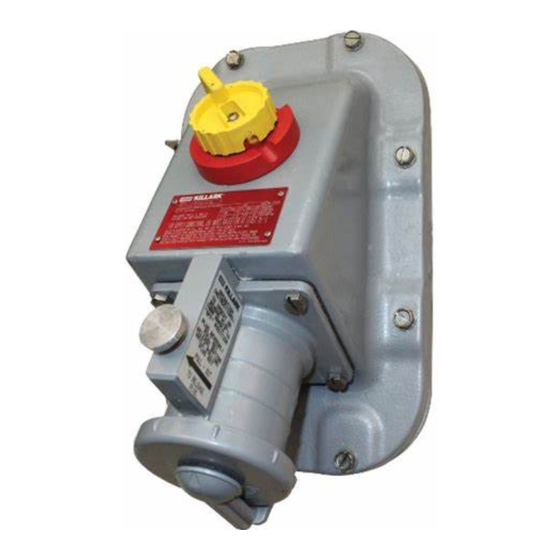
VSQ SERIES 60 AMP INTERLOCKED SWITCHED RECEPTACLES
CLASS I, GROUPS B,C,D; CLASS I ZONE 1, GROUPS IIB, IIA +H
All Installations Must Comply With Applicable Local,
National Electrical Codes, and/or Canadian Electrical
Code.
APPLICATIONS
• VSQ series dead front interlocked receptacle with
switch is suitable for use in hazardous locations.
• Designed for supplying power to fixed or portable
electrical equipment.
ELECTRICAL RATING
• Maximum
voltage
Continuous Current - 60Amperes.
INSTALLATION
• Carefully
Read
and
instructions before installation & operation of this
device.
• Note: All Installations must comply with Applicable
Local, National Electrical Code and/or Canadian
Electrical Code.
• Note: VSQ covers can not be used on VWSQ
mounting boxes, which are intended for non-
hazardous location installations.
• Warning: Make sure the receptacle assembly is
suitable for use in desired location per applicable local
and/or National Electrical Code. Serious damage
and/or
injuries
may
applications. Electrical power must be turned OFF
before and during the installation & maintenance.
Fatal injury
and/or damage may
following these instructions.
• Mounting Arrangement: Receptacle assembly must
be mounted securely onto a column, wall, or other
structure that is able to support the device and the
associated conduit system. The structure is to be
prepared for use of four (4) 3/8" steel bolts (furnished
by others) using the lugs on the housing. The
spacings are as shown in Fig. 1. The device is
equipped with factory installed hinges. It must be
mounted with the hinges on the left and the receptacle
in the downward direction.
• Conduit Installation:
1. 1 1/2" NPT conduit entries are provided on the top
and bottom of the housing.
2. All conduit entries must be sealed within 18" of the
enclosure as per National Electrical Code.
3. Make sure conduit entries are clean before
installing conduit, close-up plugs, reducers, etc.
Killark "LUBG" thread lubricant is recommended for
this application.
P/N 00912317 FORM NO. K1218 R0916 ECO 7-023-16
HAZARDOUS LOCATION ENCLOSURE TYPES 3, 4, 4X & 12.
-
600
VAC
@
50-400Hz.
understand
the
following
result
due
to
improper
result by
; CLASS II, GROUPS F & G; & CLASS III
2
To Prevent Ignition of Hazardous Atmospheres Do Not
Use in Class II, Group E Locations that Contain
Electrically Conductive Dusts.
Warning: Use only copper cable or wire for the range
indicated in the table. Use 75°C rated conductors
(minimum).
Wire Range
Switch
#6 - #4
Ground
#16 - #6
• Wiring:
1. Develop and establish the wiring pattern for your
system. Locations having different voltages and/or
frequencies
attachment plugs. Always test before energizing.
2. Make sure to pull sufficient length of supply
conductors to connect to the enclosed terminals.
3. Strip the conductors to the length shown in table.
4. Connect the conductors to the ground and phase
terminals securely and tighten to the values shown in
the table.
• Inspect & Clean Flange: The machined flange
surface of both the box and cover must be smooth,
free of nicks, scratches, dirt, or any foreign particle
build-up that would prevent proper seating. Surfaces
must seat fully against each other to provide a proper
flame path joint. Clean surfaces by wiping with a
clean, lint free cloth. Apply a light coating of "LUBG"
lubricant to flange surface.
not
• Cover Securement: Close the cover then install and
tighten all cover bolts to 25 ft.-lb. Make sure no cover
bolts are omitted. Use only those bolts supplied with
the device. Check the bolted joint with a .0015" feeler
gauge. The gauge must not enter the joint more than
1/8" at any point.
• Caution: Missing bolts or an improper joint can result
in an explosion, creating the potential for serious or
fatal physical injury and/or property damage.
• Cover
Replacement:
disconnected before removing the cover. Remove the
bolts and reverse the wiring procedure. Once the
conductors have been detached, remove the screws
that hold the cover to the hinges (4 total). Line up the
new cover with the hinges and reinstall the hinge
screws. Once the hinges are attached repeat the
wiring, inspect & clean flange and cover securement
procedures.
HUBBELL INCORPORATED (Delaware)
2112 Fenton Logistics Park Blvd
Fenton, Missouri 63026 USA
Strip Length
0.750 inches
0.500 inches
must
not
have
The
power
Torque
30 in.-lb.
30 in.-lb.
interchangeable
must
be
Side 1 of 2
Advertisement
Table of Contents

Subscribe to Our Youtube Channel
Related Manuals for Hubbell KILLARK VSQ Series


Summary of Contents for Hubbell KILLARK VSQ Series
- Page 1 HUBBELL INCORPORATED (Delaware) 2112 Fenton Logistics Park Blvd Fenton, Missouri 63026 USA INSTALLATION, OPERATION & MAINTENANCE DATA SHEET VSQ SERIES 60 AMP INTERLOCKED SWITCHED RECEPTACLES CLASS I, GROUPS B,C,D; CLASS I ZONE 1, GROUPS IIB, IIA +H ; CLASS II, GROUPS F & G; & CLASS III HAZARDOUS LOCATION ENCLOSURE TYPES 3, 4, 4X &...
- Page 2 OPERATION • Inspect receptacle thread used for plug locking ring • Caution: The switch cannot be turned ON without for proper lubrication. Apply Killark “LUBG” type fully inserting an approved plug (see list below). A lubricant or equivalent to thread surfaces as required plug cannot be inserted or withdrawn unless the to prevent galling between the receptacle and locking switch is OFF.
Need help?
Do you have a question about the KILLARK VSQ Series and is the answer not in the manual?
Questions and answers