Sign In
Upload
Manuals
Brands
Hubbell Manuals
Lighting Equipment
M-7679 R-PAC
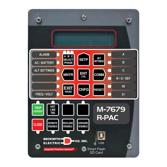
Hubbell M-7679 R-PAC Lighting Equipment Manuals
Manuals and User Guides for Hubbell M-7679 R-PAC Lighting Equipment. We have
1
Hubbell M-7679 R-PAC Lighting Equipment manual available for free PDF download: Instruction Book
Hubbell M-7679 R-PAC Instruction Book (474 pages)
Brand:
Hubbell
| Category:
Lighting Equipment
| Size: 8 MB
Table of Contents
Table of Contents
47
Chapter 1 Introduction
71
Instruction Book Contents
71
General Overview of M-7679 R-PAC
72
Communication Ports
73
Communications Protocols
73
S-7600 Ipscom Communications Software
73
Accessories
74
M-24Xx Recloser Control Adapter Chassis
74
M-2979 Recloser Control Cabinet
74
Table 1-1 M-7679 R-PAC Device Functions
74
Chapter 2 Front Panel Operation
75
Display
75
HMI Startup Screens
75
LCD Screen Contrast
75
Overview
75
Power up Screens
75
Custom Messages
76
Default Message Screens
76
Fault Recorder Event Message
76
HMI Message Screens
76
Wake up Message Screens
76
Compliance with 2020 California Password Law
77
Front Panel Controls and Indicators Overview
77
NERC/CIP Compliant Cyber Security
77
Table 2-1 Permissions Implemented for IEEE 1686 Standard
77
Default Operation Pushbuttons
78
Navigation Pushbuttons
78
Figure 2-1 M-7679 R-PAC Front Panel with Factory Default Pushbutton and LED Labels
79
Figure 2-2 Pushbutton and Tricolor LED Location Index
79
S1 - SELECT PHASE Pushbutton (Leds 21, 22, 23)
80
S10 - Trip Lockout (Led 13)
80
S3 - Alternate Settings
80
S9 - Reset/Lamp Test
80
S11 - Hot Line Tag (Led 14)
81
S12 and S13 - Unassigned (LED 15 and LED 16)
81
S14 - Close (Led 17)
81
S15 - Remote Disable (Led 18)
81
Alarm Led (Led 1)
82
Default LEDS
82
S16 - Reclose Disable (Led 19)
82
S17 - Ground Disable (Led 20)
82
Ac/Battery (Led 2)
83
Alt Settings (Led 3)
83
Chapter 2 Front Panel Operation (Cont.)
83
Freq/Volt (Led 6)
83
Led 11)
83
Led 12)
83
N/G/Sef (Led 10)
83
Phase A, B, C (Led 7, 8, 9)
83
Select Phase (Led 21, 22, 23)
83
Unassigned (Leds 4 and 5)
83
Data Entry Screens
84
EDIT" Mode Prompt
84
ENT Pushbutton
84
EXIT Pushbutton
84
HMI Menu Structure
84
Figure 2-3 HMI Menu Structure and Navigation Example
85
User Lines
86
System Clock
87
Accessing the HMI Monitor Screens
88
Monitor - Metering and Status
88
Loading Settings Files from a Smart Flash SD Card
89
Smart Flash SD Card
89
Firmware Update from a Smart Flash SD Card
91
Saving Settings Files to a Smart Flash SD Card
91
Saving Data Files to a Smart Flash SD Card
92
Chapter 3 System Application & Function Setpoints
93
Overview
93
M-7679 R-PAC System Setup
94
M-7679 R-PAC System Setup from Ipscom
94
System Setup
94
Figure 3-1 System Setup, Voltage Input H6, L6 or X6 (Independent Phase Capable)
95
Interrupter Rated Short Circuit Current
95
Phase Angle Reference
95
Source Orientation Setting with LEA Hardware Options H6, L6 or X6
95
79 Global Operation Mode
96
CT Polarity Reversal Enable
96
Figure 3-2 Use 79 Global Operation Mode (Independent Phase Capable)
96
Table 3-1 Operation Mode - TM (Trip Mode) and LM (Lockout Mode) DNP
96
69 Switch Operation
97
Figure 3-3 View Independent Phase Settings Checkbox (50P Example)
97
Figure 3-4 System Setup Screen - 69 Switch Operation
97
Table 3-2 69 Switch Operation - Three Phase Ganged Recloser
98
Table 3-3 69 Switch Operation (Three Phase) - Independent Phase Capable
98
Table 3-4 69 Switch Operation (Single Phase) - Independent Phase Capable
98
Table 3-5 69 Switch Operation (Single Phase) - Global Operation Mode 3T3LO
99
Table 3-6 69 Switch Operation (Single Phase) - Global Operation Mode 1T1LO, 1T3LO, or 3T1LO)
99
Table 3-7 Analog Hardware Voltage Input Options
100
Voltage Input Configuration
100
Figure 3-5 Voltage Input Configuration LEA Hardware Option H6
101
Figure 3-6 LEA Calibration Screen
101
LEA Calibration Voltage from Ipscom
101
Voltage Input Configuration Settings
101
LEA Output Voltage Calculation
102
Nominal Voltage Configuration - LEA Options H4, L4, X4, H6, L6 and X6
102
Phase Angle Shift Compensation
103
Figure 3-7 RCF Auto Adjustment Screen
104
Figure 3-8 Voltage Input Configuration Screen after RCF Auto Adjustment
104
Ratio Correction Factor (RCF) Auto Adjustment
104
Dual VT Configuration
105
Phantom Voltage - VT Configuration
105
Table 3-8 Phantom Voltage VT Configuration Table
105
Figure 3-10 Open Delta AB Connection Example Diagram
106
Figure 3-11 Open Delta BC Connection Example Diagram
106
Figure 3-9 Open Delta CA Connection Example Diagram
106
Open Delta - VT Configuration
106
Chapter 3 System Application & Function Setpoints (Cont.)
107
Frequency Calculation & Frequency Functions with LEA Hardware H6, L6 or X6
107
LEA Metering with LEA Hardware H6, L6 or X6
107
Open Delta Configuration Table
107
Protective Function Settings with LEA Hardware H6, L6 or X6
107
Table 3-9 Open Delta Configuration Table
107
Figure 3-12 Interface Type - Three-Phase Ganged Options
108
Figure 3-13 Interface Type - Independent Phase Capable Options
108
Figure 3-14 Interface Configurator Manufacturer Options
108
Interface Configurator
108
Coordination of Terminal Phase Assignment with Digital Inputs/Outputs
109
Figure 3-15 32B Multi Recloser Interface - Terminal Phase Assignment Message
109
Table 3-10 32B Multi Recloser Interface Terminal Phase Assignment I/O Table
109
Figure 3-16 CUSTOM Interface Type - Mismatch Allowed Warning Screen
110
Table 3-11 42B Multi Recloser Interface Terminal Phase Assignment I/O Table
110
Figure 3-17 Interface Type CUSTOM - Terminal Phase Assignment Message
111
Figure 3-18 Interface Type (All Others) - Terminal Phase Assignment Message
111
Interface Configurator - Connected Mode
111
Figure 3-19 M-2034 Output Channel Switch Location
112
Interface Configurator - File Mode
112
Special Considerations: Interface Type 42B Tavrida OSM Al_4 and Al_2
112
Figure 3-20 System Setup - Input Tab (with Extended I/O Three-Phase Ganged)
113
Manually Setting the System Inputs
113
Figure 3-21 52B Phantom Digital Inputs
114
Table 3-12 System Inputs - Three Phase Ganged
115
Table 3-13 System Inputs - Independent Phase Capable
116
Virtual Inputs
116
Figure 3-22 System Setup - Virtual Input Tab
117
Profile Switching by Inputs
117
Table 3-14 Profile Switching Inputs Logic
117
Figure 3-23 System Setup - Output Tab (with Extended I/O Three-Phase Ganged)
118
Manually Setting the System Outputs
118
Table 3-15 System Outputs - Three Phase Ganged
119
Independent Pole Operation
120
Table 3-16 System Outputs - Independent Phase Capable
120
Figure 3-24 System Setup - User Lines Tab
121
Figure 3-25 User Lines - SGI Custom Definition Example
121
Setting the User Lines
121
Figure 3-26 System Setup - File Identifier Tab
122
File Identifier
122
Figure 3-27 One-Line Functional Diagram
123
System Diagrams
123
Figure 3-28 Three-Line Connection Diagram
124
LEA Common Settings
125
LEA Configuration from the HMI
125
System Configuration
125
System Configuration from the HMI
125
LEA y Side Settings
126
LEA Z Side Settings
127
Copy Profiles
128
Function Setpoints
128
Recloser Wizard
128
Selecting the Active Setpoint Profile
128
Setpoint Profiles
128
Utilizing the Smart Flash SD Card to Save and Load Setpoint Files
128
Comparing Setpoint Files
129
Figure 3-29 Ipscom Setpoint File Compare Results Screen
129
Configuring Functions
130
Loop Scheme Application
130
Table 3-17 Available Functions
130
Figure 3-30 Typical Function Setpoints Main Screen
131
Setup/Setpoints
131
25 Sync Check
132
Figure 3-31 Function 25 Voltage Sources
132
Sync Check Permission (25S)
132
Undervoltage Permission (25D)
132
Figure 3-32 Function 25 Sync Check Setpoints Screen
133
Figure 3-33 Function 25 Sync Check Logic Diagram
133
27 Phase Undervoltage
134
27PP Phase-To-Phase Undervoltage
134
Figure 3-34 Function 27 Phase Undervoltage Setpoint Screen (Shown: Three-Phase Ganged)
134
Figure 3-35 Function 27PP Phase-To-Phase Undervoltage Setpoints (Three-Phase Ganged)
134
27 Vz1 Undervoltage
135
32 Directional Power
135
Directional Choice
135
Figure 3-36 Function 27Vz1 Undervoltage Setpoints Screen
135
Figure 3-37 Directional Power Flow
135
46DT Negative-Sequence Definite Time Overcurrent
136
Figure 3-38 Directional Power Configurations
136
Figure 3-39 Function 32 Directional Power Setpoints Screen
136
Figure 3-40 Function 46DT Negative-Sequence Definite Time Overcurrent Setpoints Screen
136
46IT Negative-Sequence Inverse Time Overcurrent
137
Figure 3-41 Function 46IT Negative-Sequence Inverse Time Overcurrent Setpoints Screen
137
Figure 3-42 Custom Curves Interactive Screen
137
User Defined Custom Curves
137
46BC Broken Conductor Detection
138
Figure 3-43 Function 46BC Logic Diagram
138
Figure 3-44 Function 46BC Broken Conductor Detection Setpoints Screen
138
47 Negative-Sequence Overvoltage
139
50P Phase Instantaneous/Definite Time Overcurrent
139
Figure 3-45 Function 47 Negative-Sequence Overvoltage Setpoints Screen
139
Figure 3-46 Function 50P Phase Instantaneous/Definite Time Overcurrent Setpoints Screen (Shown: Three Phase Ganged)
139
High Current Lockout (HCL)
139
50G Ground Instantaneous/Definite Time Overcurrent
140
50N Residual Instantaneous/Definite Time Overcurrent
140
Figure 3-47 Function 50G Ground Instantaneous/Definite Time Overcurrent Setpoints Screen
140
High Current Lockout (HCL)
140
50GS High Current Lockout (HCL)
141
50GS Sensitive Ground Instantaneous/Definite Time Overcurrent
141
Figure 3-48 Function 50N Residual Instantaneous/Definite Time Overcurrent Setpoints Screen
141
Figure 3-49 Function 50GS Ground Sensitive Overcurrent Setpoints Screen
141
50BF Breaker Failure
142
Figure 3-50 Breaker Failure Logic Diagram
142
Figure 3-51 Function 50BF Breaker Failure Setpoints Screen
142
51V Phase Inverse Time Overcurrent with Voltage Control or Voltage Restraint
143
Figure 3-52 51P Voltage Restraint Characteristic
143
Figure 3-53 Inverse Time Overcurrent Characteristic
144
Figure 3-54 Function 51P/51V Phase Inverse Time Overcurrent with Voltage Control/Restraint Setpoints Screen (Shown: Three Phase Ganged)
144
Table 3-18 M-7679 Curve Selection
144
51G Ground Inverse Time Overcurrent
145
51N Residual Inverse Time Overcurrent
145
Figure 3-55 Function 51N Residual Inverse Time Overcurrent Setpoints Screen
145
Figure 3-56 Function 51G Ground Inverse Time Overcurrent Setpoints Screen
145
51GS Sensitive Ground Inverse Time Overcurrent
146
59 Phase Overvoltage
146
Figure 3-57 Function 51GS Sensitive Ground Inverse Time Overcurrent Setpoints Screen
146
Figure 3-58 Function 59 Phase Overvoltage Setpoints Screen (Shown: Three Phase Ganged)
146
59I Peak Overvoltage
147
59N Residual Overvoltage
147
59PP Phase-To-Phase Overvoltage
147
Figure 3-59 Function 59PP Phase-To-Phase Overvoltage Setpoints Screen (Shown: Three Phase Ganged)
147
Figure 3-60 Function 59N Residual Overvoltage Setpoints Screen
147
59Vz1 Overvoltage
148
Figure 3-61 Function 59I Peak Overvoltage Setpoints Screen (Shown: Three Phase Ganged)
148
Figure 3-62 Vz1 Broken Delta Connection
148
Figure 3-63 Function 59Vz1 Overvoltage Setpoints Screen
148
67P Phase Directional Overcurrent
149
Definite/Inverse Time Characteristic
149
Figure 3-64 67P Phase Directional Overcurrent - Directional Characteristic
149
Minimum Polarization Voltage
149
Figure 3-65 67P Directional Characteristic with Angle Band Enabled
150
Figure 3-66 Function 67P Directional Overcurrent Definite Time Setpoints Screen
150
67 Directionality View
151
Figure 3-67 Function 67P Directional Overcurrent Inverse Time Setpoints Screen
151
Figure 3-68 Function 67 Directionality View Default MSA
151
67N Residual Directional Overcurrent
152
Definite/Inverse Time Characteristic
152
Figure 3-69 Function 67 Directionality View Default MSA and Angle Band
152
Minimum Polarization Voltage
152
Figure 3-70 67N Residual Directional Overcurrent Definite Time Setpoints Screen
153
Figure 3-71 67N Residual Directional Overcurrent Inverse Time Setpoints Screen
153
Figure 3-72 67N Residual Directional Overcurrent - Directional Characteristic
154
Figure 3-73 67N Residual Directional Overcurrent - Polarizing Voltage (V ) and
154
67G Ground Directional Overcurrent
155
Definite/Inverse Time Characteristic
155
Figure 3-74 67G Ground Directional Overcurrent - Directional Characteristic
155
Minimum Polarization Voltage
155
Figure 3-75 67G Ground Directional Overcurrent - Polarizing Voltage and
156
Figure 3-76 67G Broken Delta Polarizing Source
156
Figure 3-77 67G Ground Directional Overcurrent Definite Time Setpoints Screen
157
Figure 3-78 67G Ground Directional Overcurrent Inverse Time Setpoints Screen
157
67Q Negative-Sequence Directional Overcurrent
158
Definite/Inverse Time Characteristic
158
Figure 3-79 67Q Negative-Sequence Directional Overcurrent Definite Time Setpoints Screen
158
Minimum Polarization Voltage
158
Figure 3-80 67Q Negative-Sequence Directional Overcurrent Inverse Time Setpoints Screen
159
Figure 3-81 67Q Negative-Sequence Directional Overcurrent - Directional Characteristic
159
67GS Sensitive Ground Directional Overcurrent
160
Definite/Inverse Time Characteristic
160
Figure 3-82 67Q Negative-Sequence Directional Overcurrent - Polarizing Voltage
160
Minimum Polarization Voltage
160
Figure 3-83 67GS Sensitive Ground Directional Overcurrent Definite Time Setpoints Screen
161
Figure 3-84 67GS Sensitive Ground Directional Overcurrent Inverse Time Setpoints Screen
161
81 Frequency
162
Figure 3-85 81 Hysteresis
162
Hysteresis
162
Minimum Load
162
Undervoltage Block
162
Figure 3-86 Function 81 Frequency Setpoints Screen
163
Figure 3-87 Example of (81) Frequency Trip Characteristics
163
81R Rate-Of-Change of Frequency
164
CLP Cold Load Pickup
164
Figure 3-88 81R Rate-Of-Change of Frequency Setpoints Screen
164
Cold Load Pickup Active State
165
Cold Load Pickup Arming State
165
Figure 3-89 Cold Load Pickup Arming Logic Diagram
165
Cold Load Pickup Restore to Normal State
166
Figure 3-90 Cold Load Pickup Activation Logic Diagram
166
Figure 3-91 Cold Load Pickup Reset Logic Diagram
166
Cold Load Pickup Setpoints
167
Figure 3-92 Cold Load Pickup below Minimum to Trip Restore Logic Diagram
167
Figure 3-93 Cold Load Pickup Setpoints - Timers Tab
167
Figure 3-94 Cold Load Pickup Setpoints - Inst./Def. Time Overcurrent (Three Phase Ganged)
168
Figure 3-95 Cold Load Pickup Setpoints - Inverse Time Overcurrent (Three Phase Ganged)
168
Figure 3-96 Cold Load Pickup Logic Diagram
169
Figure 3-97 HLT - Hot Line Tag Setpoints Screen (Partial)
170
HLT Hot Line Tag
170
Auto Restoration Settings
171
Restore Auto Restoration
171
Figure 3-98 Auto Restoration Setpoints Screen
172
Figure 3-99 Auto Restoration Conceptual Logic Diagram
172
Figure 3-100 Ipslogic Setpoints Screen
173
Ipslogic
173
Ipslogic Close Block Action
173
Ipslogic Custom Messages
173
Ipslogic Setpoints
173
Figure 3-101 Ipslogic Editor Screen
174
Figure 3-102 Ipslogic Editor Input Selection Screen
174
Programming Ipslogic
174
Chapter 3 System Application & Function Setpoints (Cont.)
175
Figure 3-103 Ipslogic Editor "Gates" Tool
175
Figure 3-104 Ipslogic Editor Oscilloscope Tool
175
Figure 3-105 Load Encroachment Logic Diagram
176
Figure 3-106 Load Encroachment Logic Setpoints Screen
176
Figure 3-107 Load Encroachment Logic Application
176
LEL Load Encroachment Logic
176
Figure 3-108 Load Encroachment Logic Graph
177
Figure 3-109 LEL Directional Element F67P #1 Selected
177
LEL Directional Element F67
177
Load Encroachment Logic Graph
177
BM Breaker Monitor
178
Figure 3-110 LEL Directional Element F67P #1 Resultant Setpoints Screen
178
Figure 3-111 Breaker Accumulator Status Screen
178
Figure 3-112 Breaker Accumulator Status Screen - Timing Selection Method
179
Figure 3-113 System Setup, Interrupter Rated Short Circuit Current Setting
179
Figure 3-114 Breaker Monitor Common Setpoints Tab
180
Figure 3-115 Breaker Monitor Element #1 Setpoints Tab
180
Figure 3-116 Breaker Accumulator - Switching Life Curves Graph
181
Figure 3-117 Inrush Harmonic Restraint Setpoints Screen
181
Figure 3-118 Use Inrush Harmonic Block Checkbox
181
IHR Inrush Harmonic Restraint
181
Figure 3-119 Inrush Harmonic Restraint Logic Diagram
182
79 Lockout Feature
183
79 Recloser Relay
183
Figure 3-120 Recloser Transition State Diagram
183
Figure 3-121 79 Drive to Lockout HCL Function Selection Tab
183
Trip and Close Logic
183
79 Supervision Feature
184
Figure 3-122 Supervision Functions Tab
184
Terminology
184
Breaker Status Truth Table
185
Table 3-19 Relay Status Input Levels
185
Table 3-20 Relay Status Input Levels with Common 52B/69 Lockout
185
Figure 3-123 Function 79 Lockout Algorithm Diagram (Three-Phase Ganged)
186
Figure 3-124 Function 79 Lockout Algorithm Diagram (Independent Phase)
187
Table 3-21 Default Front Panel LED Display During a Reclose Cycle
187
Figure 3-125 Tripping of the Breaker (Timing Diagram)
188
Phase Count and Ground Count Exceeded Lockout Algorithm
188
Sequence Coordination
188
External Operation
189
Figure 3-126 Reset Time from Lockout after Manual Close
189
79 Recloser Status Monitoring
190
Figure 3-127 Recloser Status Monitoring Screen - Example
190
Recloser Status Monitoring/Fault Duration
190
79 Recloser Relay Setpoints
191
Figure 3-128 79 Recloser Relay Setpoints (Independent Phase Operation 1T1LO)
191
79 Logic to Start Recloser Timer
192
79 Recloser Relay Skip Shot
192
Figure 3-129 79 Recloser Relay Target Reset Timer Settings
192
Figure 3-130 79 Recloser Relay Skipshot Settings Screen
192
Figure 3-131 79 Recloser Relay Logic to Start Recloser Timer Settings Screen
192
Resetting Targets
192
79 Trip Reclose Sequence
193
Figure 3-132 Function 79 Sequence - Trip Reclose Sequence
193
Figure 3-133 79 Sequence - Element Disabled Popup Screen
193
Figure 3-134 79 Sequence - Element Removed Warning Message
193
27 Bus Side Voltage Supervision Setpoints
194
Beckwith Fast and Slow Curve Implementation
194
Figure 3-135 Recloser Relay Function 27 Bus Side Voltage Supervision Setpoints
194
Figure 3-136 Auto Reclose Single Shot Timing with 27BSVS Enabled
194
Figure 3-137 79 Recloser Relay Fast & Slow Curve Qualifiers Settings Screen
195
Figure 3-138 Recloser Status Monitoring Screen - Fast/Slow Curve Selection
195
Figure 3-139 Time Modifier Settings Screen
196
Figure 3-140 Recloser Wizard Common Settings Screen
197
Recloser Wizard
197
Recloser Wizard Common Settings Screen
197
Figure 3-141 Recloser Wizard Profile Screen
198
Figure 3-142 Recloser Wizard Phase Overcurrent Settings Screen
198
Recloser Wizard Phase Overcurrent Settings Screen
198
Recloser Wizard Profile Screen
198
Figure 3-143 Recloser Wizard Display All Graphs Feature
199
Figure 3-144 Recloser Wizard Ground Overcurrent Settings Screen
199
Recloser Wizard Ground Overcurrent Settings Screen
199
Figure 3-145 Ground Precedence Flowchart
200
Figure 3-146 Recloser Wizard Residual (Neutral) Overcurrent Settings Screen
201
Figure 3-147 Recloser Wizard Hot Line Tag Settings Screen
201
Recloser Wizard Hot Line Tag Settings Screen
201
Recloser Wizard Residual (Neutral) Overcurrent Settings Screen
201
Figure 3-148 Recloser Wizard Automatic Reclosing Screen
202
Figure 3-149 79 Drive to Lockout Screen
202
Recloser Wizard Automatic Reclosing Settings Screen
202
Figure 3-150 79 Supervision Functions Screen
203
Figure 3-151 Navigation Panel Screen
203
Navigation Panel Screen
203
3T3LO - Three-Phase Trip and Three-Phase Lockout
204
Independent Phase Operation Mode
204
Populate Values to All Three Phases Settings
204
1T1LO - Single-Phase Trip and Single-Phase Lockout
205
1T3LO - Single-Phase Trip and Three-Phase Lockout
205
3T1LO - Three-Phase Trip and Single-Phase Lockout
205
Figure 3-152 Ground Function Active Feature
206
Ground (G)/Residual (N) Deactivate
206
Ground/Neutral Trip 3T-3LO Only
206
Phase Identification
206
Trip All Phases for Multi-Phase Faults
206
Recloser Wizard Independent Phase Mode
207
Sectionalizer Operation
207
Switch/Sectionalizer Application
207
Switch/Sectionalizer Mode
207
Figure 3-153 Setpoints Screen with Switch/Sectionalizer Option
208
Figure 3-154 Sectionalizer Setpoints Screen
208
Figure 3-155 Sectionalizer - Sequence Coordination Mode Example
209
Figure 3-156 Sectionalizer Sequence Coordination Warning Message
209
Figure 3-157 Sectionalizer Setpoints: Independent Phase Capable Operation Mode
210
Figure 3-158 Sectionalizer Screen: Target Reset Timer Settings
211
Figure 3-159 Sectionalizer Screen: Trigger Selections
211
Figure 3-160 Sectionalizer Fault Current Only Trigger Logic Diagram
212
Figure 3-161 Sectionalizer Voltage Loss Only Logic Diagram
212
Figure 3-162 Sectionalizer Current with Voltage Loss Trigger Logic Diagram
213
Figure 3-163 Inrush Current Restraint Diagram
214
Figure 3-164 Sectionalizer Screen: Inrush Current Restraint Settings (Three-Phase Ganged)
214
Chapter 3 System Application & Function Setpoints (Cont.)
215
Figure 3-165 Sectionalizer Monitoring Screen
215
Figure 3-166 Sectionalizer Screen: "Enable Switch Mode" Selection
215
Switch Mode
215
3.10 Loop Scheme Application
216
Figure 3-167 Loop Scheme with Two Reclosers
216
Figure 3-168 Loop Scheme with Three Reclosers
217
Figure 3-169 Loop Scheme with Five Reclosers
217
Figure 3-170 Loop Scheme with Midpoint Recloser Application
218
Figure 3-171 Loop Scheme with Tie Recloser Application
218
Figure 3-172 General Loop Scheme States Overview Diagram
219
Loop Scheme Diagrams
219
Figure 3-173 Loop Scheme - Dead Line and Live Line (y and Z) Logic Diagram
220
Loop Scheme Voltage Control Logic
220
Figure 3-174 Sectionalizing and Midpoint Recloser Dead Line Logic Diagram
221
Sectionalizing and Midpoint Recloser Dead Line Logic
221
Figure 3-175 Sectionalizing Recloser Voltage Restore Confirm Logic Diagram
222
Sectionalizing Recloser Voltage Restore Confirm Logic
222
Figure 3-176 Sectionalizing Recloser Live Line Logic Diagram
223
Sectionalizing Recloser Live Line Logic
223
Figure 3-177 Midpoint Recloser Live Line Logic Diagram
224
Figure 3-178 Sectionalizing and Midpoint Recloser Reset Logic Diagram
224
Midpoint Recloser Live Line Logic
224
Sectionalizing and Midpoint Recloser Reset Logic
224
After Loop Scheme Logic
225
Figure 3-179 after Loop Scheme Logic Diagram
225
Figure 3-180 Lockout State Logic Diagram
225
Lockout State Logic
225
Figure 3-181 Tie Recloser Dead Line and Live Line Logic Diagram
226
Tie Recloser Dead Line and Live Line Logic
226
Figure 3-182 Tie Recloser Reset Logic Diagram
227
Figure 3-183 Tie Recloser Supervision Logic Diagram
227
Tie Recloser Reset Logic
227
Tie Recloser Supervision Logic
227
Figure 3-184 System Setup Screen - Source Orientation Selection
228
Loop Scheme - Ipscom Settings
228
Figure 3-185 Ipscom Loop Scheme Sectionalizing Recloser Setpoints Screen
229
Sectionalizing Recloser
229
Figure 3-186 Ipscom Loop Scheme Midpoint Recloser Setpoints Screen
230
Midpoint Recloser
230
Figure 3-187 Ipscom Loop Scheme Tie Recloser Setpoints Screen
231
Tie Recloser
231
Figure 3-188 Loop Scheme Monitoring - Individual Phase Breaker Status Display
232
Figure 3-189 Loop Scheme Monitoring - Trip and Lockout Mode Status Display
232
Loop Scheme Monitoring
232
3.11 Common Setpoints
233
Battery Charger Monitor
233
Figure 3-190 PSBC - IED Power Supply/Battery Charger Monitor Setpoints Screen
233
IED Power Supply Monitor
233
PSBC IED Power Supply/Battery Charger Monitor
233
Table 3-22 Power Supply Monitor Voltage Setting Ranges
233
Figure 3-191 M-2035 Analog Inputs Threshold Setpoints Screen
234
Figure 3-192 TCM/CCM - Trip/Close Circuit Monitor Setpoints Screen
234
M-2035 Analog Inputs Threshold Setpoints
234
TCCM Trip/Close Circuit Monitoring
234
Trip Circuit Monitor
234
Close Circuit Monitor
235
Figure 3-193 Trip Circuit Monitoring Input
235
Figure 3-194 Recommended Close Circuit Monitoring Input Configuration
236
Figure 3-195 Close Circuit Monitoring Input Configuration with Anti-Pump Relay Not Bypassed
236
60FL VT Fuse Loss
237
External Fuse-Loss Function
237
Figure 3-196 Function 60FL Fuse Loss Setpoints Screen
237
Internal Fuse Loss Detection Logic
237
Figure 3-197 Fuse Loss (60FL) Function Logic
238
Figure 3-198 Demand Metering Screen (I L Section)
239
TDD Calculation
239
THD Calculation
239
THD/TDD Total Harmonic Distortion/Total Demand Distortion
239
Figure 3-199 THD/TDD Setpoints Screen with Independent Phase Enabled (Partial)
240
Close Block Function
241
Figure 3-200 Close Block Setpoints Screen
241
Figure 3-201 Remote Control Screen - Close Block Override Command
241
Figure 3-202 Recloser Status Monitoring Screen - Close Block Status and Override Command
242
Figure 3-203 Close Block Function Logic Diagram
242
Figure 3-204 SGI Logic Diagram
243
SGI - Sensitive Ground Indicator
243
Table 3-23 SEF Ground Current Input Specifications
243
Figure 3-205 SGI - Sensitive Ground Indicator Setpoints Screen
244
Figure 3-206 SGI - Harmonic Trigger Setup Screen
244
Voltage and Current Harmonics
244
Figure 3-207 Harmonic Targets Monitor Screen
245
Figure 3-208 SGI - SEF Fundamental Signal 50GS #1 Settings Group Screen
245
SEF Fundamental Signal
245
Custom Supervision and Initiation Logic
246
Figure 3-209 SGI - IPS Global Logic Setpoints Screen
246
Figure 3-210 SF6 Voltage Pressure Sensor Settings Screen
246
Pressure Sensor
246
SF6 Pressure Sensor - SF6 Voltage
246
Figure 3-211 Battery Charger M-2032B-SF6 Voltage Selection
247
Figure 3-212 System Setup/Input Selection with SF6 Contact
247
Running on Battery During AC Power Loss
247
SF6 Pressure Sensor - SF6 Contact
247
Figure 3-213 Analog Output Module Customer Load Connection Options
248
Optional Analog Output Module
248
Typical Customer Connections
248
Analog Output Setpoints
249
Chapter 3 System Application & Function Setpoints (Cont.)
249
Enabling the Analog Output Module
249
Figure 3-214 Enable Analog Output Module - Setup Comm Port 1 Screen
249
Figure 3-215 Analog Output Settings Screen
249
Figure 3-216 Measured Variable Parameter Selection List
250
3.12 Configuring Setpoints from the HMI
251
Selecting a Profile for Editing
251
Setting Overcurrent Functions
251
Example: Setting 50P, Element #1, Three-Phase Ganged Operation Mode
252
Setting 79 Recloser Relay (Three-Phase Ganged)
253
Setting 79 Recloser Relay Common Settings (Independent Phase Mode)
254
Setting 79 Recloser Relay (Independent Phase Mode)
255
Figure 3-217 Option P - New File Setup Screen
256
Single Phase/Two Phase Operation Mode (Option P)
256
Figure 3-218 M-7679 Option P - One-Line Functional Diagram
257
Figure 3-219 Option P - System Setup Screen (Two Pole Operation)
258
Figure 3-220 System Reboot Required Caution Screen
258
System Setup (Option P)
258
Figure 3-221 Terminal Phase Assignment (Terminal 1 and 2 Selected)
259
Figure 3-222 Pole and Phase Assignment Indicator
259
Figure 3-223 Phase Angle Reference Dropdown (Two Pole Operation)
259
Pole and Phase Assignment Indicator
259
Figure 3-224 Voltage Input Configuration L6 (Two Pole Operation, Phase Assignment A-B)
260
Figure 3-225 CUSTOM Interface, Single Pole Terminal 1, Phase Assignment a
260
Figure 3-226 Single Pole Terminal 1, Phase Assignment a - Input Tab
261
Figure 3-227 Single Pole Terminal 1, Phase Assignment a - Output Tab
261
Figure 3-228 Additional Settings (Option P - Two Pole Operation)
261
Functions/Features Exclusive to Option P
261
Figure 3-229 Load Current Present Setpoints (Option P - Two Pole Operation)
262
Figure 3-230 Loss of Sensing Setpoints (Option P - Two Pole Operation)
262
Load Current Present (LCP)
262
Loss of Sensing Detection (LOS)
262
Figure 3-231 Loss of Sensing Logic Diagram (Pole 1 and Pole 2)
263
Figure 3-232 High Current Alarm Setpoints (Option P - Two Pole Operation)
263
High Current Alarm
263
Figure 3-233 Ipscom Setup/Alarms Screen (Option P)
264
Figure 3-234 79 Recloser Relay - Use Pole 1 Settings for both Poles (Combined Tab)
264
Recloser Relay (Option P)
264
Figure 3-235 79 Recloser Relay Setpoints (Option P - Two Pole Operation)
265
Figure 3-236 79 Recloser Relay Ipslogic Selection Dropdown
265
Figure 3-237 Settings Matrix (Option P)
266
Settings Matrix
266
Figure 3-238 Setpoints Screen (Option P)
267
Figure 3-239 Common Setpoints Screen (Option P)
267
Setpoints (Option P)
267
Setpoints Modified for Option P
268
Table 3-24 Function Setpoint Modifications for One or Two Pole Operation (Option P)
268
Figure 3-240 Use Pole 1 Settings for both Poles - Combined Settings Screen
269
Figure 3-241 Function 27 Phase Undervoltage Setpoints (Option P - Two Pole Operation)
269
Setpoints Implementation (Option P)
269
Figure 3-242 Function 27Vzs Undervoltage Setpoints (Option P - Two Pole Operation)
270
Figure 3-243 Function 59 Phase Overvoltage Setpoints (Option P - Two Pole Operation)
270
Figure 3-244 Cold Load Pickup Setpoints (Option P - Two Pole Operation)
271
Figure 3-245 Ipslogic New Status Bits - Function 27 Example (Option P)
271
Figure 3-246 Sectionalizer Setpoints (Option P - Two Pole Operation)
272
Figure 3-247 Sectionalizer Monitoring Screen (Option P - Two Pole Operation)
272
Figure 3-248 Loop Scheme Sectionalizing Recloser Setpoints (Option P - Two Pole Operation)
273
Configuring Option P Setpoints from the HMI
274
Figure 3-249 Loop Scheme Monitoring Screen (Option P - Two Pole Operation)
274
Figure 3-250 Front Panel Button Editor (Option P)
276
Figure 3-251 Front Panel Wake up Screen List (Option P)
276
Setup Menu (Option P)
276
Figure 3-252 Datalog CSV Configuration (Option P)
277
Figure 3-253 Sequence of Events Triggers (Option P)
277
Figure 3-254 Display All Settings Example (Option P)
278
Monitor Menu (Option P)
278
Figure 3-255 Primary Metering Screen (Option P - LEA L6, H6, or X6, Two Pole Operation)
279
Figure 3-256 Function Status Screen (Option P)
279
Figure 3-257 Counters Screen (Option P - Two Pole Operation)
280
Figure 3-258 Recloser Status Monitoring Screen (Option P - Two Pole Operation)
280
Accessing Option P Monitor Screens from the HMI
281
Figure 3-259 Remote Control Screen (Option P - Two Pole Operation)
281
Utility Menu (Option P)
281
Availability
283
Hardware Required for Direct USB (Serial) Communication
283
Hardware Requirements
283
Overview
283
Digital Signature
284
Figure 4-1 Ipscom S-7600 Program-Item Icon
284
Initial Communication Setup
284
Installing Ipscom
284
Starting Ipscom
284
Direct Connection
285
Figure 4-2 M-0243 Null Modem Cable
285
Figure 4-3 Direct Connection Diagram
285
Figure 4-4 USB Port Connection Screen
286
Figure 4-5 Log on User Name and Password Screen
286
Initial Local Communications Using Direct USB Connection
286
Figure 4-6 Setup Comm Port Screen
287
Optional Ethernet Port Setup
287
Serial Comm Port Setup
287
Ethernet Port Setup from Ipscom
288
Figure 4-7 Optional Dual Ethernet Ports
288
Figure 4-8 Setup Ethernet Screen (Shown: Dual Ethernet Option)
288
Figure 4-9 Ipscom Startup Screen Menu Selections
289
Overview of Ipscom Features
289
Figure 4-10 Ipscom Main Screen Menu Selections (1 of 2)
290
Figure 4-11 Ipscom Main Screen Menu Selections (2 of 2)
291
Ipscom Quick Access Toolbar
291
Figure 4-12 Security Banner Setup Screen
292
Figure 4-13 System Alarms Message Screen
292
M-7679 System Alarms Displayed in Ipscom
292
Startup Screen/Utility/Banner Setup
292
Chapter 4 Ipscom Remote Setup and Operation (Cont.)
293
File Menu
293
File Not Open or Not Connected Mode
293
Figure 4-14 New File Setup Screen
294
Communication Menu
296
Communication Menu (Not Connected)
296
Communication/Com Port
296
Communication/Usb
296
Figure 4-16 Serial Port Communication Screen
296
Communication/Tcp/Ip
297
Figure 4-17 TCP/IP Connection Screen
297
Communication Menu (Connected or File Mode)
298
Communication/Disconnect
298
Communication/Setup/Comm Port
298
Communication/Setup/Comm Port Security/Physical Ports
298
Communication/Setup/Ethernet Settings
298
Communication/Setup/Protocol Address
298
Figure 4-18 Enable/Disable Physical Communication Ports Screen
298
Communication/Setup/Comm Port Security/Protocol Access
299
Communication/Setup/Protocol/Iec 61850
299
Figure 4-19 Enable/Disable Protocol Access Screen
299
Figure 4-20 Goose Simulation Enable Screen
300
Figure 4-21 Example of IED Receiving Simulation Signals from M-7679
300
Communication/Setup/Protocol/Dnp
301
Communication/Setup/Protocol/Iec 60870
301
Figure 4-22 IEC 60870 Configuration Editor "Single Points" Screen
301
Figure 4-23 M-7679 DNP Configuration Screen
302
Figure 4-24 DNP Properties Screen
303
Figure 4-25 Radius Configuration Screen
303
Setup/Communication Security/Radius Configuration
303
Figure 4-26 Ipsec General Settings Screen
304
Figure 4-27 Ipsec Log Menu Information Screen
304
Setup/Communication Security/Ipsec Configuration
304
BECO Vhmi - Virtual HMI
305
Figure 4-28 BECO Vhmi Right-Click to Edit Label Feature
305
Monitor Menu
305
Figure 4-29 BECO Vhmi Screen
306
Figure 4-30 Ipscom Primary Metering Screen (Six Voltage Inputs: Option L6, H6, or X6)
307
Monitor/Primary and Secondary Metering
307
Figure 4-31 Phasor Diagram
308
Figure 4-32 Typical Function Status Screen
308
Monitor/Function Status
308
Monitor/Phasor Diagram
308
Figure 4-33 Demand Metering Screen
309
Monitor/Demand Metering
309
Figure 4-34 Demand Metering Power Targets and Corresponding DNP Points
310
Figure 4-35 Demand Metering Power Targets Band Status Diagram
310
Figure 4-36 Harmonic Analysis Screen
311
Monitor/Harmonics
311
Figure 4-37 Sync Scope Monitor Screen
312
Monitor/Counters
312
Monitor/Sync Scope
312
Table 4-1 Overcurrent Fault Detection Counters Logic
313
Figure 4-38 Counters Screen
314
Figure 4-39 Live Oscillograph Display Screen
315
Figure 4-40 Breaker Accumulator Status Screen
315
Monitor/Breaker Accumulator Status
315
Monitor/Live Oscillograph
315
Figure 4-41 M-2035 Analog Inputs Monitoring Screen
316
Figure 4-42 Battery Charger Monitoring Screen
316
Monitor/Function Monitoring
316
Monitor/Harmonic Targets
316
Monitor/M-2035 Analog Inputs (Optional)
316
Figure 4-43 Recloser Status Monitoring Screen (Three-Phase Ganged)
317
Figure 4-44 Sectionalizer Monitoring Screen
317
Figure 4-45 Cold Load Pickup Monitoring Screen
318
Figure 4-46 M-7679 Web Browser Landing Page
318
Status Monitoring Using the Web Browser Interface
318
Configuration/Relay
319
Figure 4-47 System Setup Screen (Shown: Voltage Input L6, Independent Phase Capable)
319
Setup Menu
319
Setup/Configuration
319
Setup/Select Active Profile
319
Configuration/Front Panel Functions
320
Figure 4-48 Front Panel Setup Screen
320
Programmable Pushbuttons Feature
321
Figure 4-49 Pushbutton Information Popup Screen
322
Pushbutton Programming (Initiate Action/Block)
322
Smart Functions
322
Figure 4-50 Button Function Setup "Smart Functions" Screen
323
Front Panel Setup/Remote Disable Pushbuttons
323
Figure 4-51 LED Latch Setup Screen
324
Front Panel Setup/Leds
324
Figure 4-52 LED Editor - Use Comment as Tooltip Example
325
Figure 4-53 LED Editor Screen
325
Figure 4-54 LED Editor Input Selection Screen
326
Programming Leds
326
Table 4-2 Predefined LED Collective Function Input Definitions
327
Configuration/Profile Manager
328
Figure 4-55 Wake up Screen List Selection Screen
328
Front Panel Setup/Wake up Screen List
328
Configuration/Fault Distance Parameters
329
Figure 4-56 Fault Distance Parameters
329
Configuration/Breaker Interrupting Time
330
Fault Type Detection
330
Figure 4-57 Ipscom Fault Type Display
330
Figure 4-58 Breaker Interrupting Time
330
Configuration/Fault Current 1Stt Reset
331
Configuration/Harmonic Trigger
331
Figure 4-59 Fault Current 1Stt Reset Screen
331
Figure 4-60 Recloser Wizard - Recloser Common Settings Screen
331
Setup/Recloser Wizard
331
Figure 4-61 Typical Setpoints Screen
332
Setup/Overcurrent Quick Editor
332
Setup/Setpoints
332
Figure 4-62 Overcurrent Quick Editor Screen
333
Setup/Alarms
333
Figure 4-63 Alarms Screen
334
Figure 4-64 Data Logging Setup Screen
334
Setup/Data Logging
334
Figure 4-65 Datalog CSV Configuration Screen
335
Figure 4-66 Setup Oscillograph Recorder Screen
336
Setup/Oscillograph
336
Figure 4-67 Oscillograph Trigger Selection Screen
337
Figure 4-68 Sequence of Events Setup Screen
338
Setup/Sequence of Events
338
Figure 4-69 Overcurrent Fault Detection Setup Screen Example
339
Setup/Overcurrent Fault Detection
339
Figure 4-70 Overcurrent Fault Detection Triggers, Sectionalizer/Switch Mode
340
Figure 4-71 Display I/O Map Screen
340
Setup/Display I/O Map
340
Figure 4-72 Display All Settings Interactive Screen
341
Setup/Clear All Logged Data
341
Setup/Custom Curve Editor
341
Setup/Display All Settings
341
Figure 4-73 Three-Phase Ganged or Independent Phase Remote Control Screen
342
Utility Menu
342
Utility/Remote Control
342
Figure 4-74 Remote Output Control Screen
343
Hardware/Update Firmware
343
Utility/Hardware
343
Utility/Remote Output Control
343
Hardware/Calibration
344
Hardware/Date & Time Compare
344
Hardware/Set Date & Time
344
Figure 4-75 Front Panel Labels PDF Form - Vertical Model
345
Hardware/Front Panel Labels
345
Hardware/Update Analog out Firmware
345
Hardware/Update M-2035 Firmware
345
Cybersecurity/Manage Accounts
346
Cybersecurity/Sd Card Key Generator
346
Figure 4-76 SD Card Key Generator Screen
346
Utility/Cybersecurity
346
Data Analysis/Soe Viewer/Sequence of Events Viewer
347
Figure 4-77 View Sequence of Events Screen
347
Figure 4-78 Sequence of Events Detailed Record Screen
347
Utility/Data Analysis
347
Data Analysis/Fault Recorder
348
Data Analysis/Message Log
348
Figure 4-79 PQ Events Viewer Screen
348
Data Analysis/Firmware Update Log
349
Data Analysis/Trip Sequence Events
349
Figure 4-80 Trip Sequence Viewer Screen (Shown: Independent Phase Example)
349
Data Analysis/Becoplot
350
Data Analysis/Ftp Download Converter
350
Data Analysis/Sd Card Download Converter
350
Utility/Remote Reboot
350
Utility/View PPF Details
350
4.10 Help Menu
351
Help/About
351
Help/Information
351
4.11 Becoplot Analysis Software
352
Help/E-Mail Support
352
Overview
352
Starting Becoplot
352
Figure 4-81 Becoplot Main Window with Submenus
353
Figure 4-82 Becoplot Window with Data Logging Data Example with Voltage Group Filter
353
Figure 4-83 Becoplot Window with Oscillograph Data Example
354
Figure 4-84 Becoplot Screen with Callouts
354
Figure 4-85 Becoplot Main Screen Bottom Right Data Time Stamp Display
354
Markers
354
Becoplot/File Menu
355
Becoplot/Help Menu
355
Becoplot/Settings Menu
355
Becoplot/View Menu
355
Right-Click Filter Menus
355
Equipment Required
358
Equipment/Test Setup
358
Setup
358
Figure 5-2 Voltage Inputs: Configuration V2
359
Functional Test Procedures
360
Figure 5-4 Typical External Connections
361
Power on Self Tests
362
25 Sync Check
363
27 Phase Undervoltage
365
27PP Phase-To-Phase Undervoltage
366
27Vz1 Undervoltage
367
32 Directional Power
368
Figure 5-1 Voltage Inputs: Configuration V1
368
46DT Negative-Sequence Definite Time Overcurrent
370
46IT Negative-Sequence Inverse Time Overcurrent
371
46BC Broken Conductor Detection
373
47 Negative-Sequence Overvoltage
374
50P Phase Instantaneous/Definite Time Overcurrent
375
50N Residual Instantaneous/Definite Time Overcurrent
376
Figure 5-3 Current Inputs: Configuration C1
376
50G Ground Instantaneous/Definite Time Overcurrent
377
50GS Sensitive Ground Instantaneous/Definite Time Overcurrent
378
50BF Breaker Failure
379
51P Phase Inverse Time Overcurrent
380
Figure 5-5 Load Encroachment Block Characteristic
382
Figure 5-6 Load Encroachment Logic Diagram
382
Load Encroachment Logic (LEL)
382
51N Residual Inverse Time Overcurrent
383
51G Ground Inverse Time Overcurrent
385
51GS Sensitive Ground Inverse Time Overcurrent
387
59P Phase Overvoltage
389
59PP Phase-To-Phase Overvoltage
390
59I Peak Overvoltage
391
59N Residual Overvoltage
392
59Vz1 Overvoltage
393
60FL VT Fuse Loss Detection
394
67P Directional Phase Overcurrent
395
Figure 5-7 Function 67 Directional Trip Characteristic (Forward Looking)
396
Figure 5-8 Function 67 Directional Trip Characteristic (Reverse Looking)
396
67N Residual Directional Overcurrent
397
67G Ground Directional Overcurrent
398
67Q Negative-Sequence Directional Overcurrent
399
67GS Sensitive Ground Directional Overcurrent
400
Recloser (Trip Recloser Sequence, 50HCL and 27BSVS)
401
Figure 5-10 Typical Function Status Screen
403
Figure 5-9 Recloser Status Monitoring Screen
403
Figure 5-11 Two Shot Reclose Auto-Reclose Cycle
404
Figure 5-12 Ground Precedence
404
Figure 5-13 Sequence Coordination Example
405
81 Frequency
407
81R Rate of Change of Frequency
408
Figure 5-14 Function 81R Blocking Regions
408
Figure 5-15 Function 81R Connection Diagram
409
CLP Cold Load Pickup
410
Figure 5-16 Restore to Normal Logic Diagram
412
HLT Hot Line Tag
414
TCM Trip Circuit Monitoring
415
CCM Close Circuit Monitoring
416
BM Breaker Monitor and Accumulator
417
PSM IED Power Supply Monitoring
418
Auto Calibration
419
Figure 5-17 Calibration Warning Screen
419
Figure 5-18 Confirm Calibration Screen
419
Required Equipment
419
VT Calibration Procedure
419
Figure 5-19 LEA Calibration Voltage Screen
420
Figure 5-20 Calibration Successful Screen
420
Figure 5-21 Calibration Done with Errors Screen
420
Figure 5-22 Calibration Voltage Input Configuration
421
Figure 5-23 Calibration - Typical Current Input Configuration
422
Figure 5-24 Calibration - Current Inputs Option S: 5 Ma Phase/1 Ma Ground
422
Restore Factory Calibration
423
Restore Factory Calibration from the HMI
423
Figure A-1 Monitor Menu Flow (1
426
HMI MONITOR Menu
426
Figure A-2 Setpoints Menu Flow (1
429
HMI SETPOINTS Menu
429
Figure A-3 Configuration Menu Flow
431
HMI CONFIGURATION Menu
431
Figure A-4 Utilities Menu Flow
432
HMI UTILITIES Menu
432
Figure A-5 Communications Menu Flow (1
433
HMI COMMUNICATIONS Menu
433
Appendix B Self-Test Error Codes
437
Table B-1 Self-Test Error Codes (1
437
Appendix C Inverse Time Curves
439
Expression for Time Delay Setting - Operating Time Defined by IEC and ANSI/IEEE
439
Table C-1 M-7679 R-PAC Curve Selection
439
Traditional Recloser Curves
439
Table C-2 ANSI/IEEE and IEC Constants for Overcurrent Relays
440
Figure C-1 IEC Inverse Curve (TM=1.00, TA=0.00, MRTA=0.00
442
Figure C-2 IEC very Inverse Curve (TM=1.00, TA=0.00, MRTA=0.00
442
Figure C-3 IEC Extremely Inverse Curve (TM=1.00, TA=0.00, MRTA=0.00
442
Figure C-4 IEEE Moderately Inverse Curve (TM=1.00, TA=0.00, MRTA=0.00
443
Figure C-5 IEEE very Inverse Curve (TM=1.00, TA=0.00, MRTA=0.00
443
Figure C-6 IEEE Extremely Inverse Curve (TM=1.00, TA=0.00, MRTA=0.00
443
Figure C-7 US Moderately Inverse Curve (TM=1.00, TA=0.00, MRTA=0.00
444
Figure C-8 US Standard Inverse Curve (TM=1.00, TA=0.00, MRTA=0.00
444
Figure C-9 US very Inverse Curve (TM=1.00, TA=0.00, MRTA=0.00
444
Figure C-10 US Extremely Inverse Curve (TM=1.00, TA=0.00, MRTA=0.00
445
Figure C-11 US Short Time Inverse Curve (TM=1.00, TA=0.00, MRTA=0.00
445
Figure C-12 Recloser Curve 101 (A) (TM=1.00, TA=0.00, MRTA=0.00
446
Figure C-13 Recloser Curve 102 (1) (TM=1.00, TA=0.00, MRTA=0.00
446
Figure C-14 Recloser Curve 103 (17) (TM=1.00, TA=0.00, MRTA=0.00
446
Figure C-15 Recloser Curve 104 (N) (TM=1.00, TA=0.00, MRTA=0.00
447
Figure C-16 Recloser Curve 105 (R) (TM=1.00, TA=0.00, MRTA=0.00
447
Figure C-17 Recloser Curve 106 (4) (TM=1.00, TA=0.00, MRTA=0.00
447
Figure C-18 Recloser Curve 107 (L) (TM=1.00, TA=0.00, MRTA=0.00
448
Figure C-19 Recloser Curve 111 (8*) (TM=1.00, TA=0.00, MRTA=0.00
448
Figure C-20 Recloser Curve 112 (15) (TM=1.00, TA=0.00, MRTA=0.00
448
Figure C-21 Recloser Curve 113 (8) (TM=1.00, TA=0.00, MRTA=0.00
449
Figure C-22 Recloser Curve 114 (5) (TM=1.00, TA=0.00, MRTA=0.00
449
Figure C-23 Recloser Curve 115 (P) (TM=1.00, TA=0.00, MRTA=0.00
449
Figure C-24 Recloser Curve 116 (D) (TM=1.00, TA=0.00, MRTA=0.00
450
Figure C-25 Recloser Curve 117 (B) (TM=1.00, TA=0.00, MRTA=0.00
450
Figure C-26 Recloser Curve 118 (M) (TM=1.00, TA=0.00, MRTA=0.00
450
Figure C-27 Recloser Curve 119 (14) (TM=1.00, TA=0.00, MRTA=0.00
451
Figure C-28 Recloser Curve 120 (Y) (TM=1.00, TA=0.00, MRTA=0.00
451
Figure C-29 Recloser Curve 121 (G) (TM=1.00, TA=0.00, MRTA=0.00
451
Figure C-30 Recloser Curve 122 (H) (TM=1.00, TA=0.00, MRTA=0.00
452
Figure C-31 Recloser Curve 131 (9) (TM=1.00, TA=0.00, MRTA=0.00
452
Figure C-32 Recloser Curve 132 (E) (TM=1.00, TA=0.00, MRTA=0.00
452
Figure C-33 Recloser Curve 133 (C) (TM=1.00, TA=0.00, MRTA=0.00
453
Figure C-34 Recloser Curve 134 (Z) (TM=1.00, TA=0.00, MRTA=0.00
453
Figure C-35 Recloser Curve 135 (2) (TM=1.00, TA=0.00, MRTA=0.00
453
Figure C-36 Recloser Curve 136 (6) (TM=1.00, TA=0.00, MRTA=0.00
454
Figure C-37 Recloser Curve 137 (V) (TM=1.00, TA=0.00, MRTA=0.00
454
Figure C-38 Recloser Curve 138 (W) (TM=1.00, TA=0.00, MRTA=0.00
454
Figure C-39 Recloser Curve 139 (16) (TM=1.00, TA=0.00, MRTA=0.00
455
Figure C-40 Recloser Curve 140 (3) (TM=1.00, TA=0.00, MRTA=0.00
455
Figure C-41 Recloser Curve 141 (11) (TM=1.00, TA=0.00, MRTA=0.00
455
Figure C-42 Recloser Curve 142 (13) (TM=1.00, TA=0.00, MRTA=0.00
456
Figure C-43 Recloser Curve 151 (18) (TM=1.00, TA=0.00, MRTA=0.00
456
Figure C-44 Recloser Curve 152 (7) (TM=1.00, TA=0.00, MRTA=0.00
456
Figure C-45 Recloser Curve 161 (T) (TM=1.00, TA=0.00, MRTA=0.00
457
Figure C-46 Recloser Curve 162 (KP) (TM=1.00, TA=0.00, MRTA=0.00
457
Figure C-47 Recloser Curve 163 (F) (TM=1.00, TA=0.00, MRTA=0.00
457
Figure C-48 Recloser Curve 164 (J) (TM=1.00, TA=0.00, MRTA=0.00
458
Figure C-49 Recloser Curve 165 (KG) (TM=1.00, TA=0.00, MRTA=0.00
458
Figure C-50 Recloser Curve 200 (TM=1.00, TA=0.00, MRTA=0.00
458
Definite Time Curve
459
Figure C-51 Recloser Curve 201 (TM=1.00, TA=0.00, MRTA=0.00
459
Figure C-52 Recloser Curve 202 (TM=1.00, TA=0.00, MRTA=0.00
459
Figure C-53 Definite Time Curve (TM=1.00, TA=0.00, MRTA=0.00
459
Appendix D Hardware Variation Specifications
461
External Connections (Typical Configuration - Serial Numbers 1 to 2000
461
Table D-1 Digital Input Specifications (Serial Numbers 1
461
Table D-2 Digital Input Specifications (Serial Numbers 501 to 2000
461
Unit Serial Numbers #1-500 Digital Inputs (Opto-Isolated
461
Unit Serial Numbers #501-2000 Digital Inputs (Opto-Isolated
461
Unit Serial Numbers Prior to #2001 - Hardware Specifications
461
Figure D-1 External Connections (Typical Configuration - Serial Numbers 1 to 2000
462
Advertisement
Advertisement
Related Products
Hubbell ME
Hubbell MH
Hubbell MTXA Series
Hubbell BECKWITH ELECTRIC M-2270B
Hubbell BECKWITH ELECTRIC M-2406
Hubbell BECKWITH ELECTRIC M-3311A
Hubbell BECKWITH ELECTRIC M-2220 Series
Hubbell BECKWITH ELECTRIC M-2278
Hubbell Beckwith Electric M-2001D
Hubbell Beckwith Electric M-2001C
Hubbell Categories
Switch
Lighting Equipment
Controller
Accessories
Water Heater
More Hubbell Manuals
Login
Sign In
OR
Sign in with Facebook
Sign in with Google
Upload manual
Upload from disk
Upload from URL