Advertisement
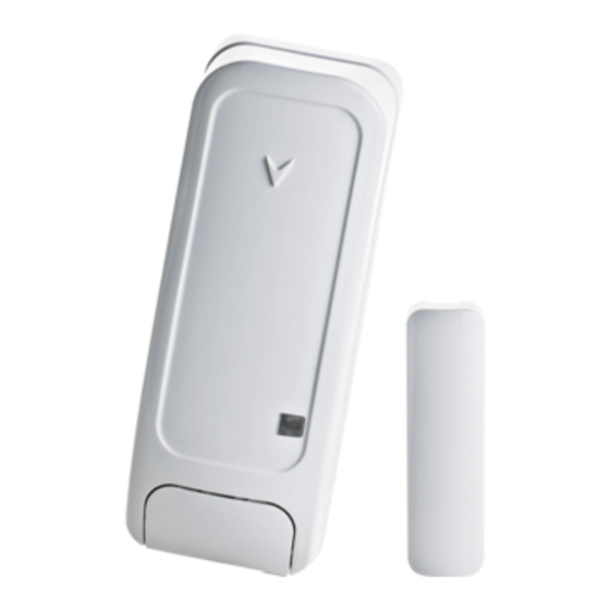
MC-302EL PG2
Two-way Wireless Magnetic Contact Device with
Hard-wired Input
1. INTRODUCTION
The MC-302EL PG2 is a two-way wireless PowerG magnetic contact device that is compatible with
PowerMaster control panels, version X and above. The device includes a built-in reed switch (that
opens upon removal of a magnet placed near it) and an auxiliary hard-wired input, programmable as
either N.O., N.C. or E.O.L., for use with additional sensors – pushbuttons detectors, door contacts,
etc.
The MC-302EL PG2 can be configured through the PowerMaster control panel to allow the installer to
disable the magnet-operated reed switch if only the auxiliary input is needed. The reed switch and the
auxiliary input behave as separate transmitters, although they trigger the same RF transmitter. The
MC-302EL PG2 sends the parameters of the specific alarm to the control panel using PowerG two-
way communications protocol.
The MC-302EL PG2 tamper switch is activated when the cover is removed.
A periodic supervision message is transmitted automatically. The control panel is thus informed, at
regular intervals, of the unit's active participation in the system.
An LED lights whenever alarm or tamper events are reported. The LED does not light while a
supervision message is being transmitted.
Operating power is obtained from an on-board 3 V Lithium battery. When the battery voltage is low, a
"low battery" message is sent to the receiver.
2. INSTALLATION
2.1 Mounting
(Fig. 3a and 3b)
It is highly recommended to attach the transmitter to the top of the door/window on the fixed frame and the magnet to the movable part
(door or window). Make sure that the magnet is located not more than 6 mm (0.25 in.) from the transmitter's marked side.
Note: Once the cover is removed, a tamper message is transmitted to the receiver. Subsequent removal of the battery prevents
transmission of "TAMPER RESTORE", leaving the receiver in permanent alert. To avoid this, press the tamper switch while you remove
the battery.
Caution!
Risk of explosion if battery is replaced by an incorrect type. Dispose of used battery according to manufacturer's instructions.
Attention! The unit has a back tamper switch (optional) under the PCB. As long as the PCB is seated firmly within the base, the switch
lever will be pressed against a special break-away base segment that is loosely connected to the base (Figures 2 and 3a). Be sure to
fasten the break-away segment to the wall. If the detector unit is forcibly removed from the wall, this segment will break away from the
base, causing the tamper switch to open
B
A
F
E
A. Flexible Retainer
B. Break-away base segment (for Back Tamper)
C. P.C. board edge supports
D. Mounting holes
E. Wiring inlet
F. Plastic standoff for case closure screw
Figure 2. Base with P.C. Board Removed
D-304537 MC-302EL PG2 Installation Instructions
.
D
Installation Instructions
C
Note: 868 MHz device is illustrated in the above example. The
same mounting procedure should be performed for 433 MHz and
915 MHz devices.
* This screw is used for back tamper only.
A. Transmission LED
B. Magnet
Figure 1: External View
Figure 3a. Mounting
1
Advertisement
Table of Contents

Related Manuals for Tyco Visonic MC-302EL PG2


Summary of Contents for Tyco Visonic MC-302EL PG2
- Page 1 MC-302EL PG2 Two-way Wireless Magnetic Contact Device with Installation Instructions Hard-wired Input 1. INTRODUCTION The MC-302EL PG2 is a two-way wireless PowerG magnetic contact device that is compatible with PowerMaster control panels, version X and above. The device includes a built-in reed switch (that opens upon removal of a magnet placed near it) and an auxiliary hard-wired input, programmable as either N.O., N.C.
- Page 2 1. Insert a flat-edged screwdriver into WARNING! To comply with FCC and IC RF exposure the slot and push upward to compliance requirements, the magnet contact device should be remove cover. located in a distance of at least 20 cm from all persons during 2.
- Page 3 3. LOCAL DIAGNOSTICS TEST Before testing, separate the base from the cover (see Fig. 3a). A. Press the tamper switch once and release it. B. Put back the cover to return the tamper switch to its normal (undisturbed) position, and then secure the front cover to the base with the case closure screw.
- Page 4 EN 50131-1 Security Grade According to EN 50131-1:2006 and A1:2009, this equipment can be applied in installed systems up to and including Security Grade 2. EN 50131-1 Environmental Class II Class FCC Compliance Statement The digital circuitry of this device has been tested and found to comply with the limits for a Class B digital device, pursuant to Part 15 of the FCC Rules.
- Page 5 EMAIL: info@visonic.com INTERNET: www.visonic.com VISONIC LTD. 2013 D-304537 MC-302EL PG2 (Rev 0, 01/13) D-304537 MC-302EL PG2 Installation Instructions...
Need help?
Do you have a question about the Visonic MC-302EL PG2 and is the answer not in the manual?
Questions and answers