Table of Contents
Advertisement
Quick Links
To download the full user manual and register your product, please visit:
www.
.com/m/29009879 or scan the QR code to the right.
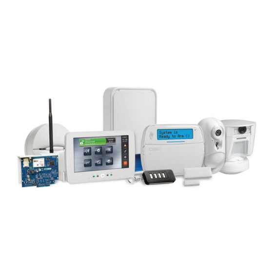
DSC
HS2016/HS2016-4/HS2032/HS2064/HS2064 E/
HS2128/HS128 E Alarm Panel
User Guide
WARNING: This manual contains information on limitations regarding product use and function and
information on the limitations as to liability of the manufacturer. The entire manual should be care-
fully read.
firealarmresources.com
Advertisement
Table of Contents

Related Manuals for Tyco DSC neo HS2016


Summary of Contents for Tyco DSC neo HS2016
- Page 1 To download the full user manual and register your product, please visit: www. .com/m/29009879 or scan the QR code to the right. HS2016/HS2016-4/HS2032/HS2064/HS2064 E/ HS2128/HS128 E Alarm Panel User Guide WARNING: This manual contains information on limitations regarding product use and function and information on the limitations as to liability of the manufacturer. The entire manual should be care- fully read. firealarmresources.com...
-
Page 2: Table Of Contents
Table of Contents 1.0 Quick Reference 2.0 Understanding Your Keypad 2.1 Icon and LED Keypad Symbols 2.2 Keypad Models 3.0 The PowerSeries Neo Security System 3.1 General System Operation 3.2 Testing Your System 3.3 Monitoring 3.4 Maintenance 4.0 Setting the Alarm System 4.1 Alarm System Setting Methods 4.2 Setting the System (Infinite Exit Delay) 4.3 Away Setting the System with the Keypad 4.4 Exit Delay Time Restart 4.5 Alarm Cancel Window... -
Page 3: Quick Reference
Chapter 1.0 Quick Reference 1.0 Quick Reference The PowerSeries Neo Alarm System uses shortcut keys to access features on all models of keypads. When using an LCD keypad, the PowerSeries Neo Alarm System uses a menu based nav- igation system. The scroll keys can be used to navigate through the list of options contained within the current menu. - Page 4 Chapter 1.0 Quick Reference Action Press Add/Delete User [*][5] + [Master Code] + [Access Code] + 1 Reset Smoke Detectors OR [*][7][2] View Troubles [*][2] + [Access Code*] + View Alarms [*][3] + [Access Code*] + Perform System Test [*][6] + [Master Code] + [0][4] + Buzzer Volume [*][6] + [Master Code] + [1][4] + - 4 -...
-
Page 5: Understanding Your Keypad
Chapter 2.0 Understanding Your Keypad 2.0 Understanding Your Keypad The PowerSeries Neo Alarm System supports a variety of wireless, hardwired and proximity sensor LCD, LED and Icon keypads. All keypads come equipped with the LED status lights described in section 1 "Quick Reference". HS2LCD series keypads display system messages on their LCD screen. -
Page 6: Keypad Models
Chapter 2.0 Understanding Your Keypad OPEN This icon is used with clock digits 1 and 2 to indicate activated zones (not alarm) on the system. When zones are opened, the OPEN icon will turn on, clock digits 1 and 2 will scroll through the violated zones. -
Page 7: The Powerseries Neo Security System
Chapter 3.0 The PowerSeries Neo Security System 3.0 The PowerSeries Neo Security System Your PowerSeries Neo has been designed to provide you with the greatest possible flexibility and convenience. Read this manual carefully and have your installer instruct you on how to operate your system and which features have been implemented in your system. -
Page 8: Maintenance
Chapter 3.0 The PowerSeries Neo Security System Note: Ensure that your installer verifies that your system is compatible with the Central Station Receiver format at yearly intervals. 3.4 Maintenance With normal use, the system requires minimum maintenance. Note the following points: Do not wash the security equipment with a wet cloth. -
Page 9: Setting The Alarm System
Chapter 4.0 Setting the Alarm System 4.0 Setting the Alarm System 4.1 Alarm System Setting Methods The PowerSeries Neo system is capable of completing the full alarm system setting procedure using one of the following methods: push button switch mounted outside the supervised premises; or protective switch (i.e., door contact) fitted to the final exit door of the alarmed premises or area. -
Page 10: Exit Delay Time Restart
Chapter 4.0 Setting the Alarm System After successfully initiating the setting sequence the: Exit Delay in Progress indicator turns on. Ready indicator remains lit. Exit Delay timer begins counting down. Keypad beeps six times, continues beeping once per second until beeping rapidly in the final ten seconds. The system may be configured to have a persistent exit delay that only ends when the exit door is opened and closed, or when a button is pressed outside the protected... -
Page 11: Arming The System With A 2-Way Wireless Key
Chapter 4.0 Setting the Alarm System Away Set Away Set Stay Set Stay Set Unset Unset Panic Panic Command Output 1 Command Output 1 Message LED Status LEDs Note: Panic feature has not been evaluated by UL. All wireless key buttons are programmable. Verify the functions assigned to each key with your installer. -
Page 12: Engineer Reset
Chapter 4.0 Setting the Alarm System Present your proximity tag to a keypad equipped with a proximity sensor anytime the system is set. ( Set indicator is on). If you walk through the entry door the keypad will beep. Present your proximity tag within _____ seconds to avoid an alarm condition. -
Page 13: Emergency Keys
Chapter 5.0 Emergency Keys 5.0 Emergency Keys IMPORTANT: EMERGENCY USE ONLY! Pressing both the emergency keys generates a Fire, Medical, or Panic Alarm, and alerts the mon- itoring station. e.g., to generate a medical alarm press both of the medical alarm keys for 2 seconds and the display on an LCD keypad will show Hold down keys for Med. -
Page 14: Access Code Types
Chapter 6.0 Access Code Types 6.0 Access Code Types The alarm system provides the following user access code types: Code Add User Delete Set Unset Access User Func- Installer User Codes tions Master Yes Yes User Yes Yes Supervisor All but All but Yes Yes Master... -
Page 15: Opening The Access Code Menu
Chapter 6.0 Access Code Types 6.1 Opening the Access Code Menu To add, change or delete Access Codes first open the Access Code Menu: LCD Display Press [*][5] or press [*] and use the scroll keys to navigate to Press (*) for <> Access Codes and press [*]. -
Page 16: Swinger Shutdown
Chapter 6.0 Access Code Types 6.4 Swinger Shutdown The Control Panel has a swinger shutdown feature that when enabled a programmable number of trips shall shut down the zone. Note: Must be enabled and configured by installer. 6.5 Call Waiting The Control Panel includes a programmable option for call waiting to prevent a call waiting line from interfering with the alarm verification process. - Page 17 Chapter 6.0 Access Code Types Word Library Text Text Text Text Text Text Aborted 041 Communicator 081 Front 121 Memory 161 Screen 201 7 042 Computer 082 Furnace 122 Menu 162 Second 202 8 Access 043 Control 083 Gallery 123 Monoxide 163 Sensor 203 9 Active 044 Date...
-
Page 18: Trouble Conditions
Chapter 7.0 Trouble Conditions 7.0 Trouble Conditions Occasionally, you may have a problem with your Alarm Controller or telephone line. If this hap- pens, your Alarm Controller identifies the problem and displays an error message. Refer to the provided list when you see an error message on the display. If additional help is required, contact your distributor for service. - Page 19 Chapter 7.0 Trouble Conditions Trouble Trouble Trouble Trouble Trouble Description Notification Condition Types Level 2 Level 1 Level 3 Battery Trouble 02 The system has detected a bat- Low Battery tery trouble condition. Call (System for service. Label) No Battery service (Sys- tem Label) High Current...
- Page 20 Chapter 7.0 Trouble Conditions Trouble Trouble Trouble Trouble Trouble Description Notification Condition Types Level 2 Level 1 Level 3 Device Faults The system has detected an issue with one or more con- Heat nected devices. Call for ser- ...
- Page 21 Chapter 7.0 Trouble Conditions Trouble Trouble Trouble Trouble Trouble Description Notification Condition Types Level 2 Level 1 Level 3 Module Super- The system has detected a HSM2HOST 01 vision supervisory trouble condition Keypad Keypad 1-16 with one or more modules on Zone Zone the system.
- Page 22 Chapter 7.0 Trouble Conditions Trouble Trouble Trouble Trouble Trouble Description Notification Condition Types Level 2 Level 1 Level 3 Not Networked 12 The system has detected a net- Zone Zone label work trouble condition with 001-128 one or more modules on the Keypad Keypad 1-16 system.
-
Page 23: Safety Instructions
Chapter 8.0 Safety Instructions 8.0 Safety Instructions This equipment is stationary-fixed and must be installed by Service Persons only (Service Person is defined as a person having the appropriate technical training and experience necessary to be aware of hazards to which that person may be exposed in performing a task and of measures to minimize the risks to that person or other persons). - Page 24 Chapter 8.0 Safety Instructions This publication covers the following models: HS2016 HS2128 HS2LCDRF HS2LED HS2016-4 HS2128 E HS2ICN HS2LCDRFP HS2032 HS2TCHP HS2LCDWF8 HS2ICNP HS2064 HS2LCD HS2LCDWFP8 HS2ICNRF8 HS2064 E HS2LCDP HS2LCDWFPV8 HS2ICNRFP8 - 24 - firealarmresources.com...
-
Page 25: Reference Sheets
Chapter 9.0 Reference Sheets 9.0 Reference Sheets Fill out the following information for future reference and store this guide in a safe place. 9.1 System Information Mark if Buttons are Enabled [F] FIRE [M] Medical [P] PANIC The Exit Delay Time is _______ seconds. The Entry Delay Time is _______ seconds. -
Page 26: Access Code And Sensor/Zone Information
Chapter 10.0 Access Code and Sensor/Zone information 10.0 Access Code and Sensor/Zone information Master Code [01] : _________________________ Access Code Reference Sheet Code Access Code Code Access Code Code Access Code Code Access Code ... - Page 27 Chapter 10.0 Access Code and Sensor/Zone information Sensor/Zone Information Sensor Protected Area Sensor Type Sensor Protected Area Sensor Type ...
- Page 28 Chapter 10.0 Access Code and Sensor/Zone information Sensor Protected Area Sensor Type Sensor Protected Area Sensor Type ...
-
Page 29: Locating Detectors And Escape Plan
Chapter 11.0 Locating Detectors and Escape Plan 11.0 Locating Detectors and Escape Plan The following information is for general guidance only and it is recommended that local fire codes and regulations be consulted when locating and installing smoke and CO alarms. 11.1 Smoke Detectors Research has shown that all hostile fires in homes generate smoke to a greater or lesser extent. -
Page 30: Fire Escape Planning
Chapter 11.0 Locating Detectors and Escape Plan Figure 3a Figure 4 11.2 Fire Escape Planning There is often very little time between the detection of a fire and the time it becomes deadly. It is thus very important that a family escape plan be developed and rehearsed. Every family member should participate in developing the escape plan. -
Page 31: Carbon Monoxide Detectors
Chapter 11.0 Locating Detectors and Escape Plan Figure 5 11.3 Carbon Monoxide Detectors Carbon monoxide is colorless, odorless, tasteless, and very toxic, it also moves freely in the air. CO detectors can measure the concentration and sound a loud alarm before a potentially harmful level is reached. -
Page 32: Regulatory Statements
SIMPLIFIED EU DECLARATION OF CONFORMITY Hereby, Tyco Safety Products Canada Ltd declares that the radio equipment type is in compliance with Directive 2014/53/EU. The full text of the EU declarations of conformity for the models men- tioned below are available at the following internet addresses: HS2LCDRF(P)(V)4: http://dsc.com/pdf/1401057... - Page 33 Chapter 12.0 Regulatory Statements of the two methods mentioned above. Please check with the Installer which method has been enabled for your system. Unsetting Methods The HS2128/HS2064/HS2032/HS2016 is capable to support the following unsetting methods in accordance with BS8243: 6.4.2 Prevention of entry to the supervised premises before the alarm system is unset. Unsetting using remote keyfob (PG8929, PG8939, PG8949) before entering the supervised premises causes or permits the initial entry door to be unlocked.
-
Page 34: Installer Warning
Chapter 13.0 Installer Warning hazards such as smoking in bed, violent explosions, escaping gas, improper stor- 13.0 Installer Warning age of flammable materials, overloaded electrical circuits, children playing with matches or arson. Even if the smoke detector operates as intended, there may be circumstances Warning Please Read Carefully when there is insufficient warning to allow all occupants to escape in time to Note To Installers:... -
Page 35: Eula
(the company, individual or entity who acquired the Software and any related problems caused by changes in the operating characteristics of the HARDWARE, Hardware) and Digital Security Controls, a division of Tyco Safety Products or for problems in the interaction of the SOFTWARE PRODUCT with non-DSC- Canada Ltd. - Page 36 The trademarks, logos, and service marks displayed on this document are registered in the United States [or other countries]. Any misuse of the trademarks is strictly prohibited and Tyco Security Products will aggress- ively enforce its intellectual property rights to the fullest extent of the law, including pursuit of criminal pro- secution wherever necessary.
Need help?
Do you have a question about the DSC neo HS2016 and is the answer not in the manual?
Questions and answers