Table of Contents
Advertisement
Quick Links
Evaluating the LTC9101-2A/LTC9101-2 and LTC9102 48-Channel IEEE 802.3at/bt PSE
GENERAL DESCRIPTION
The EVAL-LTC9101-2 is a 48-channel IEEE 802.3at/bt compli-
ant power sourcing equipment (PSE). The EVAL-LTC9101-2
KIT includes the DC3159A-D or DC3159A-C daughter card,
the DC3017A-B motherboard, and features the LTC9101-2A/
LTC9101-2
and
LTC9102
chipset.
In the EVAL-LTC9101-2 KIT, the daughter card has a single
LTC9101-2A
or
LTC9101-2
digital controller. The DC3159A-D
daughter card has the
LTC9101-2A
LTC9101-2. The digital controller interfaces with four
(12-channel) analog controllers for a total of 48 PSE channels.
The
LTC9101-2A/LTC9101-2
face allowing the
LTC9101-2
2
ler I
C interface and eliminating the need for costly optocouplers
and an additional 3.3 V supply.
The EVAL-LTC9101-2A Kit connects to up to forty-eight, 802.3af/at
PDs with an Ethernet splitter for each two ports for 2-pair power
evaluation. This kit version requires host control over I
PLEASE SEE THE LAST PAGE FOR AN IMPORTANT
WARNING AND LEGAL TERMS AND CONDITIONS.
and the DC3159A-C has the
LTC9102
use a proprietary isolated data inter-
to directly connect to the host control-
2
C.
User Guide | EVAL-LTC9101-2
The EVAL-LTC9101-2 Kit connects to up to twenty-four,
802.3af/at/bt PDs directly at each port for 4-pair power evaluation.
This kit version can operate autonomously or with host control over
2
I
C.
Indicator LEDs quickly show channel status for the 48 power
channels. An optional on-board buck regulator provides 3.3 V from
the V
supply for the digital circuity. This demonstration manual
EE
provides an EVAL-LTC9101-2 KIT overview and quick start proce-
dure.
Design files for this circuit board are available at
https://www.analog.com/EVAL-LTC9101-2-KIT
All registered trademarks and trademarks are the property of their respective owners.
UG-2131
Rev. 0 | 1 of 10
Advertisement
Table of Contents

Related Manuals for Analog Devices EVAL-LTC9101-2


Summary of Contents for Analog Devices EVAL-LTC9101-2
-
Page 1: General Description
An optional on-board buck regulator provides 3.3 V from LTC9101-2 LTC9102 chipset. the V supply for the digital circuity. This demonstration manual In the EVAL-LTC9101-2 KIT, the daughter card has a single provides an EVAL-LTC9101-2 KIT overview and quick start proce- LTC9101-2A LTC9101-2 digital controller. The DC3159A-D dure. -
Page 2: Table Of Contents
User Guide EVAL-LTC9101-2 TABLE OF CONTENTS General Description..........1 Isolation.............. 8 EVAL-LTC9101-2 Evaluation Board Photo.... 3 PWRMD Settings..........8 Quick Start Procedure........... 4 Device Configuration.......... 8 EVAL-LTC9101-2-KIT Overview......7 Digital Connections..........8 Port Output............7 OSS and RESET Push Buttons......8 Daughter Card Insertion Precautions.... -
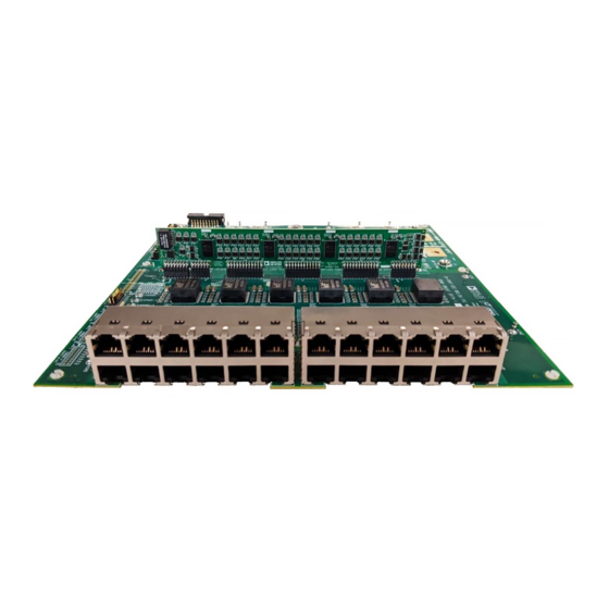
Page 3: Eval-Ltc9101-2 Evaluation Board Photo
User Guide EVAL-LTC9101-2 EVAL-LTC9101-2 EVALUATION BOARD PHOTO Figure 1. EVAL-LTC9101-2 Evaluation Board Photo Table 1. EVAL-LTC9101-2-KIT Options Demo Kit IEEE Standard Daughter Card Mother Board LTC9101 Version 2-Pair Ports 4-Pair Ports EVAL-LTC9101-2A 802.3at DC3159A-D DC3017A-B EVAL-LTC9101-2 802.3bt DC3159A-C DC3017A-B analog.com... -
Page 4: Quick Start Procedure
OPEN DISABLED NOTE: Step 1 only applies to the EVAL-LTC9101-2. 24.3k RESERVED 1. For autonomous operation with the EVAL-LTC9101-2, set the 18.7k RESERVED jumper PWRMD-1 (JP1) on the DC3017A-B motherboard to 14.3k Class 4: 25.5W PM3 through PM7. - Page 5 User Guide EVAL-LTC9101-2 QUICK START PROCEDURE Figure 2. Default Settings for DC3017A-B Motherboard, Jumpers PWRMD0, AD1, CFG0, and CFG1; Switches: AD2 and AD3; Resistor options for AD4 Figure 3. Inserting the DC3159A Daughter Card into J1 through J6 of the DC3017A-B Motherboard analog.com...
- Page 6 User Guide EVAL-LTC9101-2 QUICK START PROCEDURE Figure 4. EVAL-LTC9101-2-KIT Connections analog.com Rev. 0 | 6 of 10...
-
Page 7: Eval-Ltc9101-2-Kit Overview
User Guide EVAL-LTC9101-2 EVAL-LTC9101-2-KIT OVERVIEW The EVAL-LTC9101-2-KIT includes the DC3017A-B, a 24-Port, The EVAL-LTC9101-2 supports 24, 4-pair ports. See Figure 6 4-pair IEEE 802.3at/bt PoE PSE motherboard for a PSE endpoint. the port output map of the EVAL-LTC9101-2. This motherboard accepts either the DC3159A-C or DC3159A-D DAUGHTER CARD INSERTION PRECAUTIONS daughter card with up to forty-eight power channels. -
Page 8: Main Vee Poe Supply
User Guide EVAL-LTC9101-2 EVAL-LTC9101-2-KIT OVERVIEW MAIN V POE SUPPLY The V supply is the main PoE supply connected to the DC3017A motherboard. See the Quick Start Procedure for proper connection Table 4 for appropriate supply voltage ranges. Choose a power supply with a current limit set higher than the maximum allowed output power at each port. -
Page 9: On Board 3.3 V Supply
EVAL-LTC9101-2A (pairs 4, 5 and 7, 8) to Alternative B for the SURGE TESTING second PD. The odd port is Alternative A, while the even port is The EVAL-LTC9101-2-KIT can be configured with either the Digital Alternative B. domain connected to reference ground plane, or with the Digital... - Page 10 Evaluation Board until you have read and agreed to the Agreement. Your use of the Evaluation Board shall signify your acceptance of the Agreement. This Agreement is made by and between you (“Customer”) and Analog Devices, Inc. (“ADI”), with its principal place of business at Subject to the terms and conditions of the Agreement, ADI hereby grants to Customer a free, limited, personal, temporary, non-exclusive, non-sublicensable, non-transferable license to use the Evaluation Board FOR EVALUATION PURPOSES ONLY.
Need help?
Do you have a question about the EVAL-LTC9101-2 and is the answer not in the manual?
Questions and answers