Table of Contents
Advertisement
Quick Links
DESCRIPTION
Evaluation circuit EVAL-LT8350-AZ is a 40V synchronous
buck-boost converter featuring the
up to 2.5A load at 12V output when V
and 40V and will run down to 3V
put current. EVAL-LT8350-AZ runs at 350kHz switching
frequency with spread spectrum frequency modulation
(SSFM) disabled. When enabled, SSFM spreads the
switching frequency of the LT8350 from f
25% for reduced EMI emission.
The LT8350 has an operating input voltage range of
3V to 40V. It has internal, synchronous 42V MOSFETs
at buck-side and 20V MOSFETs at boost-side for high
efficiency and small size. It has an adjustable switching
frequency between 200kHz and 2MHz. The LT8350 can
be synchronized to an external source, programmed with
SSFM enabled for low EMI, or set to normal operation.
The LT8350's integrated LOADTG high side PMOS driver
assists with disconnecting load when a fault is triggered.
LOADTG turns off the PMOS when FB < 0.25V or FB >
1.1V or ISP–ISN > 0.75V. LOADEN can be used directly
to turn off LOADTG and all power switches.
The LT8350 can regulate output current using ISP and
ISN. Maximum load current can be limited when LT8350
is used for a constant voltage regulator. It can be also used
for a LED driver or a battery charger where constant cur-
rent regulation is required. Output current can be adjusted
by placing a controllable DC voltage on the CTRL pin.
40V
LT
8350. It drives
®
is between 9V
IN
with reduced out-
IN
to f
+
SW
SW
DEMO MANUAL
, 18V
, 6A Synchronous
IN
OUT
Buck-Boost Silent Switcher
The output current can be monitored through the ISMON
output pin. ISMON can be used to improve load transient
response by injecting load current to V
injection is described in the following sections.
Undervoltage lockout can be adjusted on EVAL-LT8350-AZ
with a few simple resistor choices.
Small ceramic input and output capacitors are used to
save space and cost. The board is designed with tiny, high
frequency capacitors placed near the V
for a reduction in radiated EMI.
There is an inductor EMI filter and a small ferrite bead EMI
filter on the input and output of EVAL-LT8350-AZ. These
filters, combined with proper board layout and SSFM,
are effective in reducing EMI to pass CISPR25 class 5
conducted EMI. Please follow the recommended layout
and four-layer PCB thickness of EVAL-LT8350-AZ for low
EMI applications.
The LT8350 data sheet gives a complete description of
the part, operation, and applications information. The data
sheet must be read in conjunction with this demo manual
for EVAL-LT8350-AZ. The LT8350RV is assembled in a
32-lead laminate package with QFN footprint (LQFN) with
thermally enhanced exposed ground pads. Proper board
layout is essential for maximum thermal performance.
Design files for this circuit board are
All registered trademarks and trademarks are the property of their respective owners.
EVAL-LT8350-AZ
LT8350
. The load current
C
and V
IN
OUT
available.
®
pins
Rev. 0
1
Advertisement
Table of Contents

Related Manuals for Analog Devices EVAL-LT8350-AZ


Summary of Contents for Analog Devices EVAL-LT8350-AZ
- Page 1 There is an inductor EMI filter and a small ferrite bead EMI at buck-side and 20V MOSFETs at boost-side for high filter on the input and output of EVAL-LT8350-AZ. These efficiency and small size. It has an adjustable switching filters, combined with proper board layout and SSFM, frequency between 200kHz and 2MHz.
-
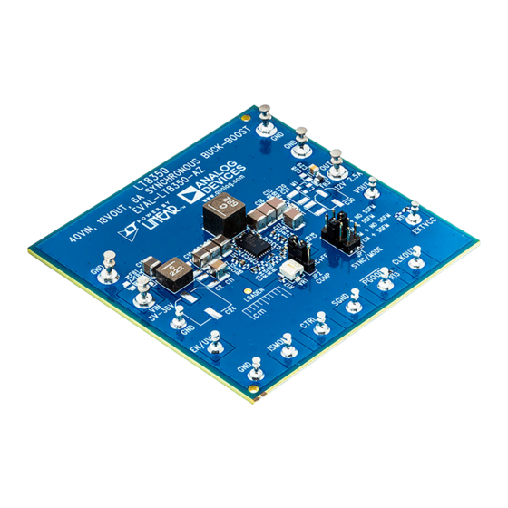
Page 2: Board Photo
DEMO MANUAL EVAL-LT8350-AZ BOARD PHOTO PERFORMANCE SUMMARY Specifications are at T = 25°C PARAMETER CONDITIONS UNITS Input Voltage V Range Operating, R7 = 402k, R12 = OPEN Full Load (2.5A) Input Voltage Range Component Temperature < 85°C at Room Temperature with No Airflow Output Voltage (V R22 = 110k, R3 = 10.0k... -
Page 3: Quick Start Procedure
QUICK START PROCEDURE 4. Set JP2 at RC for typical loop compensation, at RC+FF Evaluation circuit EVAL-LT8350-AZ is easy to set up to for load current injection scheme which improves load evaluate the performance of the LT8350. Refer to Figure 1 transient response. -
Page 4: Test Results
WITHOUT EMI FILTERS WITH EMI FILTERS INPUT VOLTAGE (V) EVAL-8350 F03 1µs/DIV EVAL-8350 F02 Figure 2. EVAL-LT8350-AZ Efficiency vs Input Voltage for Figure 3. EVAL-LT8350-AZ Output Voltage Ripple at 12V 2.5A Load with SSFM Input Voltage and 2.5A Load 500mV/DIV 500mV/DIV AC-COUPLED... - Page 5 LOAD CURRENT INJECTION FOR FASTER LOAD TRANSIENT RESPONSE Load transient response can be improved with JP2 = As EVAL-LT8350-AZ uses R1 = 10mΩ and R17 = 3.01kΩ, RC+FF , which is called load current injection. The idea is VR1 is determined to 1.2kΩ. Figure 8 and Figure 9 show...
- Page 6 FREQUENCY (MHz) EVAL-8350 F10a EVAL-8350 F10b (a) CISPR25 Average, Voltage Method (b) CISPR25 Peak, Voltage Method Figure 10. EVAL-LT8350-AZ CISPR25 Voltage Conducted EMI Performance with 12V to 12V at 2.5A, JP1 = DCM+SSFM CLASS 5 AVERAGE LIMIT CLASS 5 PEAK LIMIT...
-
Page 7: Parts List
ITEM QTY REFERENCE PART DESCRIPTION MANUFACTURER/PART NUMBER Required Electrical Components IC, BUCK-BOOST VOLTAGE REGULATOR, LQFN-32 ANALOG DEVICES, LT8350RV#PBF IND., 6.8μH, PWR, SHIELDED, 20%, 9A, 20.80mΩ, 6.56mm × COILCRAFT, XAL6060-682MEB 6.36mm, AEC-Q200, XAL6060 CAP ., 4.7μF, X5R, 10V, 20%, 0402, AEC-Q200... - Page 8 DEMO MANUAL EVAL-LT8350-AZ PARTS LIST ITEM QTY REFERENCE PART DESCRIPTION MANUFACTURER/PART NUMBER XSTR., OPTION, MOSFET, P-CH, SOT-23 C15, C18, C25 CAP ., OPTION, 0402 CAP ., 68μF, ALUM POLY, 50V, 20%, SMD, 8.0mm × 10.0mm NICHICON, GYA1H680MCQ1GS CAP ., 47μF, ALUM POLY, 16V, 20%, SMD, 5.0mm × 5.8mm,...
-
Page 9: Schematic Diagram
Devices for its use, nor for any infringements of patents or other rights of third parties that may result from its use. Specifications subject to change without notice. No license is granted by implication or otherwise under any patent or patent rights of Analog Devices. - Page 10 Board until you have read and agreed to the Agreement. Your use of the Evaluation Board shall signify your acceptance of the Agreement. This Agreement is made by and between you (“Customer”) and Analog Devices, Inc. (“ADI”), with its principal place of business at One Technology Way, Norwood, MA 02062, USA. Subject to the terms and conditions of the Agreement, ADI hereby grants to Customer a free, limited, personal, temporary, non-exclusive, non-sublicensable, non-transferable license to use the Evaluation Board FOR EVALUATION PURPOSES ONLY.
Need help?
Do you have a question about the EVAL-LT8350-AZ and is the answer not in the manual?
Questions and answers