Table of Contents
Advertisement
Quick Links
Evaluating the LTC9101-3/LTC9103 16-Port, IEEE 802.3at PSE Controller with Power Management and LED Control
FEATURES
16 Port IEEE 802.3at-compliant PSE
►
Autonomous Power Management with flash configuration
►
Serial LED driver for Port LEDs
►
EVALUATION KIT CONTENTS
EVAL-LTC9101-3-AZ Daughter Card
►
EVAL-LTC9101-3-MB-AZ Motherboard
►
DOCUMENTS NEEDED
LTC9101-3/LTC9103 Datasheet
ADDITIONAL HARDWARE NEEDED
DC Power Supply
►
IEEE 802.3af/at Powered Device(s)
►
SOFTWARE NEEDED
Contact Analog Devices Applications for information regarding Cus-
tom Configurations.
GENERAL DESCRIPTION
The EVAL-LTC9101-3 is a 16-channel IEEE 802.3at compliant pow-
er sourcing equipment (PSE) with autonomous power management
and serial LED driver for port LEDs. The EVAL-LTC9101-3 includes
the EVAL-LTC9101-3-AZ daughter card, the EVAL-LTC9101-3-MB-
AZ motherboard, and features the
platform chipset.
In the EVAL-LTC9101-3, a single
faces with up to two LTC9103, 8-channel, analog controllers for
16 power channels total. Up to sixteen IEEE 802.3af/at/bt powered
devices (PDs) can be connected to the EVAL-LTC9101-3 and
powered from this system using a single power supply.
PLEASE SEE THE LAST PAGE FOR AN IMPORTANT
WARNING AND LEGAL TERMS AND CONDITIONS.
LTC9101-3
and
LTC9103
PSE
LTC9101-3
digital controller inter-
User Guide | EVAL-LTC9101-3
The
LTC9101-3
and
LTC9103
terface allowing the
LTC9101-3
as the host controller and eliminate the need for an additional
isolated 3.3 V supply. The EVAL-LTC9101-3 operates completely
autonomously without a host controller, including flash configuration
for power management and port LEDs. Port Status and Fault LEDs
quickly show PoE status for up to sixteen ports, including fault
codes, driven by the LTC9101-3 using a serial LED driver. A Supply
Overload LED warns if system power usage is near the power
budget and indicates if port power is denied or revoked.
Robust surge protection is provided by design and on-board
surge protection devices. An optional on-board buck regulator
provides 3.3 V from the VEE supply for the digital circuits. This
demonstration manual provides a quick start procedure and an
EVAL-LTC9101-3 overview.
Design files for this circuit board are available at
log.com/EVAL-LTC9101-3
All registered trademarks and trademarks are the property of their respective owners.
UG-2132
use a proprietary isolated data in-
to share the same logic supply
https://www.ana-
Rev. 0 | 1 of 10
Advertisement
Table of Contents

Related Manuals for Analog Devices EVAL-LTC9101-3


Summary of Contents for Analog Devices EVAL-LTC9101-3
-
Page 1: Features
GENERAL DESCRIPTION The EVAL-LTC9101-3 is a 16-channel IEEE 802.3at compliant pow- er sourcing equipment (PSE) with autonomous power management and serial LED driver for port LEDs. The EVAL-LTC9101-3 includes the EVAL-LTC9101-3-AZ daughter card, the EVAL-LTC9101-3-MB- AZ motherboard, and features the... -
Page 2: Table Of Contents
Additional Hardware Needed.........1 Device Configuration.......... 8 Software Needed...........1 Custom Configurations........8 General Description..........1 Digital Connections..........8 EVAL-LTC9101-3 Evaluation Board Photo.... 3 RESET Pushbutton..........8 Quick Start Procedure........... 4 Onboard 3.3 V Supply........8 LTC9101-3 Evaluation Kit........6 Surge Testing............. 8 Port Output............6 Legacy Mode............8... -
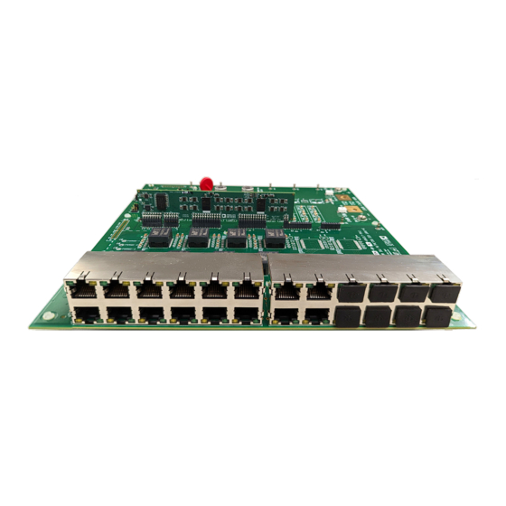
Page 3: Eval-Ltc9101-3 Evaluation Board Photo
User Guide EVAL-LTC9101-3 EVAL-LTC9101-3 EVALUATION BOARD PHOTO Figure 1. EVAL-LTC9101-3 Evaluation Board Photo analog.com Rev. 0 | 3 of 10... -
Page 4: Quick Start Procedure
EVAL-LTC9101-3-MB-AZ motherboard in the EVAL-LTC9101-3. See the section on Port Output for more information. Figure 2. Inserting the EVAL-LTC9101-3-AZ Daughter Card into J1 through J5 of the EVAL-LTC9101-3-MB-AZ Motherboard analog.com Rev. 0 | 4 of 10... - Page 5 User Guide EVAL-LTC9101-3 QUICK START PROCEDURE Figure 3. EVAL-LTC9101-3 Connections analog.com Rev. 0 | 5 of 10...
-
Page 6: Ltc9101-3 Evaluation Kit
PSE, with An IEEE 802.3at PSE uses a single power channel per port, con- port LEDs and test points. nected to either Alternative A or Alternative B. EVAL-LTC9101-3- MB-AZ layout supports up to twenty four 4-pair ports with options PORT OUTPUT for connecting Alternative A and Alternative B. -
Page 7: Daughter Card Insertion Precautions
AGND and DGND for high voltage capacitance discharge. Figure 5 for diagram of connections between Analog and Dig- ital domains, as well as chassis ground on the EVAL-LTC9101-3- MB-AZ motherboard. The EVAL-LTC9101-3-AZ daughter card is laid out with isolation. -
Page 8: Device Configuration
Class Invalid Blink Inrush Fault Blink The EVAL-LTC9101-3 can be configured with either the Digital domain connected to reference ground plane, or with the Digital do- and I Blink main floating with the Analog domain for different surge test setups. -
Page 9: Power Management
User Guide EVAL-LTC9101-3 LTC9101-3 EVALUATION KIT power management settings. The Supply Overload (OVR) LED POWER MANAGEMENT turns on if it is near the power budget and blink if power is denied LTC9101-3 manages a user-defined system-level power budg- or revoked. The... - Page 10 Evaluation Board until you have read and agreed to the Agreement. Your use of the Evaluation Board shall signify your acceptance of the Agreement. This Agreement is made by and between you (“Customer”) and Analog Devices, Inc. (“ADI”), with its principal place of business at Subject to the terms and conditions of the Agreement, ADI hereby grants to Customer a free, limited, personal, temporary, non-exclusive, non-sublicensable, non-transferable license to use the Evaluation Board FOR EVALUATION PURPOSES ONLY.
Need help?
Do you have a question about the EVAL-LTC9101-3 and is the answer not in the manual?
Questions and answers