Table of Contents
Advertisement
Quick Links
DESCRIPTION
Evaluation board EVAL-LT8376-AZ is a 60V, 2A syn-
chronous Buck LED driver featuring the
LT8376-AZ drives a single string of LEDs up to 36V at
1.5A when V
is between 43V and 57V. EVAL-LT8376-AZ
IN
has an undervoltage lockout (UVLO) set at 40V with 2V
hysteresis for turn-on. EVAL-LT8376-AZ runs at 350kHz
switching frequency and features optional spread spec-
trum modulation (SSFM). With SSFM enabled, LT8376
modulates its switching frequency from f
to reduce EMI emissions.
The LT8376 has an input voltage range of 3.6V to 60V.
LT8376 has internal, synchronous 60V switches for
high efficiency and small size. LT8376 has an adjustable
switching frequency between 200kHz and 2MHz. The
LT8376 can be synchronized with an external clock source
or configured with SSFM enabled for low EMI. EVAL-
LT8376-AZ includes a SYNC/SSFM jumper to configure
the LT8376 for either external frequency synchronization,
SSFM enabled for low EMI, or set to normal operation
with SSFM disabled.
The LT8376's integrated PWMTG high-side PMOS driver
assists with PWM dimming of the connected LEDs. The
LED string can be PWM dimmed for accurate brightness
control with an externally generated PWM signal or an
internally-generated PWM signal. EVAL-LT8376-AZ has
jumpers that can be set to switch between internally-gen-
erated PWM signal, externally generated PWM signal, and
100% on with no PWM signal. The LT8376 can also be
analog dimmed by placing a controllable DC voltage on
the CTRL pin. When running PWM dimming with SSFM
enabled, the SSFM aligns itself with the PWM signal for
flicker-free operation of the LED string. This applies to
both internal and external PWM dimming.
DEMO MANUAL EVAL-LT8376-AZ
Synchronous Step-Down LED Driver
Small ceramic input and output capacitors are used to
LT
8376. EVAL-
save space and cost. The input and output filters on
®
EVAL-LT8376-AZ reduce its EMI. The filters consist of a
small ferrite bead or inductor and high frequency ceramic
capacitors. These filters, combined with proper board
layout and SSFM, are very effective in reducing EMI to
comply with CISPR25 class 5 limits. Please follow the
recommended layout and the four-layer PCB thickness of
to f
+ 25%
EVAL-LT8376-AZ. For best efficiency and PWM dimming
SW
SW
performance, the EMI filters at the input and output can
be removed.
The open LED overvoltage protection (OVP) uses the IC's
constant voltage regulation loop to regulate the output to
approximately 41V if the LED string is opened. The output
current can be monitored through the ISMON pin. Also,
the FAULT pin can be used for open and short detection.
The input undervoltage lockout (UVLO), LED current,
output overvoltage protection (OVP), and switching fre-
quency, can all be easy adjusted with simple modifications
to EVAL-LT8376-AZ.
The LT8376 data sheet gives a complete description of the
device, operation, and applications information. The data
sheet must be read in conjunction with this demo manual
for evaluation board EVAL-LT8376-AZ. The LT8376RV
is assembled in a 28-lead plastic LQFN package with a
thermally enhanced exposed ground pad. Proper board
layout is essential for maximum performance. See the
data sheet section "Designing the Printed Circuit Board".
Design files for this circuit board are
All registered trademarks and trademarks are the property of their respective owners.
60V, 2A Silent Switcher
LT8376
available.
Rev. 0
1
Advertisement
Table of Contents

Subscribe to Our Youtube Channel
Related Manuals for Analog Devices EVAL-LT8376-AZ


Summary of Contents for Analog Devices EVAL-LT8376-AZ
- Page 1 The input and output filters on ® LT8376-AZ drives a single string of LEDs up to 36V at EVAL-LT8376-AZ reduce its EMI. The filters consist of a 1.5A when V is between 43V and 57V. EVAL-LT8376-AZ...
-
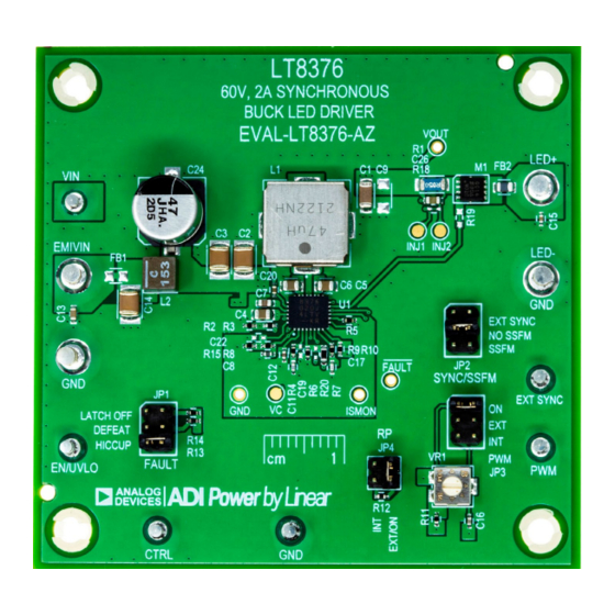
Page 2: Board Photo
DEMO MANUAL EVAL-LT8376-AZ BOARD PHOTO PERFORMANCE SUMMARY Specifications are at T = 25°C PARAMETER CONDITION UNITS Input Voltage EMIVIN Range Operating Switching Frequency (f R5 = 287k, JP2 = NO SSFM Spread Spectrum (SSFM) Range R5 = 287k, JP2 = SSFM R1 = 0.05Ω, R8, R15 = 100k,... -
Page 3: Quick Start Procedure
LT8376-AZ uses a 50mΩ current sense resistor, and a QUICK START PROCEDURE Evaluation board EVAL-LT8376-AZ is easy to set up to 5. Observe the LED string running at the programmed evaluate the performance of the LT8376. Follow the pro- LED current. - Page 4 DEMO MANUAL EVAL-LT8376-AZ QUICK START PROCEDURE Figure 1. Setup Drawing for EVAL-LT8376-AZ Rev. 0...
-
Page 5: Test Results
EVAL-8376 F04 500µs/DIV 10µs/DIV 128:1 PWM RATIO, 192Hz PWM FREQUENCY Figure 3. EVAL-LT8376-AZ Internal PWM Figure 4. EVAL-LT8376-AZ: 50% to 100% to 50% Dimming with EMI Filters: 48V , 36V , 1.5A Load Step Transient Response, 48V Figure 5. EVAL-LT8376-AZ Board Thermal Image: 48V , 36V , 1.5A (SSFM ON) - Page 6 EVAL-8376 F06b EVAL-8376 F06a (b) CISPR25 Average Conducted EMI – Voltage Method (a) CISPR25 Peak Conducted EMI – Voltage Method Figure 6. EVAL-LT8376-AZ Conducted Emissions (Voltage Method): 48V , 36V , 1.5A (SSFM ON) CLASS 5 PEAK LIMIT CLASS 5 AVERAGE LIMIT...
-
Page 7: Parts List
DEMO MANUAL EVAL-LT8376-AZ PARTS LIST ITEM REFERENCE PART DESCRIPTION MANUFACTURER/PART NUMBER Required Circuit Components CAP ., 10μF, X7R, 50V, 10%, 1206 SAMSUNG, CL31B106KBHNNNE C2, C3 CAP ., 4.7μF, X7S, 100V, 10%, 1210 SAMSUNG, CL32Y475KCVZW6E C4-C6 CAP ., 0.47μF, X7R, 100V, 10%, 0805 AVX, 08051C474KAZ2A CAP ., 2.2μF, X7R, 10V, 10%, 0603... - Page 8 DEMO MANUAL EVAL-LT8376-AZ PARTS LIST ITEM REFERENCE PART DESCRIPTION MANUFACTURER/PART NUMBER IND., 15μH, PWD, 20%, 2.9A, 109mΩ, 4mm × 4mm, COILCRAFT, XAL4040-153MEB AEC-Q200 Optional Electrical Components CAP ., 10μF, X7R, 50V, 10%, 1206 SAMSUNG, CL31B106KBHNNNE C19, C22 CAP ., OPTION, 0402 RES., 0Ω, 1/16W, 0402...
-
Page 9: Schematic Diagram
Devices for its use, nor for any infringements of patents or other rights of third parties that may result from its use. Specifications subject to change without notice. No license is granted by implication or otherwise under any patent or patent rights of Analog Devices. - Page 10 Board until you have read and agreed to the Agreement. Your use of the Evaluation Board shall signify your acceptance of the Agreement. This Agreement is made by and between you (“Customer”) and Analog Devices, Inc. (“ADI”), with its principal place of business at One Technology Way, Norwood, MA 02062, USA. Subject to the terms and conditions of the Agreement, ADI hereby grants to Customer a free, limited, personal, temporary, non-exclusive, non-sublicensable, non-transferable license to use the Evaluation Board FOR EVALUATION PURPOSES ONLY.
Need help?
Do you have a question about the EVAL-LT8376-AZ and is the answer not in the manual?
Questions and answers