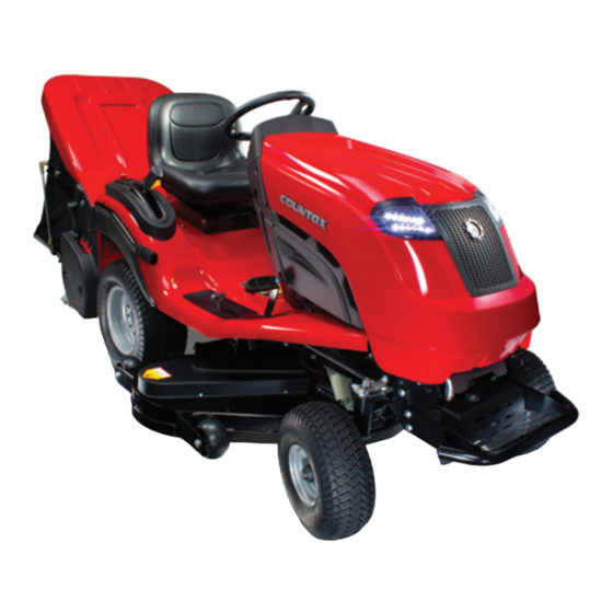
Countax B MK4 Series Operator's Manual

Countax B MK4 Series Operator's Manual

Garden lawn tractor

Advertisement

GARDEN LAWN TRACTOR
Operator Manual
B Series / C Series MK4
Models C50, C60, C80, B60-4WD & B250-4WD
ENGLISH
October 2014 issue
Part No. 366015500 C
The use of fuel that does not meet the following criteria will
void the product warranty.
• Use fuel rated to a minimum of 91 RON.
• Contains a maximum level of 10% ethanol (E10).
• Contains a maximum level of 10% MTBE.
• It is acceptable to use fuel containing up to 5% methanol
by volume, as long as it also contains cosolvents and
corrosion inhibitors to protect the fuel system.

Advertisement

Table of Contents
loading
Need help?

Need help?

Do you have a question about the B MK4 Series and is the answer not in the manual?

Questions and answers

Summary of Contents for Countax B MK4 Series

  • Page 1 GARDEN LAWN TRACTOR Operator Manual B Series / C Series MK4 Models C50, C60, C80, B60-4WD & B250-4WD The use of fuel that does not meet the following criteria will void the product warranty. • Use fuel rated to a minimum of 91 RON. • Contains a maximum level of 10% ethanol (E10).
  • Page 2: Table Of Contents

    Table of Contents Introduction........ 2 - 3 Trouble Shooting......40 - 45 Safety Rules........ 4 - 11 Service Parts....... 46 Control Layouts......12 - 14 Accessory List......47 Dashboard Controls....15 - 20 Specifications......48 Using the Tractor......21 - 24 Personal Service Record...
  • Page 3: Introduction

    • Read and understand all instructions in this manual. If you do not understand or have difficulty following the instructions, contact your nearest Countax Dealer for assistance. NOTE: To locate your nearest Countax Dealer, go to www.countax.co.uk. WARNING: Improper assembly or adjustments can cause serious injury.
  • Page 4: Safety Rules

    Safety Rules Read these safety rules and follow them closely. Failure 4. Important to follow these rules could lead to loss of control of unit, IMPORTANT: Indicates general reference information severe personal injury or death to you or bystanders or worthy of special attention.
  • Page 5 Safety Rules SAFETY DECAL DESCRIPTIONS 1. DANGER SYMBOLS Amputation Hazard – NEVER stick Keep children and others away from hands under deck or shielded areas. unit while operating. Amputation Hazard – NEVER stick Hand Crush Hazard - Keep hands hands or feet under deck or shielded away from all rotating or moving parts.
  • Page 6 Safety Rules ADDITIONAL DANGER SYMBOLS 2. WARNING SYMBOLS Warning. No Smoking. Danger symbols marking areas of extreme risk. Do not touch any moving parts in these areas. Do not remove guards in these areas unless performing safe maintenance procedures. Fill fuel tank to bottom of neck – MAXIMUM.
  • Page 7 Safety Rules SAFETY RULES Children This cutting machine is capable of amputating hands 1. Tragic accidents can occur if the operator is and feet and throwing objects. Failure to observe the not alert to the presence of children. Children following safety instructions could result in serious injury are often attracted to the machine and the or death.
  • Page 8 4. Do not operate the mower under the influence of safely perform the job. Only use accessories and alcohol or drugs. attachments approved by Countax. 5. Keep hands and feet away from the cutting units. 2. Inspect the area where the equipment is to be...
  • Page 9 Safety Rules 18. Do not mow in reverse unless absolutely Slope Operation necessary. Always look behind and down before 1. Slopes are a major factor related to loss of control backing up to be sure of a clear path. and tip-over accidents, which can result in severe 19.
  • Page 10 Accessories explosive. 1. Check grass catcher components and guards 2. Replace fuel cap securely and clean up spilled fuel frequently and replace with genuine Countax parts, before starting engine. when necessary. 3. Extinguish all cigarettes, cigars, pipes, and other 2. Use only Countax recommended attachments sources of ignition.
  • Page 11 Safety Rules Batteries 8. NEVER attempt to make any adjustments or repairs to unit while engine is running (except 1. Avoid Electric Shock. Objects contacting both where specifically recommended). Disengage battery terminals at the same time may result in drives, lower implement, set parking brake, stop injury and unit damage.
  • Page 12 Tractor Control Layout KNOW YOUR TRACTOR. READ THIS MANUAL AND SAFETY RULES BEFORE OPERATING YOUR TRACTOR. Compare the illustrations with your tractor to familiarize yourself with the locations of various controls and adjustments. Save this manual for future reference. fig. 3 1 - Throttle 7 - Steering Wheel Use to set, increase and decrease engine input.
  • Page 13 Dashboard Control Layout KNOW YOUR DASHBOARD DISPLAY Compare the dashboard illustrations with the tractor to familiarize yourself with the various controls and adjustments. The dashboard display indicates the status of the tractor. Read the Dashboard Controls plus Using The Tractor sections before attempting to use any of these controls.
  • Page 14 Dashboard Display Layout KNOW YOUR TRACTOR Compare the dashboard illustrations with your tractor to familiarize yourself with the various controls and adjustments. fig. 5 1 - Fuel Indicator - Red, yellow and green fuel level 7 - PTO Engage - Signals the net and powered grass indicator.
  • Page 15: Control Layouts

    DO NOT attempt to use the tractor if you find any faults during the preparation check. Report any fault to your dealer without delay. If your dealer is unavailable contact Countax directly and we will assist in locating your nearest approved dealer repair center.
  • Page 16 Dashboard Display and Controls Engine Throttle Control Lever (fig. 8) fig. 8 The engine speed or RPM level is set by moving the throttle control lever up HIGH SPEED ( ), and down LOW SPEED ( ). The throttle affects all mechanically engaged devices including cutting blades, PGC and travel speed.
  • Page 17 If battery problems persist seek advice from your Countax authorised dealer. Parking Brake Icon (fig. 12 - Circle D) The parking brake must always be engaged during startup (fig.
  • Page 18 Dashboard Display and Controls PTO Icon (fig. 14 - Circle J) fig. 14 The PTO supplies power to rear belt driven accessories and the cutting deck. Rear accessory PTO engagement is indicated by the PTO icon (fig 14J). Rear PTO is engaged in much the same way as the deck.
  • Page 19 Dashboard Display and Controls Net Up Icon (Fig. 17 - Circle S) fig. 17 The net has two operation positions. The raised position is for net emptying and travel without grass collection (fig. 17Q). The net must be in the down or lower position in order to collect grass trimmings (fig.
  • Page 20 Dashboard Display and Controls Deck Height Indicator Icons (fig. 20 & 21) fig. 20 The dash display houses a set of icons that make up the deck height indicator (fig. 20). A lit LED shows Deck Height Indicator the current deck height. Operate the deck lift handle (fig.
  • Page 21 Controls - Moving, Stopping & Parking Drive Controls (fig. 24) fig. 24 The forward speed of the tractor is controlled by foot pedal ‘A’. Reversing is controlled by foot pedal ‘B’. Pedal A Driving / Reversing (fig. 24 & 25) To move off, ensure your feet are off pedals ‘A’...
  • Page 22 Controls - Cutting Grass Cutting Controls fig. 28 The PTO / Deck configuration switch (fig. 28) controls the electromagnetic blade clutch and rear PTO clutch. To switch the cutter on; 1 - Select option A or B from the dashboard (fig. 28). 2 - Engage PTO (fig.
  • Page 23: Pgc

    Controls - Collecting Grass (PGC & Net) fig. 33 The Powered Grass Collector (PGC) is mechanically engaged via a pulley belt driven by the rear tractor PTO clutch. Before attempting to engage the PGC ensure the tractor engine is running and throttle is set to 100%. The PTO switch (fig.
  • Page 24 Controls - Collecting Grass (PGC & Net) Adjusting the sweeper height (fig. 37) Use the sweeper height lever to select the position appropriate to the conditions and the height of cut. TO GET THE BEST SWEEPING PERFORMANCE AND TO PRESERVE THE BRUSHES SELECT THE HIGHEST SETTING THAT WORKS –...
  • Page 25 Cutter Decks XRD Deck (Fig. 38) fig. 38 Your tractor may have been supplied with an XRD Deck. This deck is primarily used for precision grass cutting. XRD Decks dispose of grass through a rear discharge system. For this reason these decks are ideal for collecting grass with the PGC and net collector.
  • Page 26 Cutter Decks High Grass Mulcher Deck (fig. 42) fig. 42 Your tractor may have been supplied with a High Grass Mulcher (HGM) Deck. HGM Decks are the best choice when cutting long or paddock grass. These decks are ideal for mulch mowing where grass collection is not required.
  • Page 27 Cutter Decks Mulching (fig. 45) fig. 45 The Mulching cutter deck has three mulching compartments. Grass cuttings are lifted and cut several times. The small grass particles release nutrients back into the soil for healthy growth. Mulch Mowing (fig. 45) Mulching can save time, avoids creating piles of rotting cuttings and feeds your lawn.
  • Page 28 Basic Cutter Deck Removal fig. 50 Removal of cutter deck (fig. 50, 51, 52, 53 & fig. 51 fig. 52 53a) The Cutter Deck is quickly installed. It may also be necessary to remove the deck from time to time for servicing or cleaning, or to give greater clearance when driving or towing over uneven ground.
  • Page 29 Cutter Deck Installation (Tension Rod) Installation (Fig. 38) The Deck Tension Rod stabilizes the deck and applies fig. A TENSION ROD DIAGRAM tension to the drive belt. The belt will not drive the deck efficiently without this rod correctly installed. The INSTALL TENSION BRACKET AND FIXINGS information in this section expands on the instructions mentioned in the basic removal section.
  • Page 30 Cutter Deck Installation (Tension Rod) CONNECT TENSION ROD TO DECK FIXING POINT INSTALL DECK DRIVE BELT fig. D fig. E SET BRACKET HANDLE TO VERTICAL CHECK TENSION fig. G 2kg (4 - 5lbs) 13mm (1/2’’) 1 - The belt linking tractor to deck should be in tension. 2 - Belt tension should now be measured.
  • Page 31 Cutter Deck Installation (Adjusting Tension Rod) LOOSEN BOTH ADJUSTER NUTS TURN HEX LINK ROD TO CHANGE ROD LENGTH fig. H fig. I TIGHTEN LOOSE ADJUSTER NUT AGAINST FIXING TIGHTEN SECOND ADJUSTER NUT AGAINST FIXING fig. K fig. J SET ROD TO RECOMMENDED SET LENGTH Page 31...
  • Page 32 Cutter Deck Installation (Deck Levelling) Levelling Front to Back The following instructions assume the deck is already installed. Please install the deck as directed before attempting to level. Highest Anti Scalp Wheel Position The cutter deck should be set so that it is parallel to the surface it is cutting with a maximum variation from side to side or front to back of 3 mm.
  • Page 33 Cutter Deck Installation (Deck Levelling) Levelling Side to Side Deck side to side levelling should only be attempted Adjuster as a secondary measure after front to back levelling Bracket has been set. Adjust side to side levelling only if absolutely needed. This adjustment is best done with the deck set three positions up from its lowest cut.
  • Page 34 Cutter Deck Installation (Travel without Deck) The tension cradle at the front of the tractor must be secured and tension rod removed when the unit is used without a deck. The process outlined here instructs how to secure the cradle. FULLY ASSEMBLED BRACKET SECTION START POINT REMOVE PIN fig.
  • Page 35 Collector Powered Grass Fitting the Net (fig. 60) Pivot position Two persons maybe required to lift the net into position. Fit as shown in fig. 60. Attach both sides of the net to the pivot position. Attach both net rods in position ‘X’...
  • Page 36 Collector Installation Powered Grass PGC Connection fig. 64 Before attempting to install PGC Net park the tractor on flat and level ground. Engage parking brake, disengage engine and remove ignition key. To connect the Powered Grass Collector (PGC) to the tractor, ensure that both are on an even surface with the locking levers on the PGC collector facing the lift arms on the tractor (fig.
  • Page 37 Collector Installation Powered Grass 6 - Place the drive belt over the PTO pulley of fig. 69 the Powered Grass Collector, and then feed it PGC PTO Pulley underneath the PTO flap (fig. 68 & 69). Next feed around the PTO pulley. Be sure that the belt is installed correctly otherwise the brush will work in reverse and collection will be poor.
  • Page 38: Routine Maintenance

    Routine Maintenance Engine Maintenance Please refer to the engine manufacturer’s handbook enclosed with this manual. Battery Maintenance (Fig. 73) The battery fitted to your tractor is a low maintenance Connections & unit. Should your battery require charging for any Terminals reason the maximum charge rate is 1.5 amps.
  • Page 39 Routine Maintenance PTO Accessory Drive Belt The PTO drive belt is self-tensioning when the drive is engaged. If this belt does require any adjustment 19 mm Deflection at 2kgs it should be carried out by your dealer; anyone not Push or Pull familiar with this setting may cause serious damage or even injury when using a machine with badly adjusted belts.
  • Page 40: Trouble Shooting

    Troubleshooting (Moving) Engine fails to start fig. 78 CHECK: 1. Are you on the tractor? – Unless you sit on the seat, the safety switch prevents ignition. Parking brake 2. That the safety switch on the seat is not faulty in disengaged –...
  • Page 41 Troubleshooting (Starting & Running) If the engine fails to turn over: fig. 80 CHECK: 1. That the handbrake is on and that you are sitting on the seat. 2. That the battery terminals are connected (fig. 81). 3. That fuse 6 (yellow 20amp ignition fuse) has not blown or been dislodged.
  • Page 42 Troubleshooting (Electrical) If the headlights fail to operate fig. 84 CHECK: 1. The LED connections. 2. Fuse 3 has not blown. (brown 7.5 amp fuse) IF THIS IS NOT THE CASE CONTACT YOUR TRACTOR DEALER. If the PGC or other accessory fails to operate CHECK: 1.
  • Page 43 Troubleshooting (Cutting) Cutter fails to start or cuts out when The cutter seems to lose power and the switched on belt slips and overheats CHECK: CHECK: 1. Are you on the tractor? – Unless you sit on 1. That the cutter belt tension is correct. the seat, the safety switch cuts out the Cutter 2.
  • Page 44 Troubleshooting (Grass Collecting) Grass Collection (fig. 85) fig. 85 If your Collector is not picking up satisfactorily, check the following: 1. The PTO lever is engaged. 2. That the PTO pulley beneath the seat is turning – if not, call your dealer. 3.
  • Page 45 Troubleshooting (Tyres & Wheels) Persistent flat tyres fig. 86 Like all garden machinery, the most common cause of punctures are THORNS! Blackthorn, Hawthorn and Rose are usually at the bottom of the problem and will puncture any tyre not fitted with very expensive guards. There are less expensive ways to overcome this problem and it is advisable to check and avoid these possible causes: The rim of the wheel has been damaged causing the seal...
  • Page 46: Service Parts

    Service Parts Parts List See your authorized Countax dealer for replacement parts Part No. Description Notes 199503500 15 Inch Front Tyre 2WD tractors only 199503900 16 Inch Front Tyre 4WD tractors only 199503600 20 Inch Rear Tyre Rear wheel 405111000...
  • Page 47 Parts List Parts List See your authorized Countax dealer to add these optional accessories to your unit. See your authorized Countax dealer to add these optional accessories to your unit. See your authorized Ariens dealer to add these optional accessories to your unit.
  • Page 48: Specifications

    Specifications – B & C Series Model C30 (TBC) B60 4TRAC B250 4TRAC Briggs & Kawasaki Kawasaki Kawasaki Kawasaki Engine Stratton 4145 FS481V FR541V FS481V FR730V Series Displacement 500cc 603cc 603cc 603cc 726cc Governed RPM 2700rpm 2900rpm 2900rpm 2900rpm 2900rpm Liquid or Air Cooled Speed...
  • Page 49: Personal Service Record

    Personal Service Record Use this page as a personal record of the service history of your garden tractor. Ask your dealer to stamp the appropriate box at the same time as your Service Record Card. Model Serial Number Date of Purchase Date of Registration Name of Dealer Fourth Service...
  • Page 50: Service Check List

    Service Check List This unit must be fully serviced after 100 hours run time by an approved dealer only. This tractor should also be visually checked by the user before every use, weekly, when prompted by the digital display at Ins1 and again at Ins2.
  • Page 51: Certificate Of Conformity

    Certificate of Conformity Manufacturer: COUNTAX Ltd. Address: Countax House, Haseley Trading Estate, Great Haseley, Oxon, OX44 7PF Model: C30 (TBC) B60-4WD B250-4WD Power (kW) 10.81 11.93 13.42 11.93 19.4 Engine operating speed (rpm) 2700 2900 2900 2900 2900 Briggs &...
  • Page 52 ® Countax Limited, Countax House, Great Haseley, Oxford OX44 7PF Tel: (+44) 1844 278 800 • Fax: (+44) 01844 278 792...

This manual is also suitable for:

C mk4 seriesC50C60C80B60-4wdB250-4wd

Table of Contents

Save PDF