Datalogic Gryphon GFS4500 Quick Reference Manual
Fixed mount area imager bar code reader
Hide thumbs
Also See for Gryphon GFS4500:
- Product reference manual (312 pages) ,
- Quick reference manual (52 pages)
Table of Contents
Advertisement
Advertisement
Table of Contents

Related Manuals for Datalogic Gryphon GFS4500


Summary of Contents for Datalogic Gryphon GFS4500
- Page 1 Gryphon™ I GFS4500 QUICK REFERENCE GUIDE Fixed Mount Area Imager Bar Code Reader...
- Page 2 Disclaimer Datalogic has taken reasonable measures to provide information in this manual that is complete and accurate, however, Datalogic shall not be liable for technical or editorial errors or omissions contained herein, nor for inci- dental or consequential damages resulting from the use of this material.
-
Page 3: Table Of Contents
TABLE OF CONTENTS END USER SOFTWARE LICENSE AGREEMENT....V Software Product Policy ............X Setting Up the Reader ............ 2 Parts of the Reader ............... 3 Attaching and Retaining the USB Cable (GFS4520 Model On- ly)................... 4 Connecting to the Host Interface.......... 6 Using the Gryphon™... - Page 4 Contents Support Through the Website ..........38 Reseller Technical Support..........38 GRYPHON™ I GBT/GM4500...
-
Page 5: End User Software License Agreement
Datalogic grants to End User, a personal, non-exclusive, non-transfer- able, non sub licensable, revocable, limited license to use the Soft- ware, solely on the Datalogic Product in which it is embedded or for which it is intended for use, in machine-readable form only, solely for End User's internal business purposes. - Page 6 End User to promptly pay all (additional) license fees due and any further damages, if any. 2. License Fee License fees shall be due by End User to Datalogic according to the terms provided for in the relevant contract for the purchase of the Datalogic Product.
- Page 7 IF ANY, WHETHER BASED UPON CONTRACT, TORT (INCLUDING NEGLI- GENCE), PRODUCT LIABILITY, STRICT LIABILITY, WARRANTY, OR ANY OTHER BASIS, EXCEED THE PRICE OR FEE PAID BY END USER FOR THE DATALOGIC PRODUCT. UNDER NO CIRCUMSTANCES SHALL DATALOGIC OR ITS LICEN-...
- Page 8 All notices required or authorized under this Agreement shall be given in writing, and shall be effective when received, with evidence of receipt. Notices to Datalogic shall be sent to the attention of Datalogic IP Tech S.r.l., Legal & IP Department, Via San Vitalino 13, 40012 Calderara di Reno (Bolo- gna), Italy, or such other address as may be specified by Datalogic in writ- ing.
- Page 9 State of Oregon located in either Multnomah or Lane counties shall have exclusive jurisdiction over all matters regarding this Agreement, except that Datalogic shall have the right, at its absolute discretion, to initi- ate proceedings in the courts of any other state, country, or territory in which End User resides, or in which any of End User's assets are located.
-
Page 10: Software Product Policy
EULA Software Product Policy Datalogic reserves the right to ship its products with the latest version of software/firmware available. This pro- vides our customers with the very latest in Datalogic soft- ware technology. The only exception to this policy is when the buyer has a... - Page 11 The "naked" version GFE4500 is ideal for tailor-made fully integrated solution. The Gryphon GFS4500 2D scan modules are made to last with a durable design for maximum uptime. You can rely on them for both indoor and outdoor applications with...
-
Page 12: Setting Up The Reader
Setting Up the Reader Datalogic's 'Green Spot' technology coupled with a high visibility topfront LED and integrated loud beeper with adjustable intensity provide superior good-read feedback. The GFS4500 is available in the following data interface versions: 1. GFS4520: USB (micro-USB connector) 2. -
Page 13: Parts Of The Reader
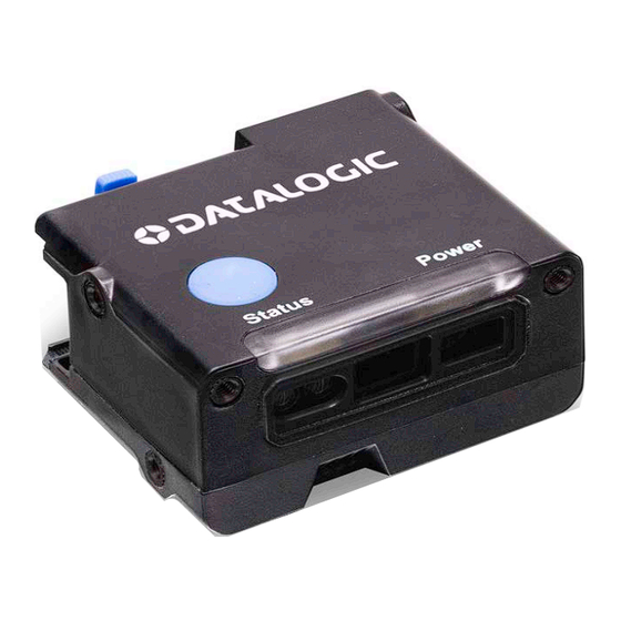
Setting Up the Reader Parts of the Reader GFS4520 model 1. Power/Status LEDs 2. Scan window 3. Beeper output 4. Trigger 5. USB cable retainer (only for GFS4520) QUICK REFERENCE GUIDE... -
Page 14: Attaching And Retaining The Usb Cable (Gfs4520 Model Only)
Setting Up the Reader Attaching and Retaining the USB Cable (GFS4520 Model Only) 1. While pressing the retainer’s locking wings, slide to pull it out of its housing. 2. Rotate the retainer clockwise and insert the USB cable. 3. Set back the retainer by rotating it counterclockwise and push until the cable is firmly locked. - Page 15 Setting Up the Reader Video Tutorial QUICK REFERENCE GUIDE...
-
Page 16: Connecting To The Host Interface
Follow the steps indicated by the pictures below to con- nect the reader to the Host, according to the communica- tion cable available. RS-232 USB/RS-232 (with multi-interface connector) NOTE: Refer to the Product Reference Guide for the list of compatible Datalogic cables. GRYPHON™ I GFS4500... -
Page 17: Using The Gryphon™ I Gfs4500
Using the Gryphon™ I GFS4500 USING THE GRYPHON™ I GFS4500 The Gryphon™ GFS4500 normally functions by capturing and decoding codes. The reader is equipped with an inter- nal Motionix™ motion-sensing function which activates the aiming system on device motion. The intelligent aim- ing system indicates the field of view which should be positioned over the bar code. - Page 18 Successful reading is signaled by an audible tone plus a goodread green spot LED indicator. Reference the Gryphon™ GFS4500 Product Reference Guide (PRG) on the Datalogic website for more information about this fea- ture and other programmable settings. Figure 4. Relative Size and Location of Gryphon™...
-
Page 19: Selecting The Interface Type
For interfaces other than those listed in this manual, see the Gryphon™ I GFS4500 Product Reference Guide (PRG), available online at www.datalogic.com. RS-232 (GFS4550 ONLY) Select RS232-STD RS-232 standard interface Select RS232-WN RS-232 Wincor-Nixdorf... -
Page 20: Usb Interface (Gfs4520 & Gfs4590 Only)
Selecting the Interface Type USB Interface (GFS4520 & GFS4590 only) The reader attaches directly to a USB host or a powered USB hub and is powered by it. No additional power supply is required. The reader auto-detects the USB and defaults to the USB-COM interface. - Page 21 USB-COM Select USB-COM Simulate a serial interface USB COMPOSITE Select USB-Composite Combines USB-KBD emulation and USB-COM USB-OEM Refer to the PRG or Aladdin for USB-OEM (for use with OPOS/UPOS/JavaPOS) a. Download the correct USB-COM driver from: https://www.datalogic.com QUICK REFERENCE GUIDE...
-
Page 22: Country Mode
Selecting the Interface Type Country Mode This feature specifies the country/language supported by the keyboard. Several languages are supported: COUNTRY MODE ENTER/EXIT PROGRAMMING MODE ★ Country Mode = U.S. Country Mode = Belgium Country Mode = Croatia* Country Mode = Czech Republic* Country Mode = Denmark* GRYPHON™... - Page 23 Selecting the Interface Type COUNTRY MODE (CONTINUED) Country Mode = France Country Mode = French Canadian* Country Mode = Germany Country Mode = Hungary* Country Mode = Italy Country Mode = Japanese 106-key* Country Mode = Lithuanian* QUICK REFERENCE GUIDE...
- Page 24 Selecting the Interface Type COUNTRY MODE (CONTINUED) Country Mode = Norway* Country Mode = Poland* Country Mode = Portugal* Country Mode = Romania* Country Mode = Slovakia* Country Mode = Spain Country Mode = Sweden GRYPHON™ I GFS4500...
-
Page 25: Programming
Programming can also be performed using the Datalogic Aladdin™ Configuration application, which is download- able from the Datalogic website listed on the back cover of this manual. This multi-platform utility program allows device configuration using a PC. It communicates with the device using a serial or USB cable and can also create con- figuration barcodes to print. -
Page 26: Configure Other Settings
Programming Configure Other Settings Additional programming bar codes are available in the PRG to allow customization of programming features. If your installation requires different programming than the standard factory default settings, refer to the PRG. Resetting Product Defaults If you are not sure what programming options have been set in your reader, or you have changed some options and want your custom factory settings restored, scan the bar code below to reset the reader to its initial configuration. -
Page 27: Numlock
NUMLOCK NUMLOCK This option specifies the setting of the Numbers Lock (Numlock) key while in keyboard wedge interface. This only applies to alternate key encoding interfaces. It does not apply to USB keyboard. NUMLOCK ENTER/EXIT PROGRAMMING MODE ★ ? š Numlock = Numlock key unchanged Numlock = Numlock key toggled QUICK REFERENCE GUIDE... -
Page 28: Reading Parameters
Reading Parameters READING PARAMETERS Move the reader toward the target and center the aiming pattern and illumination system to capture and decode the image. The aiming system will briefly switch off after the acquisition time, and if no code is decoded will switch on again before the next acquisition. -
Page 29: Operating Modes
Operating Modes GREEN SPOT DURATION (CONTINUED) Medium (500 ms) Long (800 ms) ★ = default value OPERATING MODES The reader can operate in one of several scanning modes. NOTE: See the PRG for further information on the operation of reading modes, and additional pro- grammable features. - Page 30 Operating Modes OPERATING MODE ENTER/EXIT PROGRAMMING MODE Operating Mode = On Line Operating Mode = Serial On Line Operating Mode = Alway On Operating Mode = Object Sense Operating Mode = Test Mode GRYPHON™ I GFS4500...
-
Page 31: Pick Mode
Pick Mode PICK MODE This option specifies the ability of the reader to decode labels only when they are close to the center of the aiming pattern, which is the area indicated by the red cross. Pick Mode is a Decoding and Transmission process where bar codes that are not within the configurable distance from the center of the aiming pattern are not acknowledged or transmitted to the host. -
Page 32: Energy Saving
Energy Saving ENERGY SAVING The following barcodes contain predefined configurations to reduce the power consumption of the scanner. ENERGY SAVING ★ Energy Saving = Off Energy Saving = Medium Energy Saving = Max Energy Saving = Medium Volume of Good Read Beep is reduced to Medium •... -
Page 33: Performance Preset
Performance Preset Refer to the following table for an estimation of power saving in the different presents: ENERGY SAVING TYPICAL POWER SAVING Off (Default) Medium 10-15% 20-25% PERFORMANCE PRESET The scanner can be configured to match different perfor- mance needs, depending on the application.The following barcodes contain predefined configurations to be applied. -
Page 34: Technical Specifications
Technical Specifications TECHNICAL SPECIFICATIONS The following table contains Physical and Performance Characteristics, User Environment and Regulatory infor- mation. PHYSICAL CHARACTERISTICS Black. Other colors and custom logo options are Colors available for minimum quantity purchase. GFS4500: 2.8 x 4.8 x 5.5 cm / 1.1 x 1.9 x 2.2 in. Dimensions GFE4500: 2.0 x 2.7 x 4.8 cm / 0.8 x 1.1 x 1.9 in. - Page 35 60 full-frame/s Reading Angles Pitch: +/- 60°; Roll (Tilt): +/- 180°; Skew (Yaw): +/- 60° Beeper (Adjustable Tone and volume); Datalogic ‘Green Spot’ Reading Indicators Good Read Feedback; Top-Front Good Read LED with Adjustable brightness 1D Linear: 0.076 mm / 3 mils Resolution (Maxi- Data Matrix: 0.13 mm / 5 mils...
-
Page 36: Rs-232 Electrical Connections (Gfs4550 Only)
Technical Specifications RS-232 Electrical Connections (GFS4550 only) 9-PIN CONNECTOR Trigger signal input (see Figure 5 Trigger Figure 6 on next page) Transmit Data (output from scanner) Receive Data (input to scanner) Not connected Ground +5Vdc Clear To Send (input to scanner) Request To Send (output from scanner) Output signal (see... -
Page 37: Input Connection - Typical Layout
Technical Specifications Input connection - Typical layout ENTER/EXIT PROGRAMMING MODE Figure 5. NPN configuration NPN configuration = Set Input Configuration to NPN QUICK REFERENCE GUIDE... - Page 38 Technical Specifications Figure 6. PNP configuration ★ PNP configuration = Set Input Configuration to PNP Vext: 5.0 Vdc to 14.0 Vdc, I_IN: 4.0 mA max Figure 7. NPN or PNP configuration Ensure both sides are configured the same way. Vext: 5.0 Vdc to 14.0 Vdc, I_IN: 4.0 mA max GRYPHON™...
-
Page 39: Output Connection - Typical Layout
Technical Specifications Output connection - Typical layout ENTER/EXIT PROGRAMMING MODE Figure 8. NPN output configuration ★ NPN configuration = Set Output Configuration to NPN USER INTERFACE Vext [14V max.] GFS4550 / GFE4590 NPN Output Connection Figure 9. PNP output configuration PNP configuration = Set Output Configuration to PNP GFS4550 / GFE4590 USER INTERFACE... -
Page 40: Gfs4500 Dimensions
Technical Specifications GFS4500 Dimensions GRYPHON™ I GFS4500... -
Page 41: Led And Beeper Indications
LED and Beeper Indications LED AND BEEPER INDICATIONS Button and LED Status The top of the product has a button and three indicator LEDs: ON = Power ON Blinking = USB enumera- tion (USB version only) or POWER LED FW Upgrade (green) OFF = Power OFF or Limited Scanning Mode or Standby... - Page 42 LED and Beeper Indications INDICATION BEEPER Upper LED flashes/ blinks on power-up, however, this may be Imager beeps four too rapid to view. With times at highest fre- Power-up a USB interface, the quency and volume LED blinks until enu- upon power-up.
-
Page 43: Troubleshooting
Troubleshooting TROUBLESHOOTING POSSIBLE PROBLEM POSSIBLE CAUSE SOLUTION Check system power. No power to the Ensure power supply is Nothing happens when imager. connected. the scan button is pushed Interface or power Ensure all cable con- cables are loose. nections are secure. Ensure reader is pro- grammed to read the Imager not pro-... -
Page 44: Using The Gfs4400 Adapter
Using the GFS4400 Adapter USING THE GFS4400 ADAPTER Customers can take advantage of the accessory “Mount- ing Adapter to replicate the GFS4400 fixing holes” (Part Number: MA-4500-BK) to replace their setups based on previous Gryphon I GFS4400 family, with the new Gry- phon I GFS4500. - Page 45 Using the GFS4400 Adapter Figure 10. Comparison of front views of Gryphon GFS4400 (left) and Gryphon GFS4500 with Mounting Adapter (right) Figure 11. Comparison of bottom views of Gryphon GFS4400 (left) and Gryphon GFS4500 with Mounting Adapter (right) QUICK REFERENCE GUIDE...
-
Page 46: Warranty
Datalogic, unless otherwise agreed in an applicable writing by Datalogic. Datalogic will not be liable under the warranty if the Product has been exposed or subjected to any: (1) maintenance, repair, installation, han- dling, packaging, transportation, storage, operation or use that is improper or otherwise not in compliance with Datalogic’s instruction;... -
Page 47: Ergonomic Recommendations
Ergonomic Recommendations ERGONOMIC RECOMMENDATIONS CAUTION: In order to avoid or minimize the poten- tial risk of ergonomic injury, follow the recom- mendations below. Consult with your local Health & Safety Manager to ensure that you are adhering to your company’s safety programs to prevent employee injury. -
Page 48: Technical Support
Technical Support. Reseller Technical Support An excellent source for technical assistance and informa- tion is an authorized Datalogic reseller. A reseller is acquainted with specific types of businesses, application software, and computer systems and can provide individu- alized assistance. - Page 52 ©2023 Datalogic S.p.A. and /or its affiliates. • All rights reserved • Without limiting the rights under copyright, no part of this documentation may be reproduced, stored in or introduced into a retrieval system, or transmitted in any form or by any means, or for any purpose, without the express written permission of Datalogic S.p.A.
Need help?
Do you have a question about the Gryphon GFS4500 and is the answer not in the manual?
Questions and answers