Table of Contents
Advertisement
Quick Links
Advertisement
Table of Contents

Related Manuals for d&b audiotechnik Z5778


Summary of Contents for d&b audiotechnik Z5778
- Page 1 Z5778/Z5779 Rigging manual 1.2 en...
- Page 2 General information Z5778/Z5779 Rigging manual Version: 1.2 en, 06/2023, D2770.EN .01 Copyright © 2023 by d&b audiotechnik GmbH & Co. KG; all rights reserved. Keep this document with the product or in a safe place so that it is available for future reference.
-
Page 3: Table Of Contents
1.4.1 Wind loads................5 1.5 Operational safety..............6 Rigging concept and components......... 7 2.1 Mounting frames and adapter........... 7 2.1.1 Z5778 XSL Top mounting frame..........8 2.1.2 Z5779 XSL-SUB Mounting frame........... 9 2.1.3 Z5783 XSL-SUB Adapter frame........... 10 2.2 Locking pins................11 2.3 Ring cotters................ -
Page 4: Safety
In case there is any doubt as to the proper functioning and safety of the items, these must be withdrawn from use immediately. Please also refer to Þ Chapter 6 "Care and maintenance" on page 25. d&b Z5778/Z5779 Rigging manual 1.2 en... -
Page 5: System Components And Weights/Load Capacity
66 kg (146 lb) Z5778 XSL Top mounting frame Rigging components The Z5778 XSL Top mounting frame is designed to support a total Z5778 XSL Top mounting frame 10 kg (22 lb) system weight of 500 kg (1100 lb) - SWL including all rigging... -
Page 6: Operational Safety
▪ When chain hoists are in operation, ensure that there is nobody directly underneath or in the vicinity of the load. ▪ Do not under any circumstances climb on the array. d&b Z5778/Z5779 Rigging manual 1.2 en... -
Page 7: Rigging Concept And Components
Rigging concept and components 2.1 Mounting frames and adapter The d&b XSL cabinets are supplemented by two dedicated mounting frames (Z5778 XSL Top mounting frame and Z5779 XSL- SUB Mounting frame) and the additional Z5783 XSL-SUB Adapter frame. These components allow setting up the following array... -
Page 8: Z5778 Xsl Top Mounting Frame
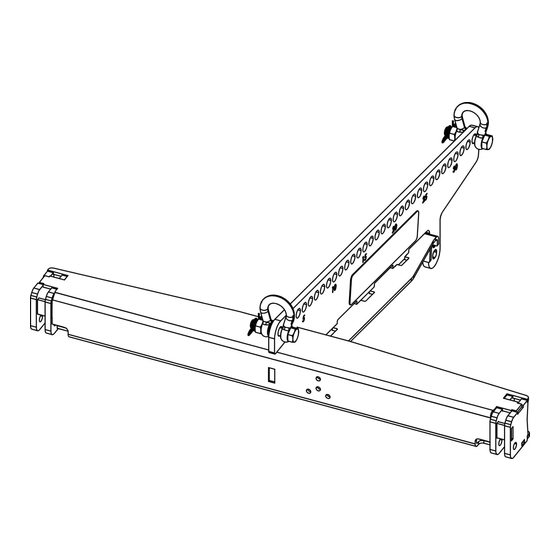
Rigging concept and components 2.1.1 Z5778 XSL Top mounting frame Intended use The Z5778 XSL Top mounting frame is designed to support a total system weight of 500 kg (1100 lb) - SWL including all rigging components. This allows the suspension of a maximum of 12 x XSL TOP cabinets. -
Page 9: Z5779 Xsl-Sub Mounting Frame
The center hole serves as the exit for the laser beam, while the three surrounding holes allow for the adjustment of the ArraySight sender unit, if necessary. Instruction label providing vital safety and rigging instructions. Z5779 XSL-SUB Mounting frame dimensions in mm [inch] Weight 11 kg (24 lb) d&b Z5778/Z5779 Rigging manual 1.2 en... -
Page 10: Z5783 Xsl-Sub Adapter Frame
XSL TOP cabinets, the Splay link of the frame is used to attach the first cabinet underneath XSL-SUB cabinets. Instruction label providing vital safety and rigging instructions. Z5783 XSL-SUB Adapter frame dimensions in mm [inch] Weight 14 kg (31 lb) d&b Z5778/Z5779 Rigging manual 1.2 en... -
Page 11: Locking Pins
4. Release the button to Lock the pin ( [L]). 5. Recheck the Locking pin is securely locked by briefly pulling the Locking pin towards you. Locking pin functionality d&b Z5778/Z5779 Rigging manual 1.2 en... -
Page 12: Ring Cotters
3. Refit and lock Refit the ring cotter by pushing the straight wire shaft through the hole and pressing the front wire loop underneath the straight wire shaft. d&b Z5778/Z5779 Rigging manual 1.2 en... -
Page 13: Rigging Mechanism Of The Cabinets
This setting is used to prevent the cabinets from folding up. Fig. 1: SUB to Frame Fig. 2: SUB to SUB, 0° splay Fig. 3: SUB to SUB, 2.5° splay, Fig. 4: SUB to SUB, 2.5° splay, free blocked d&b Z5778/Z5779 Rigging manual 1.2 en... -
Page 14: Splay/Rear Link Mechanism
In tension mode, pin [3] is always inserted in the 0° hole at the bottom of the inner hole grid to fix the Splay link in place. As an example, the graphic opposite shows the pin settings for 2° splay in tension mode. d&b Z5778/Z5779 Rigging manual 1.2 en... - Page 15 4. Slightly lift the bottom cabinet until the hook of the upper Set splay angle (e.g. 2°) cabinet has engaged. 5. Lower the bottom cabinet and reinsert the second Locking pin (Safety pin [S]). d&b Z5778/Z5779 Rigging manual 1.2 en...
-
Page 16: Suspension Of The Frames
50 mm (2”). Attachment Choose the appropriate hole position on the center bar according to the ArrayCalc calculation and attach the clamp correspondingly. Note: Please observe the relevant mounting instructions which are enclosed with the clamp. d&b Z5778/Z5779 Rigging manual 1.2 en... -
Page 17: Arrays And Assembly Procedures
▪ Clear the working areas and ensure there is enough space to set up and lift the array. ▪ Check that the hoists are exactly in the specified position. ▪ Ensure the chains are not twisted. d&b Z5778/Z5779 Rigging manual 1.2 en... -
Page 18: Xsl Top Array
4.2 XSL TOP array 4.2.1 Remarks and limitations NOTICE! In combination with the Z5778 XSL Top mounting frame, a maximum 12 x XSL TOP cabinets can be flown. 4.2.2 Order of assembly 1. Attach the Mounting frame to the first TOP cabinet To attach the frame to the first cabinet, proceed as follows: 1. - Page 19 System check functions or Channel mute switches and a test signal to check the correct operation and routing of all channels and cabinets. ▪ Alternatively, check the wiring using the Array verification function in R1. d&b Z5778/Z5779 Rigging manual 1.2 en...
-
Page 20: Xsl-Sub Column
4. At the front, insert the Locking pins of the cabinet's front rigging strands on both sides. 5. On the bottom cabinet, check the Rear link is properly fitted into the rear rigging strand. 6. Insert both Locking pins. d&b Z5778/Z5779 Rigging manual 1.2 en... - Page 21 System check functions or Channel mute switches and a test signal to check the correct operation and routing of all channels and cabinets. ▪ Alternatively, check the wiring using the Array verification function in R1. d&b Z5778/Z5779 Rigging manual 1.2 en...
-
Page 22: Mixed Array Configuration
3. Reinsert the Locking pins on both sides. 4. At the rear, check the Rear link of the cabinet is properly fitted into the rear rigging slot of the frame and reinsert both Locking pins. d&b Z5778/Z5779 Rigging manual 1.2 en... - Page 23 System check functions or Channel mute switches and a test signal to check the correct operation and routing of all channels and cabinets. ▪ Alternatively, check the wiring using the Array verification function in R1. d&b Z5778/Z5779 Rigging manual 1.2 en...
-
Page 24: Rechecking, Hoisting And Secondary Safety
The secondary safety device must be attached to the front of the frames using one of the first five holes. d&b Z5778/Z5779 Rigging manual 1.2 en... -
Page 25: Care And Maintenance
If a ring cotter can no longer be properly fitted to the fixing bolt and locked, it must be exchanged. Condition of the ring cotter [a]: Ring cotter OK [b]: Exchange the ring cotter d&b Z5778/Z5779 Rigging manual 1.2 en... -
Page 26: Manufacturer's Declarations
▪ Z0772 XSL12 ▪ Z0774 XSL-SUB d&b XSL rigging components (including all additional components.) ▪ Z5778 XSL Top mounting frame ▪ Z5779 XSL-SUB Mounting frame ▪ Z5783 XSL-SUB Adapter frame by d&b audiotechnik GmbH & Co. KG. All product variants are included, provided they correspond to the original technical version and have not been subject to any later design or electromechanical modifications. - Page 27 www.dbaudio.com...
Need help?
Do you have a question about the Z5778 and is the answer not in the manual?
Questions and answers