Table of Contents
Advertisement
Quick Links
Advertisement
Table of Contents

Related Manuals for d&b audiotechnik Q-Series


Summary of Contents for d&b audiotechnik Q-Series
- Page 1 Q-Series Rigging manual (1.2EN) Z5159 Q Flying frame Z5156 Q Flying adapter...
- Page 2 Additional information and/or references. Symbols on the equipment Please refer to the information in the operating manual. General Information Q-Series Rigging manual Version 1.2EN, 02/2007, D2951.E.01 Copyright © 2007 by d&b audiotechnik AG; all rights reserved. Keep this manual with the product or in a safe place so that it is available for future reference.
-
Page 3: Table Of Contents
1.1. Intended use..................4 1.2. General safety instructions...............4 1.3. Load capacity/System safety............4 1.3.1. ArrayCalc / TI 385...............4 2. Q-Series array with the Z5159 Q Flying frame....5 2.1. Rigging components.................6 2.1.1. Z5159 Q Flying frame............6 2.1.2. Z5155 Q Hoist connector chain..........6 2.1.3. Z5154 Q Rigging set............6 2.2. -
Page 4: Safety Precautions
ArrayCalc array calculator. Under no circumstances climb on the array. 1.3.1. ArrayCalc / TI 385 The use of ArrayCalc is described in "TI 385 J-Series and Q-Series system design, d&b ArrayCalc" which is supplied with the Q Flying frame. ArrayCalc can be downloaded at www.dbaudio.com. -
Page 5: Q-Series Array With The Z5159 Q Flying Frame
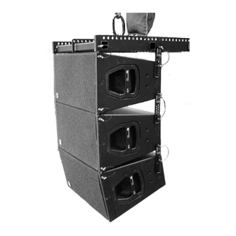
2. Q-Series array with the Z5159 Q Flying frame Z5151 Q Splay link Z5153 Locking pins 8 mm Z5152 Q Front link 0 TO FRAME position between flying frame and first cabinet Fig. 1: Q-Series rigging assembly Q-Series Rigging manual (1.2EN) -
Page 6: Rigging Components
1t motor chain containers. Fig. 4: Z5155 Q Hoist connector chain 2.1.3. Z5154 Q Rigging set One set is required for each Q-Series cabinet within a vertical array. The rigging set includes the following components: 2 x Z5151 Q Splay link [a]... -
Page 7: Preparation For The Set Up
(Fig. 8). Please refer to the Z5160 Q Load adapter manual. Fig. 7: Half grid using 2 x 1t Shackle Fig. 8: Quad grid using the Z5160 Q Load adapter Q-Series Rigging manual (1.2EN) Page 7 of 20... - Page 8 If this is not possible attach the cable pick directly under the chain hoist. Fig. 13: Splay link setting for first Q1 Fig. 15: Splay link setting for first Q-SUB Fig. 14: First cabinet attached Q-Series Rigging manual (1.2EN) Page 8 of 20...
-
Page 9: Alternative Set Up
Front links. to lift the cabinets Connect Front and Splay links to the bottom of the cabinet and add the next one in the same manner. Q-Series Rigging manual (1.2EN) Page 9 of 20... -
Page 10: Final Check Of The Array
Add Q1 cabinets one by one using the Z5151 Q Front links, Z5152 Q Splay links and Z5153 Locking pins 8 mm. Fig. 21: Q1s in a ground stacked set up on Z5159 Q Flying frame Q-Series Rigging manual (1.2EN) Page 10 of 20... -
Page 11: Z5156 Q Flying Adapter
For safety reasons the final array must be fitted with an additional Fig. 26: Q cabinet quick lock mechanism safety device which is independent of the suspension points. A detailed description is given in section 4. Secondary safety on page 12. Q-Series Rigging manual (1.2EN) Page 11 of 20... -
Page 12: Secondary Safety
(pickup point - Fig. 29a). The shackles may also be placed diagonally around the pickup point - Fig. 29b. Fig. 29: Secondary safety - Type 2 Q-Series Rigging manual (1.2EN) Page 12 of 20... -
Page 13: Secondary Safety At Z5156 Q Flying Adapter
[R4] on both sides of the cabinet, passing the steel rope through the Flying pins or the Safety eye bolts and attaching it to the securing pickup point. [CR] [R2] Fig. 30: Sockets for secondary safety Q-Series Rigging manual (1.2EN) Page 13 of 20... -
Page 14: Aiming And Securing Of The Array
With arrays of up to three cabinets the standard rigging sockets on the cabinets may be used (Fig. 31). WARNING! To angle an array of more than three Q-Series cabinets an additional Z5159 Q Flying frame has to be attached to the lowest cabinet of the column. All additional wires or hoists have to be connected to the Q Flying frame and not to the cabinets rigging sockets (Fig. -
Page 15: Wind Loads
Stop the event and make sure that no one is left within the vicinity of the array. Lower down and secure the array. Q-Series Rigging manual (1.2EN) Page 15 of 20... -
Page 16: Care And Maintenance / Disposal
During transport ensure the rigging components are not stressed or damaged by mechanical forces. Use suitable transport cases. Due to their surface treatment the Q-Series rigging components are temporary protected against moisture. However, ensure the components are in a dry state while stored or during transport and use. -
Page 17: Ec Declaration Of Conformity
EC Declaration of Conformity within the meaning of the EC Machine Directive 98/37/EEC We hereby declare that the equipment designated below is designed and built in the version sold by us in such a way as to comply with the relevant fundamental safety and health criteria of the applicable EC Directive(s). This declaration shall cease to be valid if alterations are made to the equipment without our prior agreement. - Page 18 d&b audiotechnik AG, Eugen-Adolff-Str. 134, D-71522 Backnang, Germany, Phone +49-7191-9669-0, Fax +49-7191-95 00 00_______...
Need help?
Do you have a question about the Q-Series and is the answer not in the manual?
Questions and answers