Table of Contents
Advertisement
Available languages
Available languages
Quick Links
PREMIER 24V
Disegni tecnici per progetti
Dessins techniques pour les projets
Technical drawings for projects
Technische Zeichnungen für Projekte
Dibujos técnicos para proyectos.
Scarica questo manuale sul tuo cellulare
Téléchargez ce manuel sur votre mobile
Download this manual on your mobile
Laden Sie dieses Handbuch auf Ihr Handy herunter
Descarga este manual en tu móvil
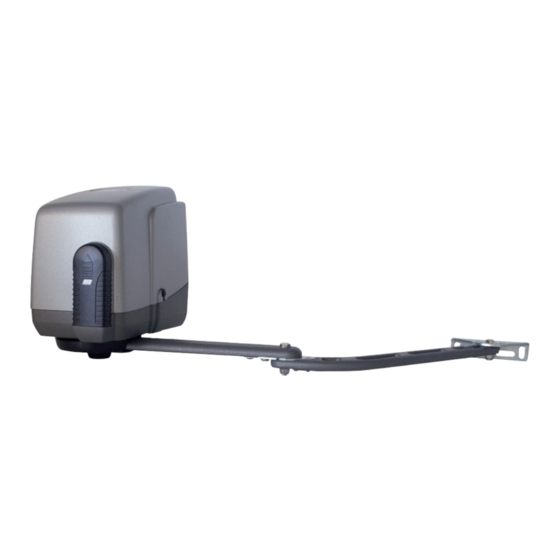
Operatore
Operateur
Operator
Torantrieb
Operador
PREMIER 24V (Master)
PREMIER 24V (Slave)
KIT PREMIER 24V
ITALIANO pag. 05 / FRANÇAIS pag. 19 / ENGLISH page 33 / DEUTSCH pag. 47 / ESPAÑOL pag. 61
con / avec / with / mit
Alimentazione
Alimentation
Power Supply
Stromspannung
Alimentacion
230V 50/60Hz
24Vdc
230V 50/60Hz
Il corretto funzionamento dell'operatore è garantito solo se viene gestito da un quadro di comando RIB
Le bon fonctionnement de l'opérateur n'est garanti que s'il est géré par un panneau de contrôle RIB
The correct operation of the operator is guaranteed only if it is managed by a RIB control panel
Die korrekte Bedienung des Bedieners ist nur gewährleistet, wenn er von einem RIB-Bedienpanel verwaltet wird
El funcionamiento correcto del operador solo está garantizado si está gestionado por un panel de control RIB
B2 24V-CRX
Peso max cancello
Coppia max
Poids maxi portail
Couple maxi
Max gate weight
Max torque
Max Torgewicht
Max. Drehmoment
Peso máx verja
Coppia max
300 kg / 660 lbs
150 Nm
Manuali online interattivi
Manuels interactifs en ligne
Interactive online manuals
Interaktive Online-Handbücher
Manuales interactivos en línea.
Vedere pagina 18
Voir page 32
See page 46
Siehe Seite 60
Ver página 74
Codice
Code
Code
Kode
Codigo
AA18018
AA18014B
AD18018
Advertisement
Table of Contents

Related Manuals for RIB AA18014B


Summary of Contents for RIB AA18014B
- Page 1 Le bon fonctionnement de l’opérateur n’est garanti que s’il est géré par un panneau de contrôle RIB The correct operation of the operator is guaranteed only if it is managed by a RIB control panel Die korrekte Bedienung des Bedieners ist nur gewährleistet, wenn er von einem RIB-Bedienpanel verwaltet wird El funcionamiento correcto del operador solo está...
- Page 2 2° - En ce qui concerne la section et le type des câbles, RIB conseille d’utiliser un câble de 2° - Per la sezione ed il tipo dei cavi la RIB consiglia di utilizzare un cavo di tipo H05RN-F con type H05RN-F ayant une section minumum de 1,5 mm 2 et de toute façon, s’en tenir à...
- Page 3 Kontaktöffnung von 3 mm), der ein von den internationalen Normen 2° - For the section and the type of the cables RIB advices to use a cable of H05RN-F type anerkanntes Konformitätszeichen besitzt. Solch ein Geraet muss vor Vandalismus with 1,5 sqmm minimum section and, however, to keep to the IEC 364 and installation geschuetzt werden (z.B.mit einen Schluesselkatsten in einem Panzergehaeuse).
- Page 4 L’eliminazione dei materiali va fatta rispettando le norme vigenti. Non gettate il vostro 2° - Para la sección y el tipo de los cables, RIB aconseja utilizar cables de tipo H05RN-F con apparecchio scartato, le pile o le batterie usate nei rifiuti domestici. Avete la responsabilità di sección mínima de 1,5 mm 2 e igualmente atenerse a la norma IEC 364 y a las normas de...
- Page 5 LAYOUT IMPIANTO CARATTERISTICHE TECNICHE PREMIER 24V è un operatore irreversibile utilizzato per movimentare cancelli a battente con ante lunghe fino a 3 m (Fig. 1). PREMIER 24V è stato concepito per funzionare senza finecorsa elettrici, ma solo meccanici. Quando è arrivato in battuta il motore funziona ancora per qualche secondo, fino a quando non interviene il timer di funzionamento della centralina di comando o il sensore di corrente.
- Page 6 INSTALLAZIONE PREMIER Componenti da installare secondo la norma EN 12453 CONTROLLO PRE-INSTALLAZIONE USO DELLA CHIUSURA Le ante devono essere solidamente fissate ai cardini delle colonne, non devono flettere TIPO DI COMANDO durante il movimento e devono muoversi senza attriti. Persone esperte Persone esperte Persone Prima d’installare PREMIER 24V è...
- Page 7 FISSAGGIO ATTACCO MOTORE A COLONNA (D) Durante l’installazione di PREMIER 24V è necessario rispettare alcune misure per avere un corretto movimento dell’anta (vedi fig. 6-8). MONTAGGIO LEVE DI TRAINO CON DISPOSITIVO DI BLOCCAGGIO ANTI-INTRUSIONE (E) Eseguire l’assemblaggio delle leve come da figura 5. Attenzione: avvitare a fondo le viti V ed W dopodichè...
-
Page 8: Manutenzione
REGOLAZIONE FINECORSA MECCANICI Per posizionare i fermi agire come da schema (Fig. 8). Per ottenere la chiusura desiderata, a cancello completamente chiuso si dovrà spostare il fermo (F) contro la leva di traino bloccandolo poi serrando le due viti 6x20 inox ad esagono incassato con una chiave a brugola n°... -
Page 9: Collegamenti Elettrici
code ABB2070 B2 24V-CRX 230V 50/60Hz COLLEGAMENTI ELETTRICI code ABB2071 B2 24V-CRX 120V/60Hz code AC08070 B2 24V solo scheda... - Page 10 LOW SP Alimentazione 230 Vac 50/60 Hz - esterna alla scheda RADIO Connettore per modulo radio ACG8069 (120 V 60 Hz a richiesta) Connettore per radio ricevitore RIB ad innesto con RADIO A+TEST Positivo per alimentazione autotest fotocellule alimentazione a 24Vdc...
- Page 11 B - IMPOSTAZIONI questo impatti contro cose o persone (in conformità alle norme en vigenti - verificare sempre con apposito strumento il rispetto dei valori imposti dalla norma EN12453. Si attivi il DIP 14 per la corretta misurazione). DIP 1 (ON) - CONTROLLO SENSO DI ROTAZIONE DEI MOTORI (PUNTO C) Con impatto in apertura, inverte il movimento in chiusura per 1 so e poi si ferma.
- Page 12 R-AUX funziona normalmente come luce di cortesia per 3 minuti. DIP 13 su ON (di fabbrica): si possono memorizzare telecomandi a codice fisso SUN: Tramite App RIB GATE è possibile configurare il funzionamento di questo relé a piacere. SUN 2CH bicanale - tasti blu e led bianco cod. ACG6052 La programmazione può...
-
Page 13: Funzionamento Accessori Di Sicurezza
da 2 toni del buzzer. 3 - Successivamente il led DL12 rimane attivo arancio lampeggiante per 10 s ed è possibile COLPO DI AGGANCIO SERRATURA ELETTRICA inserire nuovi codici come da procedure sopra descritte. Mettere il DIP 11 su ON per abilitare il colpo di aggancio della serratura elettrica in chiusura. 4 - Riposizionare DIP 1, 2, 3 su OFF. -
Page 14: Risoluzione Problemi
fotocellule (oppure coste) funzionano ancora interrompendo la manovra in atto. rispetto di isolamento doppio o rinforzato rispetto alle parti a tensione pericolosa. Nota 2: il pulsante di stop non è considerato una sicurezza da bypassare in questa modalità, - Eventuali circuiti esterni collegati alle uscite del quadro elettronico, devono essere eseguiti pertanto se viene premuto o è... - Page 15 TABELLA RIASSUNTIVA ALLARMI VISIVI E SONORI SEGNALAZIONI IN FASE DI PROGRAMMAZIONE EVENTO STATO BUZZER STATO LAMPEGGIATORE STATO LED DL1 DIP 1 ON (modo uomo presente) Spento Spento Lampeggia 250 ms ON/OFF Oppure guasto ad una sicurezza DIP 2 ON (programmazione corsa totale) Spento Spento Lampeggia 500 ms ON/OFF...
- Page 16 Costa con resistenza 8,2 KΩ. Togliere la resistenza o configurare l’ingresso EDGE tramite App Il buzzer emette 2 toni prolungati e il cancello non si muove RIB GATE Il telecomando non funziona. Led DL12 acceso rosso fisso Mancanza modulo radio nel connettore J6 o modulo radio guasto.
- Page 17 APP8054 Scheda APP+ APP8050 Scheda APP per gestire la centrale di comando per gestire la centrale di comando tramite Bluetooth 4.2 tramite Bluetooth 4.2 APP8064 Modulo Wi-Fi per Scheda APP8066 Modulo RJ45 per Scheda APP+ APP+ per gestire la centrale tramite rete per gestire la centrale tramite rete Wi-Fi locale (WLAN) dati locale (LAN)
- Page 18 CASSAFORTE STONE LEVA LUNGA Contenitore di sicurezza per impedire l’agibilità ai dispositivi di comando. Viene fornita di LEVA LUNGA per cancelli con cerniera distante fino a 50 cm dal bordo colonna. fabbrica completa di pulsante a bascula (apre-chiude) e sblocco. Necessita del cavo cod. cod.
-
Page 19: Caracteristiques Techniques
SCHÉMA DÉTAILLÉ DE L’INSTALLATION CARACTERISTIQUES TECHNIQUES PREMIER 24V est un opérateur irréversible utilisé pour faire fonctionner des portails ayant des battants d’une longueur allant jusqu’à 3 m (Fig. 1). PREMIER 24V a été conçu pour fonctionner sans fins de course électriques, mais seulement avec des fins de course mécaniques. - Page 20 INSTALLATION PREMIER CONTROLE PRE-INSTALLATION Parties à installer conformément à la norme EN 12453 Le portail à battant doit être solidement fixé aux cardans des colonnes, ne doit pas flechir USAGE DE LA FERMETURE pendant le mouvement et doit pouvoir manoeuvrer sans effort. TYPE DE COMMANDE Personne expertes Personne expertes...
- Page 21 FIXATION ATTACHE MOTEUR A COLONNE (D) Durant l’installation de PREMIER 24V, il est nécessaire de respecter certaines mesures pour avoir un mouvement du battant correct (voir fig. 6-8). MONTAGE LEVIERS D’ENTRAINEMENT AVEC DISPOSITIF DE BLOCAGE ANTI-INTRUSION (E) Effectuer l’assemblage des leviers selon la figure 5. Attention : Visser les vis V et W à...
-
Page 22: Maintenance
REGLAGE FINS DE COURSE MECANIQUES Pour positionner les butées, agir comme décrit sur le schéma (Fig. 8). Pour obtenir la fermeture désirée, quand le portail est complètement fermé, il faudra déplacer la butée contre le levier d’entraînement en le bloquant et en serrant ensuite les deux vis inox hexagonales encaissées 6x20 avec une clef Allen n°5. -
Page 23: Branchements Électriques
code ABB2070 B2 24V-CRX 230V 50/60Hz BRANCHEMENTS ÉLECTRIQUES code ABB2071 B2 24V-CRX 120V/60Hz code AC08070 B2 24V seule carte... - Page 24 Alimentation 230 Vac 50/60 Hz - externe à la fiche RADIO Connecteur pour module radio ACG8069 (120 V 60 Hz sur demande) Connecteur pour radio récepteur RIB à enclenchement avec RADIO A+TEST Positif pour alimentation autotest photocellules alimentation à 24Vdc BATTERY CHARGER Connecteur pour fiche de recharge batterie à...
- Page 25 B - RÉGLAGES TRIMMER SENS Par usine activé et LED DL14 allumée (trimmer à mi-course) DIP 1 (ON) - COMMANDE SENS DE ROTATION DU MOTEURS (POINT C) La centrale B2 24V est dotée de détecteurs qui changent le sens du portail en cas d’impacts DIP 2 (ON) - PROGRAMMATION DES TEMPS (POINT D) avec des choses ou des personnes (en conformité...
- Page 26 DIP 13 ON (par usine): Vous pouvez mémoriser les télécommandes avec le code fixe SUN: Grâce à l’application RIB GATE, il est possible de configurer le fonctionnement de ce relais à SUN 2CH deux canaux - touches bleues et LED blanche cod.
- Page 27 3 - Pour terminer la programmation, laisser s’écouler 10 s, ou bien appuyer pendant un instant portail est ouvert, il le ferme. S’il est actionné pendant la fermeture du portail, il sur le bouton PROG. La LED DL12 arrête de clignoter. le rouvre.
-
Page 28: Solution Des Problemes
Le clignotant et le buzzer sont activés avec 2 tons toutes les 5 s pendant une minute. - Fréquence 50/60 Hz - Alimentation batterie 20-24 VCC BOUTON DE STOP (COM A+/STOP) - Puissance du transformateur 130 VA - 230 Vac / 18 Vac Durant n’importe quelle opération, le bouton de STOP arrête le portail. - Page 29 TABLEAU RÉCAPITULATIF ALARMES VISUELLES ET SONORES SIGNALISATIONS EN COURS DE PROGRAMMATION ÉVÉNEMENT ÉTAT BUZZER ÉTAT CLIGNOTEUR ÉTAT LED DL1 DIP 1 ON (mode homme mort) Éteint Éteint Clignote 250 ms ON/OFF Ou panne d'une sécurité DIP 2 ON (programmation course totale) Éteint Éteint Clignote 500 ms ON/OFF...
- Page 30 Barre palpeuse avec résistance 8,2 KΩ. Retirez la résistance ou configurez l'entrée EDGE avec Le buzzer émet 2 longs sons et le portail ne fonctionne pas l'application RIB GATE La télécommande ne fonctionne pas. Led DL12 allumé en rouge Absence de module radio dans le connecteur J6 ou module radio défectueux.
- Page 31 APP8054 Carte APP+ APP8050 Carte APP pour gérer le tableau de contrôle via pour gérer le tableau de contrôle via Bluetooth 4.2 Bluetooth 4.2 APP8064 Module Wi-Fi pour Carte APP8066 Module RJ45 pour Carte APP+ APP+ pour gérer le tableau de contrôle via pour gérer le tableau de contrôle via un réseau de données local (LAN) un réseau Wi-Fi local (WLAN)
- Page 32 COFFRE-FORT STONE BRAS LONG COFFret de sécurité empêchant tout accès non autorisé aux dispositifs de commande. BRAS LONG pour portails avec l’axe des gonds positionné jusqu’à 50 cm du bord du poteau Fourni de série, il est équipé d’un poussoir à bascule (ouverture-fermeture), ainsi que d’un code ACG8034 dispositif de déblocage de l’électro-frein.
-
Page 33: System Layout
SYSTEM LAY-OUT TECHNICAL FEATURES PREMIER 24V is an irreversible actuator designed for swing gates long up to 3 m (Pic. 1). PREMIER 24V works without electric limit switches, but with mechanical stoppers. A few seconds after that the gate leaf reaches the end of the stoke, either a time or a current sensor device, will cut out the motor (power supply). - Page 34 INSTALLATION PREMIER PRE-INSTALLATION CHECK LIST Parts to install according to EN 12453 standard The gate leaves must be firmly fixed to the hinges on the gate pillars, they must not flex during USE OF THE SHUTTER the movement and they must swing without any friction. COMMAND TYPE Skilled persons Skilled persons...
- Page 35 FIXING THE OPERATOR TO THE PILLAR (D) In order to carry out a proper installation of the operator, it is necessary to comply with the geometry measurement shown in the tables in Pic. 6 and 8. ASSEMBLING DRIVE ARM WITH THE ANTI-THEFT LOCKING DEVICE (E) Assemble the arms as shown in Pic.
- Page 36 ADJUSTMENT OF THE MECHANICAL STOPPERS Adjust the mechanical stoppers as shown in Pic. 8. When the gate is completely closed, slide the close mechanical stopper (F) against the arm. Then tighten it (key n. 5) with the two Allen screws 6x20 provided. In case an electric lock is fitted on the gate, the close mechanical stopper must be removed.
-
Page 37: Electric Connections
code ABB2070 B2 24V-CRX 230V 50/60Hz ELECTRIC CONNECTIONS code ABB2071 B2 24V-CRX 120V 60Hz code AC08070 B2 24V only pc board... - Page 38 RADIO Connector for radio module ACG8069 (120 V 60 Hz upon request) RADIO Connector for radio receiver RIB, 24 Vdc supply A+TEST + 24Vdc photocells self-test power supply BATTERY CHARGER Connector for charge card of 24 Vdc battery (code ACG4774)
-
Page 39: Led Signals
B - SETTINGS - with trimmer at max, the impact reaction occurs after 0,4 seconds (high sensitivity) IMPACT SENSOR ALARM DIP 1 (ON) - motors rotation direction control (point C) The alarm status will be displayed by the flasher which will remain active for one minute and DIP 2 (ON) - setting the times (point D) the buzzer with 3 tones every 5 s. - Page 40 ROTATIONAL DIRECTION CONTROL” AND REPEAT THE DESIRED PROGRAMMING PROCEDURE. R-AUX normally works as a courtesy light for 3 minutes. Through the RIB GATE app it is possible to configure the operation of this relay as desired. Programming can be done only when the gate is stationary.
-
Page 41: Visual And Sound Alarms
gate is open, all the commands are ignored. Releasing the switch or at the end of the set time, the automation closes immediately. PHOTOCELL AUTOTEST ALARM (DIP 7 ON) Note: By activating the B.I.O. command for a time lower than the opening time (gate that has If the photocell fails the monitoring test, an alarm is displayed by the blinker lighting up not yet finished opening), even with an impulse, at the end of opening the gate will close and gate movement is not allowed. -
Page 42: Technical Specifications
or wait until the blinker stops flashing before commanding it to close. This will allow the gate to realign. If, motors were released and moved from the normal position when closed during the blackout, the first movement after power returns must be complete. If the black out occurs when the gate is still moving or when the gate is open and the first command sent after the black out is a closing command, the closing of the gate will be carried out with a total delay between the two gate leaves. - Page 43 TABLE SUMMARISING VISUAL AND SOUND ALARMS SIGNALS DURING PROGRAMMING SEQUENCE EVENT BUZZER STATUS FLASHER STATUS DL1 LED STATUS DIP 1 ON (hold-to-run mode) Flashes ON/OFF 250 ms Or failure of a safety device DIP 2 ON (full stroke programming) Flashes ON/OFF 500 ms DIP 2 ON >...
- Page 44 Impact sensor intervenes during the movement Turn the SENS trimmer clockwise Safety edge with 8,2 KΩ resistor. Remove the resistor or configure the EDGE input via the RIB The buzzer emits 2 long tones and the gate does not move GATE app The remote control does not work.
- Page 45 APP8050 APP card APP8054 APP+ card to manage the control panel using to manage the control panel using Bluetooth 4.2 transmission Bluetooth 4.2 transmission APP8064 Wi-Fi module for APP+ card APP8066 RJ45 module for APP+ card to manage the control panel using the to manage the control panel using the local Wi-Fi network (WLAN) local network (LAN)
- Page 46 STRONG BOX STONE LONG LEVER It is a strong metal (die-cast aluminium) container with lock to protect manual release and/or The long lever is suggested for a leaf with a distance up to 500 mm between the hinge of push button. It is provided with a rocker switch and unlocking device (needs cable ACG8022). It the leaf and the internal side of the pillar.
- Page 47 ANLAGEN LAY-OUT TECHNISCHE DATEN DES ANTRIEBES PREMIER 24V ist ein irreversibler Operator, der für das Bewegen von Flügeltoren von einer Länge bis zu 3 m eingesetzt wird (Fig. 1). PREMIER 24V ist so konzipiert worden, dass die Endläufe nicht elektrisch sondern mechanisch betrieben funktionieren.
- Page 48 INSTALLATION PREMIER PRÜFUNG VON DER MONTAGE Komponenten zur Installation nach der Norm EN 12453 Das Flugeltor muß fest an der Angelpunkten der Träger fixiert sein, darf sich während der ANWENDUNG DER SCHLIESSUNG Bewegung nicht biegen und ohne Reibung bewegen. Erfahrene Personen Bevor PREMIER 24V montiert wird ist es besser alle Hindernisse, die bei der Montage BEFEHLSTYP Erfahrene Personen...
- Page 49 MOTOR HALTERUNG FIXIERUNG AN SÄULE (D) Während der Installation des PREMIER 24V ist es nötig, dass gewisse Maßnahmen eingehalten werden, damit die Torflügelbewegung korrekt ausgeführt wird (siehe dazu Abb. 6-8). HEBEL-MONTAGE ZUGSVORRICHTUNG EINDRINGSCHUTZ BLOCKSYSTEM (E) Die Hebel-Montage gemäß Figur 5 ausführen. Achtung: Die Schrauben V und W ganz anziehen, danach für beide eine halbe Drehung entgegengesetzt ausführen, damit eine korrekte Bewegung der Hebel garantiert wird.
-
Page 50: Wartung
REGULIERUNG MECHANISCHER ENDLÄUFE Für die Positionierung der Feststeller, diese nach Schema ausführen (Abb. 8). Um die gewünschte Schließung bei total geschlossenem Tor zu erhalten, muss der Feststeller (F) gegen den Zug-Hebel geschoben werden, dann wird dieser mit den zwei mitgelieferten Versenk- Sechskant Schrauben Inox 6x20 mit einem Inbusschlüssel Nr. - Page 51 Kode ABB2070 B2 24V-CRX 230V 50/60Hz ELEKTROANSCHLÜSSE Kode ABB2071 B2 24V-CRX 120V 60Hz Kode AC08070 B2 24V nür Karte...
- Page 52 Speisung 230 Vac 60/50 Hz - extern an der Karte RADIO Verbinder für Radio-Modul ACG8069 (120 Vac 60 Hz auf Anfrage) Verbinder für Radioempfänger RIB Steckverbindung mit RADIO A+TEST Positive Ladung für die Speisung für Fotozellen Selbstkontrolle Speisung zu 24Vdc BATTERY CHARGER Negative Ladung für die Speisung der Zubehöre zu 24Vdc...
- Page 53 B - EINSTELLUNGEN Ab Werk: aktiviert und DL14 ON (Trimmer halbiert) Die B2 24V-Steuerkarte ist mit einem Aufprallsensor ausgestattet, der die Bewegung des Tors umkehrt, wenn es auf Gegenstände oder Personen einwirkt (in Übereinstimmung mit den DIP 1 (ON) - STEUERUNG MOTORENDREHRICHTUNG (PUNKT C) geltenden EN-Normen - mit einem geeigneten Instrument die Werte der EN12453 einhalten) DIP 2 (ON) - ZEITPROGRAMMIERUNG (PUNKT D)
- Page 54 R-AUX arbeitet normalerweise 3 Minuten lang als Zusatzbeleuchtung. SUN 2CH 2-Kanal - blaue Tasten und weiße LED - Kode ACG6052 Über die RIB GATE-App kann der Betrieb dieses Relais wie gewünscht konfiguriert werden. SUN 4CH 4-Kanal - blaue Tasten und weiße LED - Kode ACG6054 Die Programmierung kann nur bei stehendem Tor erfolgen.
- Page 55 2 - Während dieser 10 s drücken und halten Sie die PROG-Taste für 5 s. Die Speicherlöschung IMPULS, UM DAS ELEKTROSPERR ZU ÖFFNEN wird durch zwei grüne Blinksignale der LED DL12 und zwei Signaltöne des Summers DIP 9 ON => um die Freigabe der elektrischen Verriegelung während der Öffnung zu aktivieren angezeigt (dabei muss DIP 8 auf ON stehen).
-
Page 56: Technische Eigenschaften
Beim anschließenden Bewegungszyklus wird die automatische Schließfunktion wieder - kurze Stromunterbrechungen 100 ms aktiviert (wenn diese über den Trimmer TCA aktiviert wurde und die LED DL11 leuchtet). - Maximaler Leistungs-SIGNAL-Ausgang 24 Vdc 3W - Höchstbelastung am Blinker-Ausgang 24 Vdc 20 W FUNKTIONIERT IM “BEFEHL GEDRÜCKT GEHALTEN”-MODUS WENN DIE SICHERHEITSVORRICHTUNGEN - Strom für Fotozellen und Zubehör 1 A ±15%... - Page 57 ÜBERSICHTSTABELLE DER VISUELLEN UND AKUSTISCHEN ALARMEN SIGNALISIERUNGEN WÄHREND DER PROGRAMMIERPHASE EREIGNIS STATUS BUZZER STATUS BLINKLEUCHTE STATUS LED DL 1 DIP 1 ON (“BEFEHL GEDRÜCKT GEHALTEN”-MODUS) ODER DEFEKT ABGESCHALTET ABGESCHALTET BLINKT 250 MS ON/OFF EINER SICHERHEITSVORRICHTUNG DIP 2 ON (LAUFPROGRAMMIERUNG GANZ) ABGESCHALTET ABGESCHALTET BLINKT 500 MS ON/OFF...
- Page 58 Kontaktleiste mit 8,2 KΩ Widerstand. Entfernen Sie den Widerstand oder konfigurieren Sie den Der Summer gibt 2 lange Töne ab und das Tor bewegt sich nicht. EDGE-Eingang über die RIB GATE-App Die Fernbedienung funktioniert nicht. LED DL12 leuchtet rot Fehlendes.
- Page 59 FERNSENDER SUN RADIO-MODUL 433MHz Kode ACG8069 SUN 2CH Kode ACG6052 SUN 4CH Kode ACG6054 SUN CLONE 2CH Kode ACG6056 SUN CLONE 4CH Kode ACG6058 SUN-PRO 2CH Kode ACG6210 SUN-PRO 4CH Kode ACG6214 APP8050 APP-Karte APP8054 APP+-Karte um das Steuerung mit Bluetooth um das Steuerung mit Bluetooth 4.2-Übertragung zu verwalten 4.2-Übertragung zu verwalten...
- Page 60 LANGER HEBEL SICHERHEITSSCHRANK STONE LANGER HEBEL für Tore mit 50 Zentimeters Entfernung von der Saule Kante Behälter als Sicherheit, zur Verhinderung zum Zugang und Benutzbarkeit der Kode ACG8034 Steuerbedienungsanordnung. Wird in Serie geliefert, komplett mit Schalttasten (auf-unter) (öffne-schließe und für die Entblockung. Benötigt das Kabel ACG8022. Aus Aluminium Druckguss - IP54 Kode ACJ9078 SICHERHEITSSCHRANK FLAT...
-
Page 61: Características Técnicas
DISPOSICIÒN DE LA INSTALACIÒN CARACTERÍSTICAS TÉCNICAS PREMIER 24V es un operador irreversible utilizado para desplazar cancelas con batientes con puertas largas de hasta 3 m (Fig. 1). PREMIER 24V ha sido concebido para funcionar sin finales de carrera eléctricos, sino sólo mecánicos. Cuando llega de golpe, el motor funciona todavía por algunos s, hasta cuando no interviene el timer de funcionamiento de la central de mando o el sensor de corriente. - Page 62 INSTALACIÓN PREMIER CONTROLES DE LA PRE-INSTALACIÓN Componentes a instalar según la norma EN 12453 La puerta de batiente debe fijarse sólidamente a las bisagras de las columnas y no debe USO DEL CIERRE balancearse durante el movimiento. TYPO DE MANDO Personas expertas Personas expertas Personas no...
- Page 63 FIJACIÓN DEL ENGANCHE DEL MOTOR EN LA COLUMNA (D) Durante la instalación de PREMIER 24V es necesario respetar algunas medidas, para obtener un buen movimiento de la puerta (ver fig. 6-8). MONTAJE DE PALANCAS DE REMOLQUE CON DISPOSITIVO DE BLOQUEO ANTI-INTRUSIÓN (E) Realizar el ensamblaje de las palancas como en la figura 5.
-
Page 64: Mantenimiento
AJUSTES DE FINALES DE CARRERA MECÁNICOS Para posicionar los seguros actuar como en el esquema (Fig. 8). Para obtener el cierre deseado, con la cancela completamente cerrada se tendrá que mover el seguro (F) contra la palanca de remolque bloqueándolo luego, atornillando los dos tornillos 6x20 inox hexagonales huecos con una llave Allen n°... -
Page 65: Conexiones Eléctricas
cod. ABB2070 B2 24V-CRX 230V 50/60Hz CONEXIONES ELÉCTRICAS cod. ABB2071 B2 24V-CRX 120V 60Hz cod. AC08070 B2 24V solo tarjeta de control... - Page 66 RADIO Conector para módulo radio ACG8069 (120 Vca 60 Hz a solicitud) RADIO Conector para radio receptor RIB con alimentación de 24Vdc A+TEST Positivo 24Vdc para alimentación autotest fotocélulas BATTERY CHARGER Conector para tarjeta para la recarga de batería de 24Vdc (cód.
- Page 67 B - CONFIGURACIÓN De fábrica, habilitado y DL14 LED encendido (trimmer a medio camino) El cuadro B2 24V está equipado con un sensor de impacto que invierte el recorrido de la puerta si impacta en cosas o personas (de acuerdo con las normas vigentes - siempre verifique con un DIP 1 (ON) - CONTROL DEL SENTIDO DE ROTACIÓN DEL MOTOR (PUNTO C) instrumento adecuado para cumplir con los valores establecidos por la norma EN12453.
- Page 68 SUN CLONE 4CH de 4 canales - teclas azules y LED amarillo cod. ACG6058 A través de la aplicación RIB GATE es posible configurar la operación de este relé como se ATENCIÓN: no es posible memorizar al mismo tiempo controles remotos con código fijo y desee.
- Page 69 de programación de los códigos se renueva automáticamente con el led DL12 que parpadea CERRADURA ELÉCTRICA (COM A+/LOCK-) naranja durante 10 s para poder memorizar el mando a distancia sucesivo. Coloque el DIP 8 en ON para habilitar el mando de la cerradura eléctrica en apertura. 3 - Para terminar la programación deje transcurrir 10 s o presione por un instante el pulsador GOLPE DE DESENGANCHE DE LA CERRADURA ELÉCTRICA EN APERTURA PROG.
-
Page 70: Resolución De Problemas
led DL11 encendido). Por consiguiente, es necesario dar una nueva orden para volverla a cerrar. CARACTERÍSTICAS TÉCNICAS En el ciclo sucesivo, la función de cierre automático es reactivada (si habilitada mediante trimmer TCA y led DL11 encendido) - Rango de temperatura 0 ÷... - Page 71 TABLA SINÓPTICA DE LAS ALARMAS VISUALES Y ACÚSTICAS SEÑALIZACIONES EN FASE DE PROGRAMACIÓN EVENTO ESTADO DE BUZZER ESTADO DE L'INTERMITENTE ESTADO LED DL1 DIP 1 ON (modo persona presente) Apagado Apagado Parpadea 250 ms ON/OFF O bien avería de un seguro (modo funciona siempre) DIP 2 ON (programación carrera total) Apagado Apagado...
- Page 72 Perfile sensible con resistencia 8,2 KΩ. Elimine la resistencia o configure la entrada EDGE a El buzzer emite 2 tonos largos y la puerta no se mueve. través de la aplicación RIB GATE El mando a distancia no funciona. Led DL12 encendido rojo Falta de módulo de radio en el conector J6 o módulo de radio defectuoso.
- Page 73 APP8054 Tarjeta APP+ APP8050 Tarjeta APP para administrar la unidad de control para administrar la unidad de control a través de Bluetooth 4.2 a través de Bluetooth 4.2 APP8064 Módulo wi-fi para Tarjeta APP8066 Módulo RJ45 para Tarjeta APP+ APP+ para administrar el panel de control a para administrar el panel de control a través de una red Wi-Fi local (WLAN)
- Page 74 CAJA FUERTE STONE PALANCA LARGA Contenedor de seguridad para impedir el acceso a los dispositivos de mando. Se entrega PALANCA LARGA para cancelas con pivote distante hasta 50 cm del borde de la columna. con una serie completa de pulsadores de báscula (abre-cierra) y desbloqueo. Necesita del cód.
- Page 75 COLLEGAMENTI FOTOCELLULE - CONNEXIONS PHOTOCELLULE - PHOTOCELLS CONNECTIONS FOTOZELLEN VERBINDUNGEN - CONEXIONES FOTOCÉLULAS 4 fotocellule FIT SLIM / FIT SYNCRO con autotest e sincronizzatore del segnale infrarosso 2 fotocellule FIT SLIM, FIT SYNCRO con autotest 4 photocellules FIT SLIM / FIT SYNCRO avec autotest et synchroniseur de signal infrarouge 2 photocellules FIT SLIM, FIT SYNCRO avec autotest 4 FIT SLIM / FIT SYNCRO photocells with self-test and infrared signal synchronizer 2 photocells FIT SLIM, FIT SYNCRO with self-test...
- Page 76 COLLEGAMENTI FOTOCELLULE - CONNEXIONS PHOTOCELLULE - PHOTOCELLS CONNECTIONS FOTOZELLEN VERBINDUNGEN - CONEXIONES FOTOCÉLULAS 4 fotocellule NOVA sincronizzate con autotest 4 photocellules NOVA synchronisées avec autotest 4 NOVA photocells synchronized with self-test 4 NOVA Photozellen synchronisiert mit Selbstkontrolle 4 fotocélulas NOVA sincronizadas con autotest PHOT1 PHOT2 A+ TEST COM A+...
- Page 79 PREMIER 24V DAC29X19 AC08070 DAC39X95 CEL1522 CPL1252 CEL1557 CEL1427 DTB55X16 DAC42X13 CAL1174 BA10093V CPL1258 DAC29X95 CAL1175 MEC6201 DRD5 DAE35X95Z CPL1255 BA01550 CTC1294 MEC6201 CTC1298 CME1139 CFS1016 CPL1182 DAC5X12 CEL1428 CEL1520 DAC35X95 CME1137 CTC1110 DAC4X10 CPL1323 DTB8X100I DAE63x40 CCA1522 CTC1149 BA01511 DRD4 DRL66X18I DAS42X13...
- Page 80 Dichiarazione di incorporazione per le quasi-macchine - Direttiva Macchine 2006/42/CE, Allegato II., B Déclaration d’incorporation pour les quasi-machines - Directive Machines 2006/42/CE, Annexe II, B Declaration of incorporation for partly completed machinery - Machinery Directive 2006/42/EC, Annex II., B UK Declaration of Conformity - Supply of Machinery (Safety) Regulations 2008 Einbauerklärung für unvollständige Maschinen - Maschinenrichtlinie 2006/42/EG, Anhang II, B Declaración de incorporación de una cuasi máquina - Directiva de Máquinas 2006/42/CE, Anexo II, B R.I.B.
Need help?
Do you have a question about the AA18014B and is the answer not in the manual?
Questions and answers