Advertisement
Available languages
Available languages
Quick Links
ISTRUZIONI PER L'USO E L'INSTALLAZIONE
INSTRUCTIONS POUR L'UTILISATION ET L'INSTALLATION
OPERATING AND INSTALLATION INSTRUCTIONS
GEBRAUCHSANWEISUNGEN UND INSTALLATION
Operatore irreversibile per cancelli scorrevoli - Operateur irreversible pour portails coulissantes
Irreversible operator for sliding gates - Selbsthemmender Torantrieb für Schiebetoren
Mod.
IMPORTANTI ISTRUZIONI PER LA SICUREZZA
I
ATTENZIONE - É IMPORTANTE PER LA SICUREZZA DELLE PERSONE
CHE VENGANO SEGUITE TUTTE LE ISTRUZIONI
1° - Questo libretto d'istruzioni è rivolto esclusivamente a del personale specializzato che
sia a conoscenza dei criteri costruttivi e dei dispositivi di protezione contro gli infortuni per i
cancelli, le porte e i portoni motorizzati (attenersi alle norme e alle leggi vigenti).
2° - Tenete i comandi dell'automatismo (pulsantiera, telecomando etc.) fuori dalla portata dei
bambini. I comandi devono essere posti ad un'altezza minima di 1,5mt dal suolo e fuori dal
raggio d'azione delle parti mobili.
3° - Prima di eseguire qualsiasi operazione di installazione, regolazione, manutenzione
dell'impianto, togliere la tensione agendo sull'apposito interruttore magnetotermico collegato
a monte dello stesso.
ATTENZIONE - UNA SCORRETTA INSTALLAZIONE PUÓ PORTARE A DANNI RILEVANTI
LA DITTA RIB NON ACCETTA NESSUNA RESPONSABILITÀ per eventuali danni provocati
dalla mancata osservanza nell'installazione delle norme di sicurezza e le leggi attualmente in
vigore.
CONSERVARE CON CURA QUESTE ISTRUZIONI
INSTRUCTIONS IMPORTANTES POUR LA SECURITE
F
IL EST IMPORTANT POUR LA SECURITE DES PERSONNES
DE SUIVRE ATTENTIVEMENT TOUTES INSTRUCTIONS
1° - Ce manuel d'instruction est adressé seulement au personnel specialisé qui a une
connaissance des critères de construction et des dispositifs de protection contre les
accidents en ce qui concerne les portails, les portes et les portes cochères motorisées
(suivre les normes et les lois en vigueur).
2° - Gardez les commandes de l'automatisme (boutons poussoirs, télécommande etc.) hors de la
portée des enfants. Les commandes doivent être placées au minimum à 1,5 m du sol, et
hors de rayon d'action des pièces mobiles.
3° - Avant d'exécuter quelconques opérationd'installation, réglage, entrietien de l'installation,
couper la tension avec l'interrupteur magnétothermique approprié connecté en amont.
ATTENTION - UNE INSTALLATION INCORRECTE PEUT CAUSER DE GRANDS DOMMAGES
L'ENTREPRISE R.I.B. N'ACCEPTE AUCUNE RESPONSABILITÉ pour des dommages
éventuels provoqués par le manque d'observation lors de l'installation des normes de sécurité et
lois actuellement en vigueur.
GARDER MODE D'EMPLOI
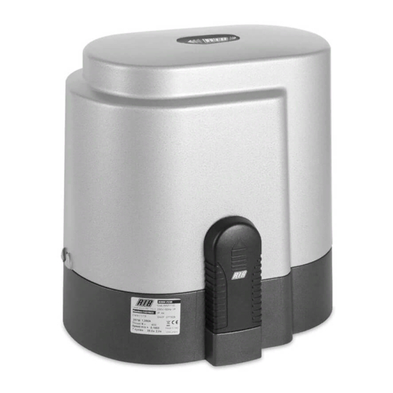
K400
6,41"
12,16"
Misure in mm/inch - Mesures en mm/inch - Measurements in mm/inch - Abmessungen in mm/inch
GB
1° - This instruction booklet is exclusively dedicated to specialized staff who are aware of
the construction criteria and of the accident prevention protection devices for motorized
gates and doors (according to the current regulations and laws).
2° - Keep the automatic control (push-button, remote control, etc) out of the reach of children.
The control systems must be installed at a minimum hight of 1.5m from the ground surface
and not interfere with the mobile parts.
3° - Before starting any installation and operation or maintenance work make sure to cut off
power supply by turning the general magnetothermic switch off.
WARNING - INCORRECT INSTALLATION CAN LEAD TO SEVERE INJURY
R.I.B. IS NOT LIABLE for any damage caused by not following the safety regulations and laws at
present in force not being observed during installation.
D
1° - Diese Montageanweisung ist ausschließlich für geschultes Fachpersonal bestimmt,
das mit den Montagevorschriften und den Schutzvorrichtungen zur Verhinderung von
Unfällen bei motorisierten Toren vertraut ist (nach den aktuellen Normen und Gesetzen).
2° - Bewahren Sie die Geräte für die automatische Bedienung (Drucktaster, Funksender, u.s.w.)
an einem für Kinder unzugänglichen Platz auf. Die Steuerungen müssen auf einer
Mindesthöhe von 1,5 m angebracht werden und sich ausserhalb der Raumes der
bewegenden Teile befinden.
3° - Bevor Sie eine Installation oder Wartungsarbeit an der Anlage durchführen, müssen Sie
kontrollieren, dass die Anlage spannungsfrei geschaltet ist.
ACHTUNG - EINE FALSCHE INSTALLATION KANN ZU BEDEUTENDEN SHÄDEN FÜHREN
R.I.B. HAFTET NICHT für eventuelle Schäden, die bei der Installation durch Nichtbeachtung der
jeweils gültigen Sicherheitsvorschriften entstehen.
IMPORTANT SAFETY INSTRUCTIONS
WARNING - IT IS IMPORTANT FOR THE SAFETY OF PERSONS
TO FOLLOW ALL INSTRUCTIONS
SAVE THESE INSTRUCTIONS
WICHTIGE ANWEISUNGEN FÜR DIE SICHERHEIT
ACHTUNG - UM DIE SICHERHEIT VON PERSONEN VOLLKOMMEN
GARANTIEREN ZU KöNNEN, IST ES WICHTIG, DASS ALLE
INSTALLATIONSVORSCHRIFTEN BEACHTET WERDEN
Pag. 1 di 28
I
F
GB
D
11,7"
Advertisement

Subscribe to Our Youtube Channel
Related Manuals for RIB K400 PLUS 12V


Summary of Contents for RIB K400 PLUS 12V
- Page 1 ATTENZIONE - UNA SCORRETTA INSTALLAZIONE PUÓ PORTARE A DANNI RILEVANTI R.I.B. IS NOT LIABLE for any damage caused by not following the safety regulations and laws at LA DITTA RIB NON ACCETTA NESSUNA RESPONSABILITÀ per eventuali danni provocati present in force not being observed during installation.
- Page 2 Power Supply with Encoder Max gate weight Thrust K Max Thrust code Torantrieb Stromspannung mit Encoder Max Torgewicht Schubkraft Max Schubkraft codice K400 PLUS 12V 230V 50/60Hz 400Kg / 890lbs 11Kg/25lbs 11Kg/25lbs AA20016 “ 120V 60Hz “ “ “ AA20052...
- Page 3 Pag. 3 di 28 LAY-OUT IMPIANTO 1 - Operatore K 2 - Fotocellule esterne 3 - Cremagliera Modulo 4 4 - Selettore a chiave 5 - Antenna radio 6 - Lampeggiatore 7 - Limitatori di corsa (camme) 8 - Costola meccanica 9 - Costola pneumatica o Fotocosta 10 - Fotocellule interne 11 - Colonnine per fotocellule...
- Page 4 Pag. 4 di 28 Misure in mm 2 - FISSAGGIO MOTORE E CREMAGLIERA (Fig.5-6) La cremagliera va fissata a una certa altezza rispetto all’appoggio del motore. Questa altezza può essere variata grazie a delle asole presenti sulla cremagliera. La registrazione in altezza viene fatta affinché il cancello durante il movimento non si appoggi sull'ingranaggio di trazione del K (Fig.
- Page 5 (onnipolare con apertura minima dei contatti pari a 3mm) che riporti un marchio di conformità alle normative internazionali. 2° - Per la sezione ed il tipo dei cavi la RIB consiglia di utilizzare un cavo di tipo NPI07VVF con sezione minima di 1,5mm e comunque di attenersi alla norma IEC 364 e alle norme di installazione vigenti nel proprio Paese.
- Page 6 Pag. 6 di 28 5 - CONTROLLO SENSO DI ROTAZIONE DEL MOTORE minuti ed il lampeggiatore sarà attivo per un minuto. Durante o dopo i 5 minuti di allarme suoneria (buzzer), è possibile ristabilire il Questo controllo ha il compito di agevolare l’installatore durante la messa in opera funzionamento del cancello premendo un qualsiasi pulsante di comando.
- Page 7 Pag. 7 di 28 => Contatto Fotocellula 2 (NC) => Comando apertura pedonale (NO) => Contatto libero => Comune EXPANDER 12V SEGNALAZIONI LED SCHEDA segnalazione contatto fotocellula 2 segnalazione contatto pedonale ALIMENTAZIONE SPIA DI SEGNALAZIONE STATO BATTERIA libero In caso di mancanza di tensione di rete con intervento della batteria di emergenza, questa Presenza tensione spia si accende segnalando la mancanza di rete, e comincia a lampeggiare solo quando la N.B.: Per un corretto funzionamento i LED D2 e D5 devono essere sempre accesi.
- Page 8 Pag. 8 di 28 ANTENNAANTENNA SPARK FOTOCELLULE FIT SYNCRO DA PARETE - cod:ACG8026 Per ottenere le migliori prestazioni degli apparati sopracitati, bisogna installare Portata settabile 15÷30mt un’antenna accordata sulla frequenza del radio ricevitore installato . Sono applicabili più coppie ravvicinate tra loro grazie al circuito sincronizzatore. N.B.
- Page 9 Pag. 9 di 28 SCHÉMA DÉTAILLÉ DE 1 - Opérateur K L'INSTALLATION 2 - Photocellules extérieures 3 - Crémaillère Module 4 4 - Sélecteur à clé Ç 5 - Antenne radio 6 - Feu clignotant 7 - Limiteurs de course (cames) 8 - Nervure mécanique 9 - Nervure pneumatique ou "Photonervure"...
- Page 10 Pag. 10 di 28 Misure in mm 2 - FIXATION MOTEUR ET CRÉMAILLÈRE (Fig.5-6) La crémaillère doit être fixée à une certaine hauteur par rapport au support du moteur. Cette hauteur peut être modifiée, grâce aux boutonnières présentes sur la crémaillère. Le réglage en hauteur est effectué...
- Page 11 à 3mm); la marque de cet interrupteur devra être en conformité avec les normes internationales. 2° - En ce qui concerne la section et le type des câbles, le conseil de la RIB est celui d'utiliser un câble de type NPI07VVF présentant une section minimale de 1,5mm quoi qu'il en soit, de se conformer à...
- Page 12 Pag. 12 di 28 5 – CONTRÔLE DU SENS DE ROTATION DU MOTEUR Pendant ou après les 5 minutes d'alarme sonnerie (buzzer), il est possible de rétablir le fonctionnement du portail en appuyant sur l'un des boutons de commande (n'importe Ce contrôle a pour but de rendre plus aisée la tâche de l’installateur, lors de la mise en lequel).
- Page 13 Pag. 13 di 28 => Contact photocellule 2 (NC) => Commande ouverture piétonne (NO) => Contact libre => Mise à terre Ç EXPANDER 12V SIGNALISATIONS VOYANTS LUMINEUX CARTE signalisation contact photocellule 2 signalisation contact piétonnier ALIMENTATION VOYANT DE SIGNALISATION ÉTAT BATTERIE libre Présence de tension En cas de manque de tension de réseau avec intervention de la batterie de secours, ce voyant...
- Page 14 Pag. 14 di 28 ANTENNE SPARK PHOTOCELLULES MURALES FITSYNCRO - code ACG8026 Afin d'optimaliser les performances des appareils suscités, il est indispensable d'installer Portée cloisonnable 15÷30mt une antenne accordée sur la fréquence du radiorécepteur installé. Plusieurs couples sont appliqués, rapprochés les uns des autres grâce au circuit N.B.
- Page 15 Pag. 15 di 28 SYSTEM LAY-OUT 1 - K operating device 2 - External photocells 3 - Rack of Module 4 4 - Key selector 5 - Radio antenna 6 - Blinker 7 - Travel limiting devices (cams) 8 - Mechanical strip 9 - Pneumatic strip or Fotocosta 10 - Internal Photocells 11 - Photocell posts...
- Page 16 Pag. 16 di 28 Misure in mm/inches 6,6” 2 - MOTOR AND RACK FITTING (Fig.5-6) The rack shall be fitted over the motor support, at a certain distance from It. Its height can be adjusted thanks to the holes In the rack. The height is adjusted to prevent the gate from resting on the driving gear of the K as it moves (Fig.
- Page 17 2° - As far as the cable section and the cable kind are concerned, RIB suggests to use an NPI07VVF cable, with a minimum section of 1,5mm2, and to follow, In any case, the IEC 364 standard and Installation regulations In force In your Country.
- Page 18 Pag. 18 di 28 5 – CONTROL OF THE MOTOR ROTATION DIRECTION gate stops and than reverses Its movement for 1 second. The buzzer is operated to signal the alarm 5 minutes long and the blinker blinks one minute long. This control is carried out to facilitate the installation of the system or any possible future During and after the 5 minutes when the buzzer alarms, you can make the gate work control.
- Page 19 Pag. 19 di 28 => Photocell 2 (NC) contact => Pedestrian opening command (NO) => Free contact => Common unit EXPANDER 12V CARD LED SIGNALS Photocell 2 contact signal WARNING LIGHT FOR THE BATTERY STATE Pedestrian contact signal Free In case of network voltage drop, with safety battery activation, this warning light turns on, Voltage presence signalling the power mains failure, and starts blinking only when the battery is charged.
- Page 20 Pag. 20 di 28 SPARK ANTENNA FITSYNCRO PHOTOCELLS for the wall-installation - code:ACG8026 In order to make the systems mentioned above give the best performances, you need to The range you can set is 15÷30mt - 49÷100” install an antenna tuned on the frequency of the radio receiver installed. You can fit many couples close together thanks to the synchronising circuit.
- Page 21 Pag. 21 di 28 ANLAGEN LAY-OUT 1 - Betriebsgerät K 2 - Externe Fotozellen 3 - Zahnstange Modul 4 4 - Schlüsselwählschalter 5 - Radioantenne 6 - Blinkleuchte 7 - Laufbegrenzer (Nocken) 8 - Mechanische Kontaktleisten 9 - Pneumatische Kontaktleisten oder Fotokontaktleiste 10 - Interne Fotozellen 11 - Standsäulen für Fotozellen...
- Page 22 Pag. 22 di 28 Abmessungen in mm 2 – MOTORBEFESTIGUNG UND ZAHNSTANGE (Abb. 5-6) Die Zahnstange muss gegenüber der Motorhalterung in einer entsprechendenden Höhe befestigt werden. Diese Höhe kann mittels an der Zahnstange befestigten Ösen verändert werden. Die Höhenregulierung muss solange erfolgen, bis das Tor sich während der Bewegung nicht mehr auf das Zugrad K aufstützt (Abb.
- Page 23 Kontaktöffnung von 3 mm), der ein von den internationalen Normen anerkanntes Konformitätszeichen besitzt. 2. – RIB empfiehlt den Kabeltyp NPI07VVF mit einem minimalen Querschnitt von 1,5mm generell sollten die Normative IEC 364 und alle anderen geltenden Montagenormen des Bestimmungslandes eingehalten werden.
- Page 24 Pag. 24 di 28 5 – KONTROLLE DER ROTATIONSSINN DES MOTORS Es ist während oder nach den 5 Minuten, in denen das Läutwerk (Buzzer) aktiv ist, möglich, den Betrieb des Tors durch die Betätigung einer beliebigen Steuertaste erneut zu Diese Kontrolle dient der Erleichterung der Installation während der Inbetriebnahme der stabilisieren.
- Page 25 Pag. 25 di 28 => Kontakt Fotozelle 2 (NC) => Befehl Öffnen Personenöffnung (NO) => Leerkontakt => Allgemeine Einheit LED-ANZEIGEN FÜR DIE EXPANDERKARTE 12V Anzeige Kontakt Fotozelle 2 Anzeige Kontakt Personenöffnung STROMVERSORGUNG DER BATTERIESTATUS-KONTROLLLEUCHTE Frei Diese Kontrollleuchte schaltet sich ein, wenn keine Netzspannung vorhanden ist und die Spannung vorhanden Notbatterie einsetzt.
- Page 26 Pag. 26 di 28 WANDFOTOZELLEN FITSYNCRO - Kennnr.:ACG8026 ANTENNE einstellbare Reichweite 15÷30mt 49÷100” Um die bestmöglichen Leistungen mit den o. g. Apparaten zu erhalten, muss eine auf die Dank einer Synchronisiereinrichtung sind mehrere sich gegenseitig annähernde Paare Frequenz des Funkempfängers abgestimmte Antenne montiert werden. möglich.
- Page 27 RIB e scaricabile all'indirizzo internet http://www.ribind.it/exe/ribtec.exe - Pour la redaction du présente notice technique d'installation a été rédigée dans le respect de la Directive Machines 89/392. Les formulaires RIB sont à la disposition de l'utilisateur, ils peuvent être déchargés depuis le site http://www.ribind.it/exe/ribtecfr.exe - For the editing of the technical installation brochure in compliance with the Machine Directive 89/392, the installer can avail himself of the forms prepared by RIB, that can also be downloaded from the internet address: http//www.ribind.it/exe/ribtecen.exe...
- Page 28 Pag. 28 di 28 K400-12V Codice Denominazione Particolare Codice Denominazione Particolare Codice Denominazione Particolare ACG9510 Batteria 12V CME2082 Perno di sblocco CTC1123 Seeger E25 BA01019 Serie accessori per cilindro CME3066 Flangia anteriore motore CTC1152 Spina elastica 3x30 BC00189 Circuito forcellino ottico K CMO2600 Gruppo motore CTC1164...
Need help?
Do you have a question about the K400 PLUS 12V and is the answer not in the manual?
Questions and answers