
Related Manuals for SunSynk LIFELYNK X SM3.6kWLL


Summary of Contents for SunSynk LIFELYNK X SM3.6kWLL
- Page 1 SM3.6kWLL LIFELYNK MOBILE USER MANUAL www.sunsynkmobile.com / sales@sunsynkmobile.com Please retain for 1223 future reference...
- Page 2 Index Safety 1.1. General Safety Information 1.2. Symbols in the Manual Symbols in the Product 1.4. Safety Instructions 1.5. Disposal Product Introduction Box Contents Technical Specification Installation 5.1. Selecting the Mounting Area 5.2. Mounting the Inverter 5.3. Turning on the Batteries 5.4.
- Page 3 Operation 8.1. System Flow 8.2. Switching On / Off 8.3. Home Screen 8.4. Home Settings 8.5. Basic Settings 8.6. Work Mode Settings 8.7. System Logger 8.8. Advance Settings 8.8.1. Grid Settings 8.8.2. Battery Settings 8.8.3. System Settings 8.8.4. Export Control 8.8.5.
-
Page 4: General Safety Information
1. SAFETY 1.1. General Safety Information This device should only be used in accordance with the instructions within this manual and in ƒ compliance with local, regional and national laws and regulations. Only allow this device to be installed, operated, maintained or repaired by other person(s) who have also read and understood this manual. - Page 5 1.3. Symbols in the Product Caution, risk of electric shock. Caution, risk of burn. Be careful when touching the inverter! It is an electrical product with risk of electric shock and heating. Indicates that this product is recyclable. Indicates that the device, accessories and packaging must not be disposed of as unsorted municipal waste and must be collected separately at the end of the usage.
-
Page 6: Safety Instructions
1.4. Safety Instructions WARNING HIGH LIFE RISK DUE TO FIRE OR ELECTROCUTION. The Lifelynk X can only be installed by a qualified licensed electrical contractor. This is not a DIY product. Ensure to follow the safety warnings listed below: Be sure to read this manual thoroughly before installation. ƒ Do not attempt to install the inverter by yourself. Installation work must be carried out in compliance ƒ... -
Page 7: Product Introduction
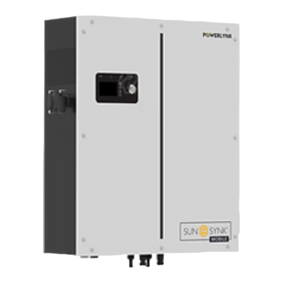
2. PRODUCT INTRODUCTION The Lifelynk X is a highly efficient power management tool that allows the user to hit those ‘parity’ targets by managing power-flow from multiple sources such as solar, mains power (grid) and generators, and then effectively storing and releasing power as and when utilities require. INTERACTIVE Easy and simple to understand LCD display. -
Page 8: Box Contents
This box contains: Lifelynk X (main unit) Wall mounting bracket Screw pack Data logger (Sunsynk Wi-Fi) CT Coil (2 pin AERO type female connector) 3m cable 1x3 pin AC Load connector (female) and 1x3 pin AC 2 x MC4 connectors Grid connector (male) 4. TECHNICAL SPECIFICATION... - Page 9 Model Lifelynk X PV Input Data Max. PV Power 4500W Max. PV Input Voltage 500V MPPT Voltage Range 120-450V Start-up Voltage 150V Max. PV Current 12A (total current of the two MC4 sets combined) AC Output / Input Data Maximum Input Power 3600W Nominal Input / Output Power 3600W...
-
Page 10: Installation
5. INSTALLATION 5.1. Selecting the Mounting Area MOBILE DO NOT install in the following areas: Areas with high salt content, such as the marine environment. It will deteriorate the metal parts and ƒ possibly lead to water / dampness penetrating the unit. Areas filled with mineral oil or containing splashed oil or steam such as in kitchens. -
Page 11: Mounting The Inverter
ALSO CONSIDER: Installing the indoor unit, outdoor unit, power supply cable, transmission cable and remote control cable ƒ at least 1 metre away from any television or radio receiver. This will prevent TV reception interference or radio noise. This will also prevent radio signal interference from external units that might interfere with the Wi-Fi or GSM monitoring. - Page 12 CAUTION Risk of Injury (Heavy Object) Remember that this inverter is heavy, so users must be careful in handling the unit during installation especially when mounting or removing from a wall. 5.3. Turning on the Batteries Turn the battery isolation switch to turn on the batteries.
-
Page 13: Flow Diagram
5.4. Flow Diagram Essential Loads Non-Essential Loads 5.5. Connecting to the Mains / Grid 1. Connect the Lifelynk X Hybrid Inverter to the electrical grid via the grid ports, using a suitable RCD and a 20A fuse on the consumer board. 2. Now, using a 3mm cable, connect only the essential loads to the load ports (output) to a secondary consumer board, considering the maximum limit of 3.6 kW. - Page 14 5.7. CT Coil and Load Power Settings The CT coil is one of the most important parts of the Lifelynk X. This device reduces the power of the inverter to prevent feeding power to the grid. This is also known as zero export. Fit the coil (sensor) around the live cable on the main fuse feeding the building and run the cable back to ƒ...
-
Page 15: Internal Battery Pack
You can access the CT Coil Screen directly from the Home Screen by pressing the Home/Back button: CT Power Load Power Work Mode: Standalone Input Trickle Feed: 30W Export Control: Zero Export Earth Neutral Bond: Enable Night Power Saving: Enable You can access the Internal Battery Pack page by pressing the Home/Back button again: Internal Battery Pack Capacity: 75Ah... -
Page 16: Parallel Operation
5.8. Parallel Operation In order to connect Lifelynk inverters to operate in parallel, you need to set up the work mode configuration for each the inverter. Basically, you have to set which inverter will be the master and which will be the slaves, and then make the connections described in section 5.9 (External Battery and Parallel Connections). - Page 17 5.9. External Battery and Parallel Connections Inverter Unit: 1 External Battery Number: 1 Inverter Unit: 1 External Battery Number: 2 Inverter Unit: 2 External Battery Number: 1 Inverter Unit: 2 External Battery Number: 2 Inverter Unit: 3 External Battery Number: 1 SM3.6kWLL - Lifelynk X...
- Page 18 Inverter Unit: 3 External Battery Number: 2 Inverter Unit: 2 External Battery Number: 1 (Shows CT Coil Connection + Master&Slave) Inverter Unit: 2 External Battery Number: 2 (Shows Batteris connected in parallel) Inverter Unit: 3 External Battery Number: 6 (Show External Batteries can be installed into each inverter) SM3.6kWLL - Lifelynk X...
-
Page 19: Lcd Display Screen
6. LCD DISPLAY SCREEN The LCD display screen is situated on the front of the Lifelynk X, this is where you can control and operate the system. 1. Power - to turn the system on / off. 2. Settings / Select - to operate the settings menu &... -
Page 20: Factory Settings
7. FACTORY SETTINGS Battery Settings Default Setting Low Battery Cut Off 45.0V Reboot Voltage 50.0V Maximum Charge Charge from MAIN Float Charge Voltage 56.0V Active System Configuration Default Setting Maximum Discharge Current Maximum Battery Voltage 56.0V Import Trickle Feed 0030W Export Control Zero Export Earth Neutral Bond Enable... -
Page 21: Operation
8. OPERATION 8.1. System Flow Solar Power/Voltage Inverter Power/Voltage 185W/ 188W/ 187V 240V Battery Voltage Gen Voltage/Freqence 52.7V 240V/ 52.0Hz System Mode / Current DATE: 17-07-2021 Chg/ TIME: 11:33:25 0.8A Temp 23.6C Home Settings Basic System Logger System Logger Basic Settings Fault Codes Advanced Set Time 15:16... -
Page 22: Switching On/Off
What you can do from this page If you press the select button you can navigate to the basic setup menu If Sunsynk Connect has been connected, the WI-FI icon apppears Access the CT screen by pressing the Home/Back button... -
Page 23: Home Settings
8.4. Home Settings Home Settings Basic System Logger Fault Codes Advanced What does this page display? Basic setting icon System logger icon Fault codes icon Advanced settings icon What you can do from this page You can navigate through the functions by clicking on each icon 8.5. Basic Settings Basic Settings Basic Settings... - Page 24 What you can do from this page Set the system’s time Set the system’s date Set backlight Set the workmode Set the system SOC/Voltage Reset to factory default settings After changing the settings, do not forget to click save settings. Basic Settings Save Settings? 8.6. Work Mode Settings...
- Page 25 Then, the “Work Mode Settings” page will display. Work Mode Settings Standalone Single-Phase Master Single-Phase Slave What does this page display? The Work Mode selected Single-Phase Master Single-Phase Slave number What you can do from this page Change the number of Slave Inverters (maximum 15 slaves) 8.7. System Logger System Logger Solar Production...
-
Page 26: Advance Setting
What you can do from this page Daily solar power produced Monthly solar power produced Yearly solar power produced Total solar power produced Daily grid power used Monthly grid power used Yearly grid power used Total grid power produced 8.8. Advance Settings Advance Setting Grid Settings Battery Settings... -
Page 27: Grid Settings
8.8.2. Grid Settings Grid Settings Grid Mode G98/G99 Max Grid Volt 253V Min Grid Volt 195.5V Min Grid Freq 47.5Hz Max Grid Freq 52.0Hz Voltage AC 230V Frequency 50Hz What does this page display? Grid Mode Maximum grid voltage allowed Minimum grid voltage allowed Maximum grid frequency Minimum grid frequency 8.8.1. Battery Settings... -
Page 28: System Settings
What you can do from this page Set a low voltage cut-off for the batteries. Before setting this, please refer to the battery characteristics. The reboot voltage is the voltage that the batteries must reach before the inverter switches on again. Maximum charge is the maximum current that the system will provide to charge the batteries. -
Page 29: System Config
8.8.4. Export Control The Export Control can be set as “UPS” and “Zero Export”. 1. “UPS” When the “Export Control” is set to “UPS”, the inverter will not export power to the home load via the “GRID” connector, just power the essential load that is connected to the “LOAD” connector. When the “Charge from Main”... - Page 30 8.8.7. Night Power Saving The Night Power Saving can be set to “Enable” or “Disable”. When is set to “Enable”, the Night Power Sav- ing function will be available. When it is set to “Disable”, this function will not be available. PLEASE NOTE ”Night Power Saving”...
-
Page 31: Setting Details
8.9. Setting Details 1. UPS Mode This mode function is set, the inverter output is from the load only and will not export any power to the GRID even if it is connected. Set the Charge from AC by “Yes” and Export Control set by “UPS”. Battery Settings System Config Low Battery Cut Off... - Page 32 2. Zero Export Mode This mode function allows the inverter to export power to the home load via the “GRID” connector and power the essential load connected to the “LOAD” connector simultaneously. When zero export is ON, the inverter will export energy to the grid. The maximum power will not exceed the total load power of the grid. Battery Settings System Config Low Battery Cut Off...
- Page 33 3. Night Power Saving When there is no PV, and the battery is not charged from AC, the output power will be to the load from the battery. When the battery level is equal to the battery set in the system control in that time period, and it is set to Y, then the inverter will run at a low power level from GRID to maintain the battery level is not dropped to shut down the inverter.
-
Page 34: Fault Codes
Error Code Description Solutions Working mode change Inverter work mode changed: 1. Reset the inverter. 2. Seek help from Sunsynk Mobile. Short circuit protecting Short circuit fault: 1. Maintain the connection. 2. Proceed to the settings to modify the work mode. - Page 35 ON status, it will disappear automatically; 3. If the fault exists, please contact us for help. Load current exceeding 1. Try tu reduce the load power. 2. Seek help from Sunsynk Mobile. No AC grid 1. Check if the inverter’s connected to the AC grid.
-
Page 36: Startup / Shutdown Procedure
Error Code Description Solutions Bus one shutdown 1. Reset the inverter. 2. Seek help from Sunsynk Mobile. FAN Error 1. A technician needs to check the internal fan wire or replace fan. 2. Seek help from Sunsynk Mobile. Heat sink high-temperature failure Heat sink temperature is too high: 1. - Page 37 Check the earth bond on the Check the Voc does not Ensure both MPPTs are solar panels. exceed 450V. balanced. Measure the supply voltage, If it falls out of the setting See grid set up page. check it matches the settings range it will cause the of the inverter.
-
Page 38: Gfdi Fault
2. Be of the type specified in the inverter manufacturer’s instructions or as labelled on the inverter. We recommend the use of an RCD on all circuits and sub circuits connected to the Sunsynk Mobile inverter. Residual current breaker with overcurrent protection (RCBO). - Page 39 MOBILE Email Us: Website: sales@sunsynkmobile.com www.sunsynkmobile.com VAT Number: 175669460 Address UK: Sunsynk UK Ltd. 17 Turnstone Business Park, Mulberry Avenue, Widnes, Cheshire, WA8 0WN Call Us UK: +44 151 832 4300...
Need help?
Do you have a question about the LIFELYNK X SM3.6kWLL and is the answer not in the manual?
Questions and answers