Advertisement
Quick Links
Section 1,
"Introduction"
Section 2, "Functional Blocks
Section 3, "Configuration and Connections
Section 4, "Additional
Info"
Section 5, "Revision
History"
Freescale Semiconductor
Symphony SoundBite
Contents
page 2
page 3
page 5
page 12
page 12
Symphony SoundBite Reference Manual, Rev. 2.0
Reference Manual
Document Number: SNDBITERM
Rev. 2.0
09/2008
1
Advertisement

Subscribe to Our Youtube Channel
Related Manuals for NXP Semiconductors Symphony SoundBite


Summary of Contents for NXP Semiconductors Symphony SoundBite
- Page 1 09/2008 Contents Section 1, “Introduction” page 2 Section 2, “Functional Blocks page 3 Section 3, “Configuration and Connections page 5 Section 4, “Additional Info” page 12 Section 5, “Revision History” page 12 Symphony SoundBite Reference Manual, Rev. 2.0 Freescale Semiconductor...
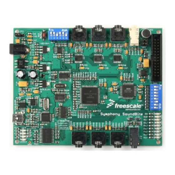
- Page 2 Introduction Introduction The Symphony SoundBite is a versatile audio application development board built upon the DSPB56371 Digital Signal Processor. The Symphony SoundBite costs very little and is ideal for cost-sensitive organizations, like university digital signal processing labs, small engineering companies, and even the frugal hobbyist.
-
Page 3: Functional Blocks
AK4584 codec) — Capable of being powered via SLK header — Power supply selected by a single jumper and indicated by an LED Functional Blocks The Symphony SoundBite development board consists of 4 functional blocks: Audio Debug/Com •... - Page 4 C serial EEPROM (U6), connected to the DSP through positions 5 and 6 of SW2, provides non-volatile data storage and allows the Symphony SoundBite to boot up and run application software in a stand-alone configuration (without a PC connected to download code). Audio data in I S format is transmitted through the DSP's ESAI port and received via the DSP's ESAI_1 port.
- Page 5 The external supply can be 6–9 VAC or 9–12 VDC with a current capacity of at least 400 mA. When USB powering is selected, the Symphony SoundBite board remains unpowered until the FT2232 is enumerated with the PC host. When this occurs, the FT2232 (U7) PWREN# signal is asserted low, applying 5V from the USB port through the the current limiting switch TPS2021 (U15) to the 3.3V and 1.25V regulators.
-
Page 6: System Reset
The power source for the Symphony SoundBite board is selected using the JP3 jumper. See Table Table 1. JP3 Jumper Selects Power Source Jumper Selects external power, supplied through PWR_JACK. - Page 7 The default state for SW2 is 110110 (SW2 positions 6:1), which sets Boot Mode 9 and enables the I EEPROM (allowing stand-alone operations). As shipped from Freescale, the I C EEPROM contains the Symphony SoundBite demonstration application program, which is documented separately in the Symphony SoundBite documentation. Audio Input/Output Jacks: J1–J8 Jacks J1, J3, J5, and J7 accept line-level analog inputs and jacks J2, J4, J6, and J8 provide line-level outputs.
- Page 8 DSP GPIO pin that corresponds to each LED identifier. Table 4. General Purpose LEDs Color Schematic DSP Pin Green GPLED0 Green GPLED1 Green GPLED2 Green GPLED3 PF10 Amber GPLED4 TIO0/PB0 Amber GPLED5 TIO1/PB1 GPLED6 GPLED7 GPLED8 Symphony SoundBite Reference Manual, Rev. 2.0 Freescale Semiconductor...
- Page 9 There are no provisions for disconnecting the LEDs from the GPLEDx lines. Additionally, you can modify the Symphony SoundBite board by soldering jumpers between the 4 solder pads at CON1 to any of the 4 IRQ lines, IRQD:A, the I C lines SDA and SCL, and GPIO pin PC7, as desired.
- Page 10 The microphone preamplifier output is connected to both channels of J1 through Stereo Output 0 jumper JP1. Stereo Input 1 Analog only. Stereo Output 1 Stereo Input 2 Analog only. Stereo Output 2 Stereo Input 3 Analog only. Stereo Output 3 Analog only. Symphony SoundBite Reference Manual, Rev. 2.0 Freescale Semiconductor...
- Page 11 General purpose switches (8x), can be programmed by DSP applications. Mode Select DSP boot mode select and EEPROM enable Board Reset Momentary switch, resets the Symphony SoundBite board. Jumper Microphone Select Route Microphone output to Left or Right Channel Power Source Select 3 pins.
- Page 12 Additional Info Additional Info For additional information, please refer to the Symphony SoundBite Documentation Overview document, which provides an overview of all the documentation relevant to the programming and usage of the Symphony SoundBite audio development board. Symphony SoundBite Reference Manual, Rev. 2.0...
Need help?
Do you have a question about the Symphony SoundBite and is the answer not in the manual?
Questions and answers