Advertisement
Quick Links
www.ti.com
EVM User's Guide: XWRL1432BOOST
Low Power 77 GHz mm-Wave Sensor
Description
The xWRL1432BOOST from Texas Instruments is
an easy-to-use evaluation board for the xWRL1432
mmWave sensing device, with standalone operation
and direct connectivity to the DCA1000EVM for raw
ADC capture and signal processing development.
This EVM contains everything required to start
developing software for on-chip Hardware accelerator
and low power ARM
®
Cortex
Get Started
1. Visit xWRL1432BOOST EVM product page.
Automotive - AWRL1432BOOST.
Industrial - IWRL1432BOOST.
2. Configure the SOP Switches (S1 and S4), for
functional mode(SOP4).
3. Visit TI Developer Zone for essential software like
SDK and Radar Toolbox.
Automotive - AWRL1432BOOST.
Industrial - IWRL1432BOOST.
4. Navigate to the Radar Toolbox.
5. The user's guide is located here:
SWRU613 – JULY 2023
Submit Document Feedback
®
- M4F controllers.
XWRL1432BOOST EVM
Copyright © 2023 Texas Instruments Incorporated
Radar Toolbox\Example Projects\Out of Box
Demo\xWRL1432 Out of Box Demo\.
6. Further explore the Radar Toolbox for more
information, applications, and resources.
Features
•
High RF Performance RO4835LoPro PCB
substrate
•
Wide field of view antenna, targeted for wall mount
applications
•
XDS110 JTAG interface with USB connectivity for
code development and debugging
•
Power optimized discrete DCDC power
management
•
Serial port for onboard QSPI flash programming
•
60-pin, high-density (HD) connectors for raw
analog-to-digital converter (ADC) data
•
Onboard CAN-FD transceiver
•
Onboard LIN PHY transceiver for automotive
variant.
•
USB powered standalone mode of operation
•
EVM is designed as booster pack to connect with
other LaunchPad EVMs
•
On board 16Mbit QSPI flash
Low Power 77 GHz mm-Wave Sensor
Description
1
Advertisement

Related Manuals for Texas Instruments XWRL1432BOOST


Summary of Contents for Texas Instruments XWRL1432BOOST
- Page 1 Low Power 77 GHz mm-Wave Sensor Radar Toolbox\Example Projects\Out of Box Description Demo\xWRL1432 Out of Box Demo\. The xWRL1432BOOST from Texas Instruments is 6. Further explore the Radar Toolbox for more an easy-to-use evaluation board for the xWRL1432 information, applications, and resources.
-
Page 2: Kit Contents
Automotive and Industrial space of applications. The xWRL1432BOOST EVM enables access to point-cloud data and power over USB interface. The xWRL1432BOOST supports direct connectivity to the DCA1000EVM development kit. This kit is supported by mmWave tools, demos and software including mmWave software development kit (MMWAVE-L-SDK) and TI's Code Composer Studio. -
Page 3: Device Information
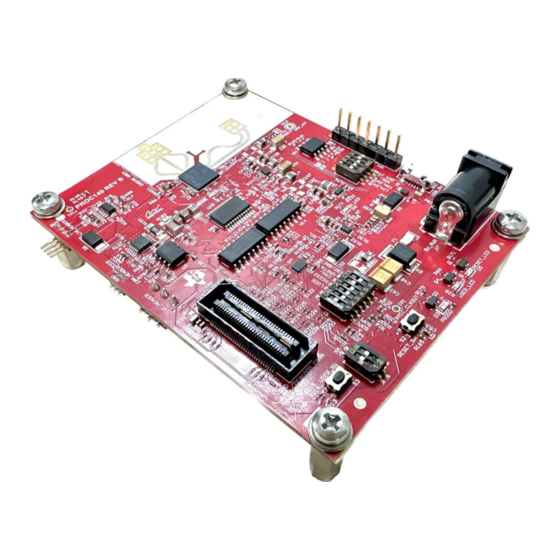
Texas Instruments integrated circuits used in the assembly of the xWRL1432BOOST EVM. This user's guide is available from the TI web site under literature number SWRU613. Any letter appended to the literature number corresponds to the document revision that is current at the time of the writing of this document. - Page 4 Hot surface. Contact can cause burns Do not touch. The XWRL1432BOOST includes three receivers and two transmitters with a wide field of view hosted on a High RF Performance RO4835LoPRO PCB substrate. Figure 2-1. XWRL1432BOOST (Top View) Low Power 77 GHz mm-Wave Sensor SWRU613 –...
- Page 5 Hardware Figure 2-2. XWRL1432BOOST (Bottom View) Figure 2-3. Salient Features of EVM (Top Side) SWRU613 – JULY 2023 Low Power 77 GHz mm-Wave Sensor Submit Document Feedback Copyright © 2023 Texas Instruments Incorporated...
- Page 6 Figure 2-4. Salient Features of EVM (Bottom Side) 2.1 XWRL1432BOOST Antenna The XWRL1432BOOST includes three receivers and two transmitters FR4 based antennas on the PCB. Figure shows the antenna configuration. Figure 2-5. TX and Rx Antennas of the EVM Low Power 77 GHz mm-Wave Sensor SWRU613 –...
- Page 7 Hardware Note The XWRL1432BOOST has an antenna gain of approximately 5-6 dBi across different antenna pairs. 2.1.1 PCB Material Material used for this PCB is Rogers RO4835LoPro of 4mil thickness with rolled copper for the Antenna and transmission lines and 370HR is used for the rest of the layers.
- Page 8 Thus, for the -6dB beam width, the user must see a -12db (Tx (-6dB) + Rx(-6dB)) number from the boresight. Note Wavelength (Lambda) is computed based on a frequency of 78.5 GHz. Antenna placements are according to this frequency. Low Power 77 GHz mm-Wave Sensor SWRU613 – JULY 2023 Submit Document Feedback Copyright © 2023 Texas Instruments Incorporated...
- Page 9 Hardware Figure 2-7. xWRL1432BOOST EVM Azimuth Antenna Radiation Patterns Measured azimuthal radiation pattern for all Tx to Rx pairs (Corner reflector placed at approximately 5 meters with a 4- GHz bandwidth chirp starting at 76 GHz) SWRU613 – JULY 2023...
- Page 10 Hardware www.ti.com Figure 2-8. xWRL1432BOOST EVM Elevation Antenna Radiation Patterns Measured elevation radiation pattern for all TX to RX pairs (Corner reflector placed at approximately 5 meters with a 4-GHz bandwidth chirp starting at 76 GHz) Note In accordance to the EN 62311 RF exposure test, a minimum separation distance of 20 centimeters must be maintained between the user and the EVM during operation.
-
Page 11: Switch Settings
Figure 2-9. Muxing Options for the EVM 2.3 Switch Settings Figure 2-10 shows the part designators and positions of the switches (S1 and S4) on the XWRL1432BOOST. Figure 2-10. S1 Switch for Various Mode Settings SWRU613 – JULY 2023 Low Power 77 GHz mm-Wave Sensor Submit Document Feedback Copyright ©... - Page 12 Figure 2-12 also provides the switch position for different modes of operation supported by the device and EVM. Figure 2-12. SOP Switches Low Power 77 GHz mm-Wave Sensor SWRU613 – JULY 2023 Submit Document Feedback Copyright © 2023 Texas Instruments Incorporated...
-
Page 13: Usb Connector
Hardware 2.4 LEDs Table 2-1 contains the list of LEDs on the XWRL1432BOOST. Table 2-1. List of LEDs LED reference designators Description 5 V Power indication Reset LED. NERROR LED Note: There is switch settings are needed to enable this. - Page 14 (SPI, UART, I2C, NRST, NERROR, and SOPs) to the DCA1000. Figure 2-14. DCA1000 HD Connector Low Power 77 GHz mm-Wave Sensor SWRU613 – JULY 2023 Submit Document Feedback Copyright © 2023 Texas Instruments Incorporated...
- Page 15 J8/J9 are the booster pack connectors provided for the connectivity option with the other TI LaunchPad ecosystem. Figure 2-15. Booster Pack Connector SWRU613 – JULY 2023 Low Power 77 GHz mm-Wave Sensor Submit Document Feedback Copyright © 2023 Texas Instruments Incorporated...
- Page 16 CAN signals are selected to PHY by changing the switch S1.5 to off position. Figure 2-17. Analog Mux for the CAN PHY Switch Low Power 77 GHz mm-Wave Sensor SWRU613 – JULY 2023 Submit Document Feedback Copyright © 2023 Texas Instruments Incorporated...
- Page 17 These are connected to the I2C bus and can be isolated using the zero Ω provided on the hardware. External I2C headers also provided for easy interface to I2C bus. SWRU613 – JULY 2023 Low Power 77 GHz mm-Wave Sensor Submit Document Feedback Copyright © 2023 Texas Instruments Incorporated...
- Page 18 Figure 2-22. EVM in Functional Mode Using Standalone Operation EVM uses single UART port for both device configuration and processed data communication to PC. Low Power 77 GHz mm-Wave Sensor SWRU613 – JULY 2023 Submit Document Feedback Copyright © 2023 Texas Instruments Incorporated...
- Page 19 Please refer to Figure 2-12 shown in the beginning of this document for the switch settings for the DCA1000 raw ADC capture card. SWRU613 – JULY 2023 Low Power 77 GHz mm-Wave Sensor Submit Document Feedback Copyright © 2023 Texas Instruments Incorporated...
- Page 20 Figure 2-25. DCA1000 CMOS TO LVDS Conversation for Data Lines Figure 2-26. DCA1000 CMOS TO LVDS Conversation for Clock and Control Lines Low Power 77 GHz mm-Wave Sensor SWRU613 – JULY 2023 Submit Document Feedback Copyright © 2023 Texas Instruments Incorporated...
- Page 21 3. Select preset configuration under Configuration Selection. 4. Click on Send Selected Config. • Step 4: Plots tab displays point cloud information. SWRU613 – JULY 2023 Low Power 77 GHz mm-Wave Sensor Submit Document Feedback Copyright © 2023 Texas Instruments Incorporated...
- Page 22 4 Hardware Design Files 4.1 Schematics, PCB Layout and Bill of Materials (BOM) xWRL1432BOOST EVM Schematic, PCB Layouts, and Bill of Materials (BOM) can be found on SWRR184. 4.2 EVM Design Database xWRL1432BOOST EVM Design Database containing Altium Project Source files can be found on SWRR183.
- Page 23 STANDARD TERMS FOR EVALUATION MODULES Delivery: TI delivers TI evaluation boards, kits, or modules, including any accompanying demonstration software, components, and/or documentation which may be provided together or separately (collectively, an “EVM” or “EVMs”) to the User (“User”) in accordance with the terms set forth herein.
- Page 24 www.ti.com Regulatory Notices: 3.1 United States 3.1.1 Notice applicable to EVMs not FCC-Approved: FCC NOTICE: This kit is designed to allow product developers to evaluate electronic components, circuitry, or software associated with the kit to determine whether to incorporate such items in a finished product and software developers to write software applications for use with the end product.
- Page 25 www.ti.com Concernant les EVMs avec antennes détachables Conformément à la réglementation d'Industrie Canada, le présent émetteur radio peut fonctionner avec une antenne d'un type et d'un gain maximal (ou inférieur) approuvé pour l'émetteur par Industrie Canada. Dans le but de réduire les risques de brouillage radioélectrique à...
- Page 26 www.ti.com EVM Use Restrictions and Warnings: 4.1 EVMS ARE NOT FOR USE IN FUNCTIONAL SAFETY AND/OR SAFETY CRITICAL EVALUATIONS, INCLUDING BUT NOT LIMITED TO EVALUATIONS OF LIFE SUPPORT APPLICATIONS. 4.2 User must read and apply the user guide and other available documentation provided by TI regarding the EVM prior to handling or using the EVM, including without limitation any warning or restriction notices.
- Page 27 Notwithstanding the foregoing, any judgment may be enforced in any United States or foreign court, and TI may seek injunctive relief in any United States or foreign court. Mailing Address: Texas Instruments, Post Office Box 655303, Dallas, Texas 75265 Copyright © 2023, Texas Instruments Incorporated...
- Page 28 TI products. TI’s provision of these resources does not expand or otherwise alter TI’s applicable warranties or warranty disclaimers for TI products. TI objects to and rejects any additional or different terms you may have proposed. IMPORTANT NOTICE Mailing Address: Texas Instruments, Post Office Box 655303, Dallas, Texas 75265 Copyright © 2023, Texas Instruments Incorporated...
Need help?
Do you have a question about the XWRL1432BOOST and is the answer not in the manual?
Questions and answers