Advertisement
www.ti.com
EVM User's Guide: XDS110ISO-EVM
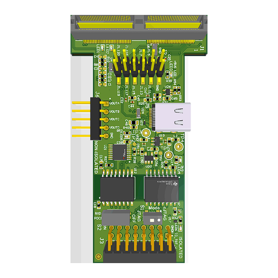
XDS110 Isolated Plug-in Board
Description
The XDS110 isolated plug-in board is a real-time
debug and flash programming design for C2000
and Sitara
™
controlSOMs. The board can connect
to C2000 and Sitara controlSOMs through a non-
isolated 120-pin connector or through an electrically
isolated 16-pin connector. Both connectors feature
JTAG, cJTAG, SWD support, and a full duplex UART
port. The board supports two additional features for
use in target board debug: a serial peripheral interface
(SPI) to four isolated digital-to-analog converter (DAC)
channels, and up to six digital and four analog non-
isolated channels. The embedded emulation logic
allows for emulation and debugging using standard
development tools such as Code Composer Studio
SPRUJE1 – JULY 2024
Submit Document Feedback
Get Started
1. Order the XDS110ISO-EVM from ti.com.
™
2. Download the comprehensive reference design
files.
Features
•
1x USB 2.0 Type-C interface
•
XDS110 onboard emulator
•
16-pin isolated emulator connector
•
5-pin DAC header
•
12-pin debug header
•
120-pin high density connector
•
Adapter boards : 10-pin, 14-pin, and 20-pin
™
.
Copyright © 2024 Texas Instruments Incorporated
Description
XDS110 Isolated Plug-in Board
1
Advertisement
Table of Contents

Subscribe to Our Youtube Channel
Related Manuals for Texas Instruments XDS110ISO-EVM


Summary of Contents for Texas Instruments XDS110ISO-EVM
- Page 1 EVM User's Guide: XDS110ISO-EVM XDS110 Isolated Plug-in Board Description Get Started The XDS110 isolated plug-in board is a real-time 1. Order the XDS110ISO-EVM from ti.com. debug and flash programming design for C2000 ™ 2. Download the comprehensive reference design and Sitara ™...
-
Page 2: Kit Contents
The XDS110 board supports isolated and non-isolated debugging of C2000 and Sitara controlSOMs. The embedded emulation logic allows for emulation and debugging using standard development tools such as Code Composer Studio from TI. 1.2 Kit Contents The XDS110ISO-EVM Kit contains these items: • XDS110 plug-in board •... -
Page 3: Device Information
(HMI) to networked system management controllers. More information about the device can be found in MSP432E401Y SimpleLink™ Ethernet Microcontroller data sheet. SPRUJE1 – JULY 2024 XDS110 Isolated Plug-in Board Submit Document Feedback Copyright © 2024 Texas Instruments Incorporated... - Page 4 TLV70333DBVR – To generate VCC_3V3 rail for XDS110 MCU MSP432 and digital isolators. Additionally, IO_TGT_V_FL is generated by the SOM board for providing 3V3 to digital isolators. XDS110 Isolated Plug-in Board SPRUJE1 – JULY 2024 Submit Document Feedback Copyright © 2024 Texas Instruments Incorporated...
- Page 5 12-pin debug header • 120-pin high density connector 2.1.5 Adapter Boards Adapter boards are added to the XDS110ISO-EVM kit to support the JTAG connections for 10-pin, 14-pin, and 20-pin connectors. The boards pinout is shown in Table 2-1 below. Table 2-1. Adapter Boards Pinout...
-
Page 6: Functional Block Diagram
+5V0_A 2.5 Peripheral and Major Component Description The following sections provide an overview of the different interfaces and circuits on the XDS110 Board. XDS110 Isolated Plug-in Board SPRUJE1 – JULY 2024 Submit Document Feedback Copyright © 2024 Texas Instruments Incorporated... - Page 7 For implementation of cJTAG mode, the TMS signal is also routed through a slower, bidirectional input on a second ISO1644. A switch (S1) is used to select between JTAG and cJTAG mode. SPRUJE1 – JULY 2024 XDS110 Isolated Plug-in Board Submit Document Feedback Copyright © 2024 Texas Instruments Incorporated...
- Page 8 INL: ±8 LSB maximum at 12-bit resolution • Dual reference voltages with range of 0.5V to VA • Power supply: 2.7V to 5.5V • 40MHz, SPI-compatible serial interface XDS110 Isolated Plug-in Board SPRUJE1 – JULY 2024 Submit Document Feedback Copyright © 2024 Texas Instruments Incorporated...
- Page 9 480Mbps data rate. The required power is negotiated between the source device and XDS110 using the TUSB320LAIRWBR CC controller. Figure 2-6. USB Interface block diagram SPRUJE1 – JULY 2024 XDS110 Isolated Plug-in Board Submit Document Feedback Copyright © 2024 Texas Instruments Incorporated...
- Page 10 The bi-directional digital isolator is used to provide digital isolation to the I2C interface. The I2C interface is also directly connected with the controlSOM through the high-density connector. Figure 2-7. I2C Interface Block Diagram XDS110 Isolated Plug-in Board SPRUJE1 – JULY 2024 Submit Document Feedback Copyright © 2024 Texas Instruments Incorporated...
- Page 11 USB port has been attached, the orientation of the cable, and the role detected. The CC logic detects the Type-C current mode as default, medium, or high depending on the role detected. Figure 2-8. Power Input Block Diagram SPRUJE1 – JULY 2024 XDS110 Isolated Plug-in Board Submit Document Feedback Copyright © 2024 Texas Instruments Incorporated...
- Page 12 Figure 2-9. TMS Switch Table 2-4. TMS Switch Selection S1.1 S1.3 TMS Signal Selected 2-wire cJTAG TMS signal 4-wire JTAG TMS signal XDS110 Isolated Plug-in Board SPRUJE1 – JULY 2024 Submit Document Feedback Copyright © 2024 Texas Instruments Incorporated...
- Page 13 UART and SPI Signal Selected S2.1-S2.4 SPI – POCI signal S2.2-S2.3 UART – RX signal Figure 2-10. UART Switch Figure 2-11. SPI Switch SPRUJE1 – JULY 2024 XDS110 Isolated Plug-in Board Submit Document Feedback Copyright © 2024 Texas Instruments Incorporated...
- Page 14 The 5-pin DAC header gives the output from the DAC IC DAC128S085CIMT. See the DAC output header signal details in the table below. Table 2-7. 5-Pin DAC Header (J6) Pinout Sl. No Pin Description OUT_0 OUT_1 OUT_2 OUT_3 XDS110 Isolated Plug-in Board SPRUJE1 – JULY 2024 Submit Document Feedback Copyright © 2024 Texas Instruments Incorporated...
- Page 15 2.5.9.1 Case 1: Non-Isolated XDS110 and controlSOM XDS110 non-isolated plugs into bottom of controlSOM using High density connector (J1). Figure 2-12. Non-Isolated XDS110 and SOM SPRUJE1 – JULY 2024 XDS110 Isolated Plug-in Board Submit Document Feedback Copyright © 2024 Texas Instruments Incorporated...
- Page 16 HSEC adapter plugs into the docking station and XDS110 isolated connector (J3 and J4) plugs vertically into emulation header (J7) and DAC header (J10) of HSEC adapter board. Figure 2-13. Isolated XDS110 + SOM + Baseboard XDS110 Isolated Plug-in Board SPRUJE1 – JULY 2024 Submit Document Feedback Copyright © 2024 Texas Instruments Incorporated...
-
Page 17: Compliance Information
The bill of materials for the LAUNCHXL-F28P55X is included in the XDS110ISO-EVM design files download. 4 Compliance Information 4.1 Compliance and Certifications The EVM is REACH and RoHS compliant. The EU Declaration of Conformity (DoC) for XDS110ISO-EVM can be found here. 5 Additional Information 5.1 Trademarks ™... - Page 18 TI products. TI’s provision of these resources does not expand or otherwise alter TI’s applicable warranties or warranty disclaimers for TI products. TI objects to and rejects any additional or different terms you may have proposed. IMPORTANT NOTICE Mailing Address: Texas Instruments, Post Office Box 655303, Dallas, Texas 75265 Copyright © 2024, Texas Instruments Incorporated...
Need help?
Do you have a question about the XDS110ISO-EVM and is the answer not in the manual?
Questions and answers