Table of Contents
Advertisement
Available languages
Available languages
Quick Links
Advertisement
Chapters
Table of Contents

Related Manuals for ProLights AIR6PIX


Summary of Contents for ProLights AIR6PIX
- Page 1 AIR6PIX MOVING BATTEN USER MANUAL MANUALE UTENTE EN - IT...
- Page 2 AIR6PIX All rights reserved by Music & Lights S.r.l. No part of this instruction manual may be reproduced in any form or by any means for any commercial use. In order to improve the quality of products, Music&Lights S.r.l. reserves the right to modify the characteristics stated in this instruction manual at any time and without prior notice.
-
Page 3: Table Of Contents
3. 23 Special functions 4 Maintenance 4. 1 Maintenance and cleaning the unit 4. 2 Fuse replacement 4. 3 Trouble shooting • AIR6PIX Packing content • Mount bracket • Power supply cable and signal cable • Safety rope • User manual... -
Page 4: General Instructions
AIR6PIX WARNING! Before carrying out any operations with the unit, carefully read this instruction manual and keep it with cure for future reference. It contains important information about the installation, usage and maintenance of the unit. SAFETY General instruction • The products referred to in this manual conform to the European Community Directives and are there- fore marked with . -
Page 5: Introduction
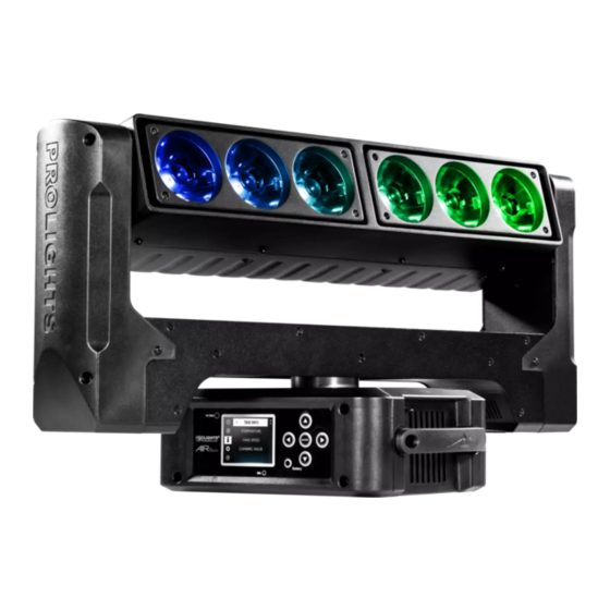
- 1 - INTRODUCTION 1.1 DESCRIPTION AIR6PIX is a moving batten designed to deliver a powerful blade of beams. Each of the 4.5° RGBW LED pixels are individually controllable and both sides pivot to create classic ACL ‘fan’ and ‘knot’ looks. With infinite rotation of both pan and tilt, the only limit is the designer’s imagination... - Page 6 AIR6PIX ELECTRONICS • Dimmer: linear 0~100% electronic dimmer • Dimmer curves: different dimming curves available • Strobe / shutter: 1-25 Hz, electronic • Battery backup: battery backup for user operation without connecting to the main power • Operating temperature: -10° ~ +45°...
-
Page 7: Operating Elements And Connections
AIR6PIX 1.3 OPERATING ELEMENTS AND CONNECTIONS 9 10 11 12 View A View B Fig.2 1. MOVING HEAD 10. EtherCON connector Signal IN/OUT 2. ROTARY ARM 11. DMX IN (5-pole XLR): 3. HANDLE 1 = ground, 2 = DMX-, 3 = DMX+, 4 N/C, 5 N/C 4. -
Page 8: Installation
2.1 MOUNTING The AIR6PIX may be set up on a solid and even surface. By means of the fixing facilities of the baseplate, the unit can also be mounted upside down to a cross arm. The base plate is shown in fig.3. For fixing, stable mounting clips are required. -
Page 9: Functions And Settings
Connect the supplied main cable to a socket (100-240V~/50-60Hz). The unit will run built-in program to reset all motors to their home position. Shortly after that the AIR6PIX is ready for operation. To switch off, disconnect the mains plug from the socket. For a more convenient operation it is recommended to con- nect the unit to a socket which can be switched on and off via light switch. -
Page 10: Menu Structure
AIR6PIX 3.3 MENU STRUCTURE MENU ð ð Connect DMX Address Value (1-512) ð Wireless DMX Value (1-512) ð Art-Net Value (1-488) ð ð Light Max Temperature Value (60°-139° C) ð ð Lamp Adjust Control Value (000-255) ð Value (000-255) ð... - Page 11 AIR6PIX ð 2 Green Value (000-255) ð 2 Blue Value (000-255) ð 2 White Value (000-255) ð 3 Red Value (000-255) ð 3 Green Value (000-255) ð 3 Blue Value (000-255) ð 3 White Value (000-255) ð 6 Red Value (000-255) ð...
- Page 12 AIR6PIX ð Brand Show ON/OFF ð Key Lock ON/OFF ð Language EN/FR/SP... ð ð Users User Mode Standard/Extended/Basic/User ð Edit User Max Channel/Control/Pan/Pan Fine/Tilt/Tilt Fine... ð ð Calibration Password 050 (insert to unlock the following settings) ð Value (-128-127) ð...
-
Page 13: Slave Receive Mode
Select the desired program on the master unit (described in section 3.5). Use the DMX connectors of the AIR6PIX and an XLR cable to form a chain of units. Under certain conditions and lengths you want to make a termination as shown on page 16. -
Page 14: Scenes Record Mode
• Press the LEFT button repeatedly to exit the menu and save changes. 3.6 SCENES RECORD MODE AIR6PIX is equipped with a built-in DMX recorder by which you can transmit the programmed scenes from your DMX-controller to the device. Proceed as follows to store the sequence of scenes in the unit. -
Page 15: Music Mode
AIR6PIX 3.7 MUSIC MODE In music mode, via its integrated microphone, the unit can be controlled by music with a clear rhythm in the bass range. If the music control should not work optimally, increase the volume or reduce the distance between the sound source and the light effect unit or alternatively increase the sensitivity of the micro- phone. -
Page 16: Dmx Configuration
For operation via light control unit with DMX512 protocol, is sufficient connect the controller to AIR6PIX. To able to operate the AIR6PIX with a light controller, adjust the DMX start address for the first a DMX chan- nel. If e. g. address 33 on the controller is provided for controlling the function of the first DMX channel, adjust the start address 33 on the AIR6PIX. -
Page 17: Connection Of The Dmx Line
AIR6PIX 3.13 CONNECTION OF THE DMX LINE DMX connection employs standard XLR connectors. Use shielded pair-twisted cables with 120Ω imped- ance and low capacity. The following diagram shows the connection mode: DMX - INPUT DMX - OUTPUT XLR plug XLR socket... -
Page 18: Dmx Control
AIR6PIX 3.15 DMX CONTROL STAND FUNCTION Value 25 Ch 49 Ch 23 Ch 0~100% 000 - 255 PAN FINE 0~100% 000 - 255 TILT 0~100% 000 - 255 TILT FINE 0~100% 000 - 255 MOVEMENT SPEED Fast to slow 000 - 255... - Page 19 AIR6PIX STAND FUNCTION Value 25 Ch 49 Ch 23 Ch Random Strobe Close 000 - 031 Strobe Rate (slow to fast) 032 - 223 Open 224 - 255 Effect Close 000 - 031 Effect Speed (slow to fast) 032 - 223...
- Page 20 AIR6PIX STAND FUNCTION Value 25 Ch 49 Ch 23 Ch Red=255, Green=0 Blue=0, White->down 226 - 255 VIRTUAL COLOR 2 Color Bounce Black 000 - 003 004 - 005 Green 006 - 007 Blue 008 - 009 White 010 - 011...
- Page 21 AIR6PIX STAND FUNCTION Value 25 Ch 49 Ch 23 Ch BACKGROUND 1 Black 000 - 003 004 - 005 Green 006 - 007 Blue 008 - 009 White 010 - 011 All Color 012 - 015 Red=full, Green->up, Blue=0, White=0 016 - 045 Red->down, Green=full, Blue=0, White=0...
- Page 22 AIR6PIX STAND FUNCTION Value 25 Ch 49 Ch 23 Ch PATTERNS Static Pattern 000 - 031 Dinamic Pattern 1 032 - 047 Dinamic Pattern 2 048 - 063 Dinamic Pattern 3 064 - 079 Dinamic Pattern 4 080 - 095...
- Page 23 AIR6PIX STAND FUNCTION Value 25 Ch 49 Ch 23 Ch GREEN 3 Green 0->100% 000 - 255 BLUE 3 Blue 0->100% 000 - 255 WHITE 3 White 0->100% 000 - 255 RED 4 Red 0->100% 000 - 255 GREEN 4 Green 0->100%...
-
Page 24: Wireless Control Settings
AIR6PIX Fig.8 - LEDs numbering 3.16 WIRELESS CONTROL SETTINGS To enable wireless control mode, proceed as follows: • Press the ENTER button to access the main menu. • Press the UP/DOWN button to scroll the menu, select the Connect icon, then press the ENTER button to enter the next menu. -
Page 25: Fixture Settings
AIR6PIX • Press the UP/DOWN button to scroll through the menu, select Art-Net and press ENTER. • Press the UP/DOWN and LEFT/RIGHT buttons to select the desired value (001-491). • Press the ENTER key to confirm the setting. To change the settings of ethernet, proceed as follows: •... -
Page 26: Display Settings
- Bright Display - Backlight Brightness. Use the arrow buttons to select a value from 0-31. - Brand Show - Displaying the brand. This function allows you to show the brand “PROLIGHTS” on the display. Select ON to activate or OFF to disable. -
Page 27: Reset Functions
• Press the ENTER button to confirm your choice and wait for the recovery of the selected function. 3.23 SPECIAL FUNCTIONS For the AIR6PIX you can access the following special functions: No Signal Select this feature to set the preferred mode of operation to be activated in case the drive is not present no DMX signal input: •... - Page 28 AIR6PIX • Press the LEFT button repeatedly to exit the menu and save changes. Hibernation Select this function to activate the standby mode. This function will be activated automatically after a period of inactivity, which is defined by the user. In standby mode, the lamp and all engines will not be fed if no signal is sent.
- Page 29 AIR6PIX • Once you have entered your password, you can set the values for Pan, Tilt. Press the UP/DOWN button to scroll through the menu, select one of the functions mentioned above and press ENTER to confirm your choice. • Use the arrow buttons to enter the desired value, then press the ENTER button to confirm your choice.
-
Page 30: Maintenance
AIR6PIX - 4 - MAINTENANCE 4.1 MAINTENANCE AND CLEANING THE UNIT • Make sure the area below the installation place is free from unwanted persons during setup. • Switch off the unit, unplug the main cable and wait until the unit has cooled down. -
Page 31: Troubleshooting
AIR6PIX 4.3 TROUBLESHOOTING Problems Possible causes Checks and remedies No mains supply Check the power supply voltage • • Dimmer fader set to 0 Increase the value of the dimmer channels • • All color faders set to 0 Increase the value of the color channels •... - Page 32 Music & Lights S.r.l. si riserva ogni diritto di elaborazione in qualsiasi forma delle presenti istruzioni per l’uso. La riproduzione - anche parziale - per propri scopi commerciali è vietata. Al fine di migliorare la qualità dei prodotti, la Music&Lights S.r.l. si riserva la facoltà di modificare, in qualunque momento e senza preavviso, le specifiche menzionate nel presente manuale di istruzioni.
- Page 33 3. 23 Funzioni speciali 4 Manutenzione 4. 1 Manutenzione e pulizia del sistema ottico 4. 2 Sostituzione fusibile 4. 3 Risoluzione dei problemi • AIR6PIX Contenuto dell'imballo: • Staffa di fissaggio • Cavo di segnale e alimentazione • Cavo di sicurezza...
-
Page 34: Sicurezza
AIR6PIX ATTENZIONE! Prima di effettuare qualsiasi operazione con l’unità, leggere con attenzione questo manuale e conservarlo accuratamente per riferimenti futuri. Contiene informazioni importanti riguardo l’installazione, l’uso e la manutenzione dell’unità. SICUREZZA Avvertenze generali • I prodotti a cui questo manuale si riferisce sono conformi alle Direttive della Comunità Europea e per- tanto recano la sigla . -
Page 35: Introduzione
LED, emissioni di fasci stretti, possibilità di installazione in qualsiasi posizione, movimenti senza limiti sull’asse X e Y, pivot. Inoltre, AIR6PIX è dotato di opzioni multiple di controllo tra cui il DMX-RDM, Art-Net e la con- nessione Wireless DMX. - Page 36 AIR6PIX • RDM per monitor di informazioni sul consumo di corrente, operazioni lampada, tensione di ingresso • Firmware aggiornabile mediante interfaccia USB-DMX • Funzione “Hibernation” quando si presenta una perdita del segnale DMX • Diagnostica avanzata per ogni scheda periferica, con controllo di temperatura e rotazione ventole •...
-
Page 37: Elementi Di Comando E Di Collegamento
AIR6PIX 1.3 ELEMENTI DI COMANDO E DI COLLEGAMENTO 9 10 11 12 Pannello A Pannello B Fig.2 1. TESTA MOBILE 10. CONNETTORI EtherCON segnale IN/OUT 2. BRACCIO GIREVOLE 11. DMX IN (XLR a 5 poli): 3. MANIGLIA PER TRASPORTO 1 = massa, 2 = DMX -, 3 = DMX +, 4 N/C, 5 N/C 4. -
Page 38: Installazione
2.1 MONTAGGIO L’ AIR6PIX può essere collocato su un piano solido. Inoltre, grazie ai fori di fissaggio, l’unità può essere mon- tata anche a testa in giù, su una traversa (fig.3). Per il fissaggio occorrono dei supporti robusti per il mon- taggio. -
Page 39: Funzioni E Impostazioni
è pronta. Per spegnere l’AIR6PIX, staccare la spina dalla presa di rete. Per maggiore comodità è consigliabile collegare l’unità con una presa comandata da un interruttore. 3.2 IMPOSTAZIONE BASE L’AIR6PIX dispone di un display LCD e di 5 pulsanti per l’accesso alle funzioni del pannello di controllo e la loro gestione (fig.4). Battery... -
Page 40: Struttura Menu
AIR6PIX 3.3 STRUTTURA MENU MENU ð ð Connect DMX Address Value (1-512) ð Wireless DMX Value (1-512) ð Art-Net Value (1-488) ð ð Light Max Temperature Value (60°-139° C) ð ð Lamp Adjust Control Value (000-255) ð Value (000-255) ð... - Page 41 AIR6PIX ð 2 Green Value (000-255) ð 2 Blue Value (000-255) ð 2 White Value (000-255) ð 3 Red Value (000-255) ð 3 Green Value (000-255) ð 3 Blue Value (000-255) ð 3 White Value (000-255) ð 6 Red Value (000-255) ð...
- Page 42 AIR6PIX ð Brand Show ON/OFF ð Key Lock ON/OFF ð Language EN/FR/SP... ð ð Users User Mode Standard/Extended/Basic/User ð Edit User Max Channel/Control/Pan/Pan Fine/Tilt/Tilt Fine... ð ð Calibration Password 050 (insert to unlock the following settings) ð Value (-128-127) ð...
-
Page 43: Modalità Slave Receive
Sull’unità master selezionare il programma desiderato come indicato al paragrafo 3.5. Servirsi dei connettori DMX del AIR6PIX e di un cavo XLR per formare una catena di unità. In certe condi- zioni e lunghezze si consiglia di effettuare una terminazione come mostrato a pagina 18. -
Page 44: Modalità Scenes Records
• Premere il tasto LEFT più volte per uscire dal menu e per salvare le modifiche apportate. 3.6 MODALITÀ SCENES RECORD L'AIR6PIX è dotato di un registratore DMX integrato attraverso il quale è possibile trasmettere, dal vostro Controller DMX al dispositivo, le scene programmate. Procedere come segue per memorizzare la sequenza di scene da mandare in esecuzione. -
Page 45: Sensibilità Microfono
• Premere il tasto LEFT più volte per uscire dal menu e per salvare le modifiche apportate. 3.11 CONFIGURAZIONI CANALI DMX L’AIR6PIX dispone di 3 configurazioni dei canali DMX a cui si può accedere dal pannello di controllo. • Premere il tasto ENTER per accedere al menu principale. -
Page 46: Indirizzamento Dmx
Per il funzionamento tramite un’unità di comando luce con protocollo DMX512, è sufficiente collegare l’ AIR6PIX al controller. Il proiettore dispone di configurazione dei canali DMX a cui si può accedere dal pannello di controllo. Per poter comandare l' AIR6PIX con un’unità di comando luce, occorre impostare l’indirizzo di start DMX per il primo canale DMX. -
Page 47: Collegamenti Della Linea Dmx
AIR6PIX 3.13 COLLEGAMENTI DELLA LINEA DMX La connessione DMX è realizzata con connettori standard XLR. Utilizzare cavi schermati, 2 poli ritorti, con impedenza 120Ω e bassa capacità. Per il collegamento fare riferimento allo schema di connessione riportato di seguito: DMX - INPUT... -
Page 48: Canali Dmx
AIR6PIX 3.15 CANALI DMX STAND FUNCTION Value 25 Ch 49 Ch 23 Ch 0~100% 000 - 255 PAN FINE 0~100% 000 - 255 TILT 0~100% 000 - 255 TILT FINE 0~100% 000 - 255 MOVEMENT SPEED Fast to slow 000 - 255... - Page 49 AIR6PIX STAND FUNCTION Value 25 Ch 49 Ch 23 Ch Random Strobe Close 000 - 031 Strobe Rate (slow to fast) 032 - 223 Open 224 - 255 Effect Close 000 - 031 Effect Speed (slow to fast) 032 - 223...
- Page 50 AIR6PIX STAND FUNCTION Value 25 Ch 49 Ch 23 Ch Red=255, Green=0 Blue=0, White->down 226 - 255 VIRTUAL COLOR 2 Color Bounce Black 000 - 003 004 - 005 Green 006 - 007 Blue 008 - 009 White 010 - 011...
- Page 51 AIR6PIX STAND FUNCTION Value 25 Ch 49 Ch 23 Ch BACKGROUND 1 Black 000 - 003 004 - 005 Green 006 - 007 Blue 008 - 009 White 010 - 011 All Color 012 - 015 Red=full, Green->up, Blue=0, White=0 016 - 045 Red->down, Green=full, Blue=0, White=0...
- Page 52 AIR6PIX STAND FUNCTION Value 25 Ch 49 Ch 23 Ch PATTERNS Static Pattern 000 - 031 Dinamic Pattern 1 032 - 047 Dinamic Pattern 2 048 - 063 Dinamic Pattern 3 064 - 079 Dinamic Pattern 4 080 - 095...
- Page 53 AIR6PIX STAND FUNCTION Value 25 Ch 49 Ch 23 Ch GREEN 3 Green 0->100% 000 - 255 BLUE 3 Blue 0->100% 000 - 255 WHITE 3 White 0->100% 000 - 255 RED 4 Red 0->100% 000 - 255 GREEN 4 Green 0->100%...
-
Page 54: Impostazione Controllo Wireless
AIR6PIX Fig.8 - Numerazione LED 3.16 IMPOSTAZIONE CONTROLLO WIRELESS Per abilitare la modalità di controllo wireless procedere nel seguente modo: • Premere il tasto ENTER per accedere al menu principale. • Premere il tasto UP/DOWN per scorrere nel menu, selezionare l’icona Connect, quindi premere il tasto ENTER per accedere al menu successivo. -
Page 55: Impostazioni Del Proiettore
AIR6PIX • Premere il tasto ENTER per confermare l’impostazione. Per modificare le impostazioni ethernet procedere nel seguente modo: • Premere il tasto ENTER per accedere al menu principale. • Premere il tasto UP/DOWN per scorrere nel menu, selezionare l’icona Set, quindi premere il tasto ENTER per accedere al menu successivo. -
Page 56: Impostazioni Display
- Brand Show - Visualizzazione del brand. Questa funzione permette di scegliere se visualizzare o meno il brand “PROLIGHTS” sul display. Selezionare ON per attivare la funzione oppure OFF per disattivar- - Key lock - Blocco tasti. Con questa funzione è possibile bloccare i tasti del pannello di controllo, per evitare, ad esempio, manomissioni delle impostazioni. -
Page 57: Reset Delle Funzioni
• Premere il tasto ENTER per confermare la scelta ed attendere il ripristino della funzione selezionata. 3.23 FUNZIONI SPECIALI Per AIR6PIX è possibile accedere alle seguenti funzioni speciali: No Signal Selezionare questa funzione per impostare la modalità di funzionamento preferita da attivare nel caso in cui nell’unità... - Page 58 • Premere il tasto LEFT più volte per uscire dal menu e per salvare le modifiche apportate. Fixture ID e RDM L’ AIR6PIX possiede la funzione di RDM (Remote Device Management) che rende possibile il controllo re- moto di dispositivi connessi via DMX. Con questa funzione è possibile richiamare i vari sottomenu dell’uni- tà.
- Page 59 AIR6PIX • Tramite i tasti direzionali inserire la password 050 e premere il tasto ENTER per confermare. • Una volta inserita la password è possibile impostare i valori di Pan, Tilt. Premere il tasto UP/DOWN per scorrere nel menu, quindi selezionare una delle funzioni appena citate e premere il tasto ENTER per confermare la scelta.
-
Page 60: Manutenzione
AIR6PIX - 4 - MANUTENZIONE 4.1 MANUTENZIONE E PULIZIA DEL SISTEMA OTTICO • Durante gli interventi, assicurarsi che l’area sotto il luogo di installazione sia libera da personale non qualificato. • Spegnere l’unità, scollegare il cavo di alimentazione ed aspettare finché l’unità non si sia raffreddata. -
Page 61: Risoluzione Dei Problemi
AIR6PIX 4.3 RISOLUZIONE DEI PROBLEMI Anomalie Possibili cause Controlli e rimedi Mancanza di alimentazione di rete Verificare la presenza della tensione alimentazione • • Dimmer impostato a 0 Incrementare i valori del canale dimmer • • Tutti i colori impostati a 0... - Page 64 MUSIC & LIGHTS S.r.l. - Phone +39 0771 72190 - www.musiclights.it...
Need help?
Do you have a question about the AIR6PIX and is the answer not in the manual?
Questions and answers