Table of Contents
Advertisement
Quick Links
UM2896
User manual
Getting started with the EVSPIN32G4-DUAL
Introduction
The EVSPIN32G4-DUAL is a dual-motor demonstration board based on STSPIN32G4 and STDRIVE101.
The STSPIN32G4 is a system in package integrating in a 9x9 mm VFQFPN package, a triple high-performance half bridge gate
driver with a rich set of programmable features, and a mixed signal STM32G431 microcontroller. The STDRIVE101 is a triple
half-bridge gate driver in a compact 4x4 VFQFPN package featuring 600 mA current capability and embedded protections.
The two power stages based on STL110N10F7 power MOSFETs can simultaneously operate up to 10 A
output current and
RMS
74 V supply voltage, providing dedicated sensing for temperature and bus voltage, drain-source voltage monitoring of power
MOSFETs and overcurrent protection.
The board allows sensor-less operation with single-shunt current sensing, taking advantage of operational amplifiers in the
STSPIN32G4, as well as sensor-based control algorithms thanks to dedicated inputs for each motor, including Hall sensors,
incremental encoders and absolute encoders, via SSI communication interface.
The integrated voltage regulators generate the gate driver and control logic supplies directly from the motor supplies, without
further circuitry required.
The predisposition for CAN bus enables the EVSPIN32G4-DUAL to easily connect with master or slave modules, and build
complex motion control systems.
UM2896 - Rev 1 - September 2023
www.st.com
For further information contact your local STMicroelectronics sales office.
Advertisement
Table of Contents

Related Manuals for ST EVSPIN32G4-DUAL


Summary of Contents for ST EVSPIN32G4-DUAL
- Page 1 The integrated voltage regulators generate the gate driver and control logic supplies directly from the motor supplies, without further circuitry required. The predisposition for CAN bus enables the EVSPIN32G4-DUAL to easily connect with master or slave modules, and build complex motion control systems.
-
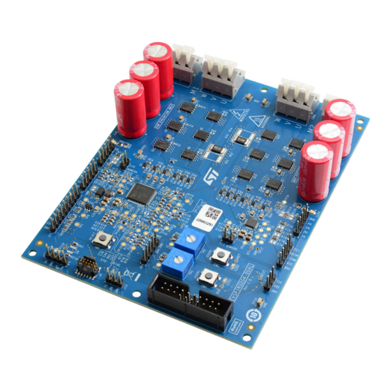
Page 2: Figure 1. Evspin32G4-Dual Demonstration Board
UM2896 Figure 1. EVSPIN32G4-DUAL demonstration board UM2896 - Rev 1 page 2/27... -
Page 3: Safety And Operating Instructions
UM2896 Safety and operating instructions Safety and operating instructions General terms Warning: During assembly, testing, and operation, the evaluation board poses several inherent hazards, including bare wires, moving or rotating parts and hot surfaces. Danger: There is danger of serious personal injury, property damage or death due to electrical shock and burn hazards if the kit or components are improperly used or installed incorrectly. - Page 4 UM2896 Operating the evaluation board Work area safety: – The work area must be clean and tidy. – Do not work alone when boards are energized. – Protect against inadvertent access to the area where the board is energized using suitable barriers and signs.
-
Page 5: Acronyms And Definitions
UM2896 Acronyms and definitions Acronyms and definitions Table 1. List of acronyms and definitions Term Description Analog to Digital Converter. Controller Area Network communication standard used for data transmission among electronic control units connected in a local network. Field Oriented Control driving algorithm for three-phase motors to control the position of the rotor magnetic field with respect to the stator magnetic field. -
Page 6: Hardware And Software Requirements
UM2896 Hardware and software requirements Hardware and software requirements The use of the EVSPIN32G4-DUAL evaluation board requires the following software and hardware: • A Windows ® PC (Windows 10) to install the software package. • One STLINK-V3SET debugger/programmer or equivalent. -
Page 7: Getting Started
Supply the board via CON1 and CON2 connectors respecting polarity; LED3 and LED4 indicate the presence of supply voltage. Upload the firmware onto the STSPIN32G4 microcontroller with a dedicated tool such as STM32CubeProgrammer Run the motor. Table 2. EVSPIN32G4-DUAL specifications Parameter Value Supply voltage Nominal From 10 V to 74 V... -
Page 8: Hardware Description And Configuration
UM2896 Hardware description and configuration Hardware description and configuration Figure 2. Connectors, jumpers, LEDs, switches and test points SWD+UART STPSIN32G4 M2 Speed M1 Speed GPIOs UART STSPIN32G4 CAN bus connector trimmer trimmer connector connector connector connector User switch LED1 user led TP15 Reset switch Ground... - Page 9 UM2896 Connectors and test points Name Label Description CON3 Motor 1 winding 1 Motor 2 winding 3 CON4 Motor 2 winding 2 Motor 2 winding 1 Short circuit protection disabling for motor 1. Default enabled (jumper OPEN) VDSMON Short circuit protection threshold voltage Short circuit protection disabling for motor 2.
-
Page 10: Table 4. Test Points
UM2896 Connectors and test points Name Label Description SPI Ground C signal SCL C signal SDA C ground SPI signal CS for motor 1 absolute encoder MISO SPI signal MISO for motor 1 absolute encoder MOSI SPI signal MOSI for motor 1 absolute encoder SPI signal Clock for motor 1 absolute encoder SPI ground CAN bus signal high... -
Page 11: User Interface
UART on the J10 connector if VCP (Virtual Comm Port) is also required for communication with PC. Hall sensors and encoders The EVSPIN32G4-DUAL evaluation board supports 3 different type of sensors for position feedback: Digital Hall sensors. Quadrature encoder. -
Page 12: Overcurrent Protection
Note: Absolute SSI encoders may require an external RS422/485 transceiver not provided with the board. Overcurrent protection The EVSPIN32G4-DUAL evaluation board implements double protection of each power stage from overcurrent condition thanks to: Drain-source voltage monitoring of each power MOSFETs. -
Page 13: Current Sensing
UM2896 Current sensing • is the threshold voltage applied to the comparator negative input • is the voltage of VREFP pin (3.3 V by default) REF+- • is the value of the shunt resistor (10 mΩ by default) Overcurrent thresholds computed for different threshold voltages are given in the following table. Table 5. -
Page 14: Bus Voltage Sensing
UM2896 Bus voltage sensing Bus voltage sensing The evaluation board provides the sensing of bus voltages that can be used by firmware to implement undervoltage protection. These signals are set through a voltage divider with attenuation 0.04 by the motor supply voltage (resistors R79, R82 and R88, R91), filtered (capacitors C40 and C44) and sent to microcontroller pins PB1 (test point TP22) for motor1 and PC1 (test point TP29) for motor 2. -
Page 15: Input Strategy Selection
UM2896 Input strategy selection Input strategy selection By default, the board is configured to drive STDRIVE101 via ENx/INx mode. All enable signals ENx are shorted together and driven by the microcontroller through pin PB7, while PWM signals are generated via channel 1, 2 and 3 of timer TIM8 on PA15, PB8 and PB9 pins. -
Page 16: Bill Of Material
UM2896 Bill of material Bill of material Table 8. EVSPIN32G4-DUAL bill of materials Item Q.ty Reference Description Value SERIE 4147 - 5.00 MM SCREWLESS CON1, CON2 691414720002B 45° ENTRY 2.00 MM² WIRES WR-TBL SERIE 4147 - 5.00 MM SCREWLESS CON3, CON4 691414720003B 45°... - Page 17 UM2896 Bill of material Item Q.ty Reference Description Value NTC1, NTC2 NTC Thermistor 10 kΩ, 1% Q1, Q2, Q3, Q4, Q5, Q6, Q7, Q8, N-channel 100 V, 5 mΩ typ., 107 A STL110N10F7 Q9, Q10, Q11, Q12 STripFET F7 Power MOSFET R1, R3, R12, R13, R14, R20, R21, R22, R25, R80, R89, R106, R109, SMT resistor 0805...
- Page 18 UM2896 Bill of material Item Q.ty Reference Description Value TP17, TP24, TP32, TP34 Test Point PCB N.M. 3/8 Square Trimpot trimming TR1, TR2 100 kΩ potentiometer, side adjust 3-phase brushless motor controller STSPIN32G4 embedding STM32G4 MCU Three-phase gate driver STDRIVE101 High input voltage 85 mA LDO linear LDK715M50R regulator...
-
Page 19: Schematics
Schematics Figure 4. EVSPIN32G4-DUAL schematic (1 of 4): STSPIN32G4 and STDRIVE101 VDDA VREF+ REG12 VREF+ VREF+ VDDA M1_V M 10uF 100nF 10uF 100nF 100nF 100nF M2_V M VB AT OPEN 220nF 100V OPEN 100nF VDSMON 18uH VDSMON N.M. 100nF VREGIN... -
Page 20: Figure 5. Evspin32G4-Dual Schematic (2 Of 4): Power Stages
Figure 5. EVSPIN32G4-DUAL schematic (2 of 4): Power stages M1_V M M1_V M M1_V M 220nF 220nF 220nF 100V 100V 100V BAT48 BAT48 BAT48 6 7 8 6 7 8 6 7 8 M1_GHS1 M1_GHS2 M1_GHS3 N.M. N.M. N.M. M1_B OOT1... -
Page 21: Figure 6. Evspin32G4-Dual Schematic (3 Of 4): Sensing
Figure 6. EVSPIN32G4-DUAL schematic (3 of 4): Sensing inside STSPIN32G4 CPN2 VREF+ VREF+ OPP1 TP18 OPO1 M1_NTC M1_VBUS M1_V M VDDA TP19 TP20 M1_VM TP22 TP21 NTC1 M1_SPEED VREF+ TP23 72.3k BAT30K M1_S HUN T+ PB 1 100k M1_S HUN T- TP24 3.01k... -
Page 22: Figure 7. Evspin32G4-Dual Schematic (4 Of 4): Inputs And Outputs
Figure 7. EVSPIN32G4-DUAL schematic (4 of 4): Inputs and outputs M2_VM M1_VM CON2 CON1 M2_VM M1_VM M1_VM M2_VM PGND PGND 100uF 100uF 100uF 4.7k 100uF 100uF 100uF 4.7k 100V 100V 100V 0.5W 100V 100V 100V 0.5W TP34 4.7k 4.7k 0.5W 0.5W... -
Page 23: Revision History
UM2896 Revision history Table 9. Document revision history Date Version Changes 21-Sep-2023 Initial release. UM2896 - Rev 1 page 23/27... -
Page 24: Table Of Contents
UM2896 Contents Contents Safety and operating instructions ..........3 General terms . - Page 25 Thermistor temperature with respect to voltage on PC0 or PC2 pins ......14 Figure 4. EVSPIN32G4-DUAL schematic (1 of 4): STSPIN32G4 and STDRIVE101 ......19 Figure 5.
- Page 26 EVSPIN32G4-DUAL specifications........
- Page 27 ST’s terms and conditions of sale in place at the time of order acknowledgment. Purchasers are solely responsible for the choice, selection, and use of ST products and ST assumes no liability for application assistance or the design of purchasers’...
Need help?
Do you have a question about the EVSPIN32G4-DUAL and is the answer not in the manual?
Questions and answers