Table of Contents
Advertisement
Quick Links
bracket.
HD PTZ Camera
3
Quick Start Guide
nt.
46235.025D
45 connector) through the
ith RJ 45 connector.
onnector. Then tighten the
his instruction carefully before using the product
further reference.
Telecamera Speed Dome IP 4Mpx (2560 × 1440), sensore CMOS 1/2,7in, obiettivo
3. Drill the screw holes on the wall
ples and pictures used here are for reference only.
according to the drill template. Then
4,8 ~ 120 mm, filtro IR meccanico, zoom ottico 25x, illuminatori IR con portata
s of this manual are subject to change without
insert the plastic plugs into the holes.
fino a 160m, slot SD CARD 256GB, funzioni di analisi video, WDR, BLC, Defog e
3DNR, RTSP, alimentazione PoE+ (IEEE 802.3at) o 12 Vdc max 22 W, completa
di staffa da parete, grado di protezione IP66. Dimensioni senza staffa ø 173x268
enough to bear the dome
mm. Peso 2100 g.
powered off during
view
Contenuto della confezione
ng mounting. Please select
Una volta ricevuto il dispositivo, controllare gli accessori indicati di seguito. Le illu-
ng instructions are for
1
strazioni sotto riportate hanno solo funzione di riferimento. Far riferimento all'appa-
recchiatura in dotazione.
2
5. Connect the cables and then
hang the bracket on the wall.
Panoramic Bullet
Insert a micro
1 Ethernet connector
SD card
2
Power connector
Network Camera
3 Safety wire
Quick Start Guide
HD PTZ Camera
a micro SD card as indicated
d then install the cover back.
e Connection
Quick Start Guide
is instruction carefully before using the product
Introduzione
rther reference.
Questa telecamera IP Speed Dome è stata progettata per fornire soluzioni TVCC
ad elevate prestazioni. Adotta chip di elaborazione video allo stato dell'arte. Utilizza
les and pictures used here are for reference only.
le tecnologie più avanzate di codifica e decodifica video ed è conforme al protocollo
of this manual are subject to change without
■ Please read this instruction carefully before using the product
TCP/IP, SoC (System on Chip) per assicurare la stabilità e l'affidabilità del sistema.
and keep it for further reference.
I manuali completi e i software CVM, Iptool.exe e Diskcalculator.exe sono disponi-
■ All the examples and pictures used here are for reference only.
bili nella scheda prodotto consultabile nel sito www.vimar.com
■ The contents of this manual are subject to change without
Connessioni
notice.
Di seguito sono riportate le principali connessioni della telecamera.
ng and Caution
1
Overview
oes not work properly, please contact your dealer
ice center. Never attempt to disassemble the
We shall not be responsible for any problems
rized repair or maintenance.)
ater or liquid intrusion into the camera.
3
7
product, you must be strict compliance with the
gulations of the nation and region. When the
d on wall or ceiling, the device shall be firmly
era beyond specified voltage range.
camera or subject it to physical shock.
hole of the product is recommended to be
r enhance the reliability of the camera.
the camera lens.
1 - Interfaccia di rete / Network interface
cessary, please use clean cloth to wipe it gently.
2 - Uscita audio HP / HP audio output
camera at the sun or extra bright place.
3 - Ingresso MIC / MIC IN
2
Cable Connection
4 - Allarmi In/Out / Alarm input/output
camera in extremely hot, cold, dusty or damp
5 - Alimentazione / Power
ot expose it to high electromagnetic radiation.
6 - Massa / Grounding
7 - Filo di sicurezza / Safety wire
ccumulation, good ventilation is required for
ment.
Installazione scheda SD e collegamento dell'alimentazione
ge
Installare la scheda di archiviazione:
1 - Allentare le viti di fissaggio del coperchio posteriore come illustrato di seguito
(Fig. 1).
2 - Inserire la scheda SD nello slot della scheda di archiviazione (Fig. 2).
3 - Rimontare e fissare il coperchio posteriore.
Installazione telecamera
Prima di iniziare, assicurarsi che la parete sia sufficientemente solida
per sopportare il peso della telecamera. Installare la telecamera
in ambiente asciutto. La procedura di montaggio è la seguente:
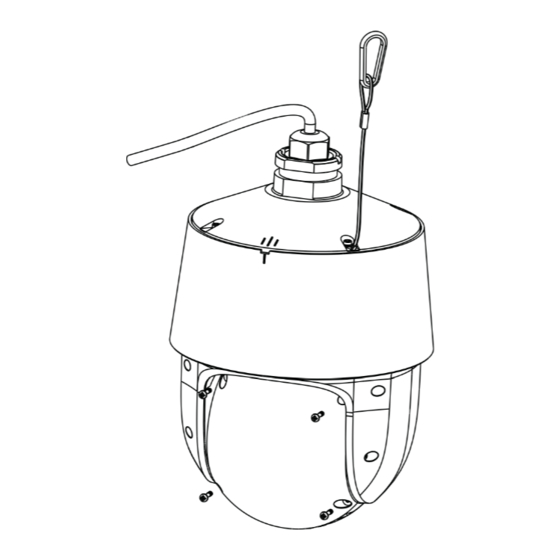
1- Passare i cavi attraverso la staffa. Montare la speed dome sulla staffa (Fig. 3).
2- Fissare la speed dome alla staffa con le viti (Fig. 4)
3- Utilizzare la dima di foratura per praticare i fori per le viti sulla parete (Fig. 5).
4- Allineare le due viti ai fori indicati dalle frecce e lasciare circa 12 mm dal muro
(Fig. 6)
5- Collegare i cavi e quindi appendere la staffa al muro e fissarla (Fig. 7-8).
49401883A0 00 2302
► Connecting Network Cable
4. Insert two screws to the holes
2
1
as indicated by the arrows (left)
and leave 12mm clearance.
① Loosen the nut from the main element.
12
② Run the network cable (without RJ 45 connector) through the
both elements. Then crimp the cable with RJ 45 connector.
③ Connect the cable to the hermetic connector. Then tighten the
■ Please read this instruction carefully before using the product
nut and the main cover.
and keep it for further reference.
■ All the examples and pictures used here are for reference only.
■ The contents of this manual are subject to change without
3
Installation
notice.
6. Attach the bracket to the wall
Telecamera
Istruzioni per l'uso
with four screws.
Camera
Quick start guide
Please make sure the wall is strong enough to bear the dome
camera's weigh and the camera is powered off during
installation.
1
This PTZ camera supports wall or ceiling mounting. Please select
Camera
Quick start guide
a way to install as needed. The following instructions are for
reference only.
► Connecting Network Cable
Micro SD Card Installation
CD
Drill template
Screwdriver
Rubber plug
① Loosen the nut from the main element.
1. Loosen the four screws of
2. Insert a micro SD card as indicated
3
② Run the network cable (without RJ 45 connector) through the
the cover and then remove
Overview
above and then install the cover back.
the cover.
both elements. Then crimp the cable with RJ 45 connector.
2
1
③ Connect the cable to the hermetic connector. Then tighten the
2
3
nut and the main cover.
4
1
5
2
6
1 Ethernet connector
2
Power connector
3 Safety wire
This PTZ camera supports wall or ceiling mounting. Please select
a way to install as needed. The following instructions are for
reference only.
8 9
* 1
It is recommended to install the security cap for outdoor installation.
* 2 This camera can be powered by DC 12V/PoE power supply. If the PoE switch
is used to power the camera, DC12V power supply is not required.
1. Loosen the four screws of
the cover and then remove
the cover.
1. Pull the cables through the
bracket.
Speed Dome IP 4Mpx camera (2560 × 1440), 1/2.7in CMOS sensor, 4.8~120 mm
HD PTZ Camera
3
lens, mechanical IR filter, 25x optical zoom, IR illuminators with a capacity of up to
160m, 256GB SD CARD slots, video analysis functions, WDR, BLC, Defog and
Quick Start Guide
3DNR, RTSP, PoE+ power supply (IEEE 802.3at) or 12 Vdc max 22 W, complete
with wall bracket, IP66 protection degree. Dimensions without bracket ø 173x268
mm. Weight 2100 g.
Package content
After you receive your device, please check the following accessories. The pictures
3. Drill the screw holes on the wall
here are for reference only.
according to the drill template. Then
insert the plastic plugs into the holes.
Dima di foratura
Drill template
Overview
4 tapping screws
3
5. Connect the cables and then
Introduction
hang the bracket on the wall.
×4
Plastic plug
This Speed Dome IP-camera is designed for high performance CCTV solutions. It
adopts state of the art video processing chips. It utilizes most advanced technolo-
gies, such as video encoding and decoding technology, complies with theTCP/IP
Insert a micro
SD card
protocol, SoC (System on chip), etc to ensure this system more stable and reliable.
Complete manuals and CVM, Iptool.exe e Diskcalculator.exe software are available
to download in the Product info sheet section of www.vimar.com website.
1
2
Connections
Here below the main connections of the camera
Cable Connection
1
2
3
Power
3
4
Installation
5
6
7
Please make sure the wall is strong enough to bear the dome
camera's weigh and the camera is powered off during
installation.
1
Ethernet Connector *
HD PTZ Camera
2
Audio Input (MIC)
Quick Start Guide
3
Audio Output (HP)
4
Alarm Input/Output
5
RS485
■ Please read this instruction carefully before using the product
and keep it for further reference.
6
Power Connector *
■ All the examples and pictures used here are for reference only.
Micro SD Card Installation
■ The contents of this manual are subject to change without
7
Ground
notice.
8
Reset
9
Micro SD Card Slot
1
Overview
Install SD Card and Power Connection
3
Install Storage Card:
1 - Loosen the fixed screws of the rear as shown below (Fig. 1).
2 - Insert the SD card into the storage card slot (Fig. 2).
1 Ethernet connector
3 - Install back the cover back.
2
Power connector
3 Safety wire
2. Insert a micro SD card as indicated
Camera Installation
above and then install the cover back.
Before start, please make sure that the wall is strong enough to withstand
the weight of the camera. Please install the camera in the dry environment. The
2
mounting steps are as follows:
Cable Connection
1- Pull the cables through the bracket. Mount the speed dome to the bracket (Fig.
3).
2- Secure the speed dome to the bracket with the screws (Fig. 4).
3- Drill the screw holes on the wall according to the drill template (Fig. 5).
4- Drive the two screws to the holes indicated by the arrows and leave 12mm
clearance (Fig. 6).
5- Connect the cables and then hang the bracket on the wall and fix it (Fig. 7-8).
2. Secure the PTZ camera to the
bracket with screws.
► Connecting Network Cable
4. Insert two screws to the holes
1
as indicated by the arrows (left)
and leave 12mm clearance.
Viti e tasselli
① Loosen the nut from the main element.
Screws and Plastic plug
12
② Run the network cable (without RJ 45 connec
both elements. Then crimp the cable with RJ 45
③ Connect the cable to the hermetic connector.
nut and the main cover.
1
Wall Mounting
1. Pull the cables through the
2
3
6. Attach the bracket to the wall
bracket.
with four screws.
Please make sure the wall is strong enough to
Connecting Alarm Input/Output
●
1 Ethernet connector
camera's weigh and the camera is powered o
Alarm Input
installation.
2
Power connector
3 Safety wire
3
ALARM-INA
3
IPC
This PTZ camera supports wall or ceiling mount
ALARM-GND
4
a way to install as needed. The following instruc
Alarm Output
reference only.
Descrizione/
ALARM-COM
1
Micro SD Card Installation
IPC
Description
+
ALARM-OPEN
2
1
ALARM-GND
3. Drill the screw holes on the wall
Connecting Network Cable
2
ALARM-IN1
●
according to the drill template. Then
3
ALARM-OPEN
insert the plastic plugs into the holes.
4
ALARM-COM
2
1
► Connecting Network Cable
1. Loosen the four screws of
① Loosen the nut from the main element.
the cover and then remove
the cover.
② Run the network cable (without RJ 45 connector) through the
both elements. Then crimp the cable with RJ 45 connector.
③ Connect the cable to the E
thernet
1
2
5. Connect the cables and then
nut and the main cover.
hang the bracket on the wall.
① Loosen the nut from the main element.
② Run the network cable (without RJ 45 connector) through the
4
both elements. Then crimp the cable with RJ 45 connector.
Installation
③ Connect the cable to the hermetic connector. Then tighten the
Insert a micro
nut and the main cover.
SD card
Please make sure that the wall or ceiling is strong enough to
1
2
withstand 3 times the weight of the camera.
3
Installation
① Open the cover of the camera and then insert a micro SD card.
Then install back this cover and fix it firmly with the screws (please
Please make sure the wall is strong enough to bear the dome
keep it flat when installing).
camera's weigh and the camera is powered off during
installation.
This PTZ camera supports wall or ceiling mounting. Please select
a way to install as needed. The following instructions are for
reference only.
Micro SD Card Installation
1. Loosen the four screws of
2. Insert a micro SD card as indicated
the cover and then remove
above and then install the cover back.
the cover.
2
1--ALM-COM
2--ALM-OPEN
3--ALM-INA
2. Secure
4--ALM-GND
Installation
bracket w
RS485T+
RS485T-
Sensor
+
Alarm
5-12 Vdc
-
-
+
-
Power Source
4. Insert
as indica
Contatti N.O./
and leav
Contacts N.O.
12
3
Wall Mounting
2. Insert a micro SD
1. Pull the cables throug
above and then insta
bracket.
connector. Then tighten the
6. Attac
3
with fou
3. Drill the screw holes o
according to the drill tem
insert the plastic plugs in
5. Connect the cables an
hang the bracket on the w
Insert a micro
SD card
Viale Vicenza, 14
36063 Marostica VI - Italy
www.vimar.com
Advertisement
Table of Contents

Related Manuals for Vimar ELVOX TVCC 46235.025D


Summary of Contents for Vimar ELVOX TVCC 46235.025D
- Page 1 ■ All the examples and pictures used here are for reference only. bili nella scheda prodotto consultabile nel sito www.vimar.com to download in the Product info sheet section of www.vimar.com website. 3 Safety wire ■ The contents of this manual are subject to change without...
- Page 2 1) Make sure that the camera and the PC are well connected to the LAN. SD card Eseguire il download di IP-Tool dalla sezione prodotto del sito www.vimar.com e SD card 2) download IP-Tool Product info sheet section of www.vimar.com website and then installarlo sul computer.
- Page 3 Other Consumi/Consumptions Max 22 W Dimensioni/Dimensions (mm) Ø173x268 Peso/Weight (g) 2100 multi-stream staffa inclusa / included bracket - Note database max 10000 volti / database max 10000 faces Viale Vicenza, 14 36063 Marostica VI - Italy www.vimar.com 49401883A0 00 2302...
- Page 4 L’Interessato al momento della richiesta di intervento al Centro Assistenza requesting help from the Vimar Support Centre, so that the related support can be provided. Provision of the Vimar, per poter consentire le attività di assistenza, deve fornire la password di accesso al sistema. La password represents consent for processing.
Need help?
Do you have a question about the ELVOX TVCC 46235.025D and is the answer not in the manual?
Questions and answers