Table of Contents
Advertisement
Quick Links
Model No. PFEL14721-INT.0
Serial No.
Write the serial number in the space
above for reference.
Serial Number
Decal
MEMBER CARE
UNITED KINGDOM
Call: 0330 123 1045
From Ireland: 053 92 36102
Website: iconsupport.eu
E-mail: csuk@iconeurope.com
Write:
ICON Health & Fitness, Ltd.
Unit 4, Westgate Court
Silkwood Park
OSSETT
WF5 9TT
UNITED KINGDOM
AUSTRALIA
Call: 1800 993 770
E-mail: australiacc@iconfitness.com
Write:
iFIT Inc.
PO Box 635
WINSTON HILLS NSW 2153
AUSTRALIA
CAUTION
Read all precautions and
instructions in this manual before
using this equipment. Keep this
manual for future reference.
USER'S MANUAL
iconeurope.com
Advertisement
Table of Contents

Subscribe to Our Youtube Channel
Related Manuals for Pro-Form PFEL14721-INT.0


Summary of Contents for Pro-Form PFEL14721-INT.0
- Page 1 Model No. PFEL14721-INT.0 Serial No. USER’S MANUAL Write the serial number in the space above for reference. Serial Number Decal MEMBER CARE UNITED KINGDOM Call: 0330 123 1045 From Ireland: 053 92 36102 Website: iconsupport.eu E-mail: csuk@iconeurope.com Write: ICON Health & Fitness, Ltd.
-
Page 2: Table Of Contents
TABLE OF CONTENTS WARNING DECAL PLACEMENT ............. . . 2 IMPORTANT PRECAUTIONS . -
Page 3: Important Precautions
IMPORTANT PRECAUTIONS WARNING: To reduce the risk of burns, fire, electric shock, or injury to persons, read all important precautions and instructions in this manual and all warnings on your elliptical before using your elliptical. iFIT assumes no responsibility for personal injury or property damage sus- tained by or through the use of this product. - Page 4 17. Hold the handlebars or the upper body arms 19. Keep your back straight while using the when mounting, dismounting, or using the elliptical; do not arch your back. elliptical. 20. Over exercising may result in serious injury 18. The elliptical does not have a freewheel; the or death.
-
Page 5: Before You Begin
BEFORE YOU BEGIN Thank you for selecting the revolutionary PROFORM ® reading this manual, please see the front cover of this TRAINER E14 elliptical. The TRAINER E14 elliptical manual. To help us assist you, note the product model provides an impressive selection of features designed number and serial number before contacting us. -
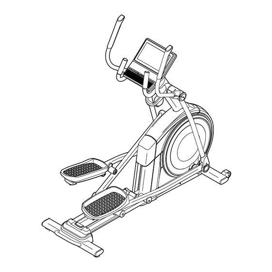
Page 6: Part Identification Chart
PART IDENTIFICATION CHART Use the drawings below to identify the small parts needed for assembly. The number in parentheses below each drawing is the key number of the part, from the PART LIST near the end of this manual. The number following the key number is the quantity needed for assembly. -
Page 7: Assembly
ASSEMBLY • Assembly requires two persons. • In addition to the included tool(s), assembly requires the following tools: • Place all parts in a cleared area and remove the one Phillips screwdriver packing materials. Do not dispose of the packing materials until you fi... - Page 8 2. With the help of a second person, place some of the packing materials (not shown) under the rear of the Frame (1). Have the second person hold the Frame to prevent it from tipping while you complete this step. If there are shipping supports attached to the rear of the Frame (1), remove the screws from the shipping supports, and discard the screws...
- Page 9 4. Identify the Right Roller Arm (59), orient it as shown, and slide it onto the right Crank Arm (20). Attach the Right Roller Arm (59) with an M8 x 20mm Screw (95) and a Crank Cover (77); make sure that the Crank Cover is oriented as shown in the inset drawing.
- Page 10 6. Locate the wire tie (A) in the lower end of the Upright (4). Tie the wire tie to the Main Wire (110) as shown. Then, pull the upper end of the wire tie until the Main Wire is routed through the Upright.
- Page 11 8. Orient the Right Pedal Arm (58) as shown, and then apply grease to the axle. Insert the Right Pedal Arm (58) into the Right Upper Body Leg (60) and into the Right Roller Arm (59). Attach the Right Pedal Arm (58) to the Right Roller Arm (59) with an M8 x 20mm Flat Head Screw (120) and a Retainer (55);...
- Page 12 10. See step 6. Tighten the four M10 x 25mm Screws (92). Next, untie and discard the wire tie on the Main Avoid pinching the Wire (110). Main Wire (110) While a second person holds the Console (7) near the Upright (4), connect the wire (C) on the Console to the Main Wire (110) in the Upright.
- Page 13 12. Orient the Accessory Tray (37) as shown, and attach it to the Upright (4) with two M4 x 16mm Screws (101). 13. Orient a Lower Tray Cover (81) as shown, and attach it to the right side of the Accessory Tray (37) with two M4 x 16mm Screws (101).
- Page 14 15. Orient the Front Shield Cover (117) and the Center Shield Cover (75) around the Upright (4). Then, attach them to each other with two M4 x 16mm Screws (101). Avoid pinching the wires Tip: Avoid pinching the wires. Press the Front Shield Cover (117) and the Center Shield Cover (75) into the Left and Right Shields (73, 74).
- Page 15 17. Orient the Right Arm Front and Rear Covers (65, 66) around the Right Upper Body Leg (60) as shown, and then attach them with two M4 x 16mm Screws (101). Repeat this step on the other side of the elliptical.
-
Page 16: How To Plug In The Power Cord
HOW TO PLUG IN THE POWER CORD This product must be earthed. If it should Follow the steps below to plug in the power cord. malfunction or break down, earthing provides a path of least resistance for electric current to reduce the risk 1. -
Page 17: How To Use The Elliptical
HOW TO USE THE ELLIPTICAL HOW TO MOVE THE ELLIPTICAL HOW TO LEVEL THE ELLIPTICAL Due to the size and weight of the elliptical, moving If the elliptical it requires two persons. Take any necessary rocks slightly measures to protect your floor. Stand in front of on your floor the elliptical, hold the upright (A), and place one foot during use,... - Page 18 HOW TO EXERCISE ON THE ELLIPTICAL THE OPTIONAL TABLET HOLDER To mount the elliptical, hold the handlebars (G) or the The optional tablet upper body arms (H) and step onto the pedal (I) that is holder (J) will hold in the lower position. Then, step onto the other pedal. your tablet securely Push the pedals until they begin to move with a con- in place and enable...
-
Page 19: How To Use The Console
HOW TO USE THE CONSOLE CONSOLE DIAGRAM FEATURES OF THE CONSOLE When you use the manual mode of the console, you can change the resistance of the pedals and the incline The advanced console offers an array of features of the ramp with the touch of a button. designed to make your workouts more effective and enjoyable. - Page 20 HOW TO TURN ON THE CONSOLE HOW TO USE THE TOUCH SCREEN IMPORTANT: If the elliptical has been exposed to The console features a tablet with a full-color touch cold temperatures, allow it to warm to room tem- screen. The following information will help you use the perature before you turn on the console.
- Page 21 HOW TO SET UP THE CONSOLE Firmware updates are always designed to improve your exercise experience. As a result, Before you use the elliptical for the first time, set up the new settings and features may not be described console. in this manual.
- Page 22 HOW TO USE THE MANUAL MODE Drag upward on the screen to enter the fullscreen display mode. Drag downward on the screen to 1. Touch the screen or press any button on the view the workout information displays. console to turn on the console. Touch the various workout information displays See HOW TO TURN ON THE CONSOLE on to view more options.
- Page 23 6. Turn on the fan if desired. THE OPTIONAL HEART RATE MONITOR The fan has several Whether your speed settings, including goal is to an auto mode. While the burn fat or to auto mode is selected, strengthen your the speed of the fan will cardiovascular automatically increase system, the key...
- Page 24 HOW TO USE A FEATURED WORKOUT When you select a workout, the screen will show an overview of the workout that includes details To use a featured workout, the console must be con- such as the duration and distance of the workout nected to a wireless network (see HOW TO CONNECT and the approximate number of calories you will TO A WIRELESS NETWORK on page 30).
- Page 25 IMPORTANT: The calorie goal shown in the 5. Wear headphones if desired. workout description is an estimate of the number of calories that you will burn during To connect your headphones to the console, first the workout. The actual number of calories turn on your headphones, place them in pairing that you burn will depend on various factors, mode, and place them near the console.
- Page 26 HOW TO CREATE A DRAW-YOUR-OWN-MAP If you make a mistake, touch Undo in the map WORKOUT options. 1. Touch the screen or press any button on the The screen will display the elevation and distance console to turn on the console. statistics for your workout.
- Page 27 HOW TO USE AN IFIT WORKOUT 4. Select an iFIT workout from the home screen or the workout library. To use an iFIT workout, you must be logged into your iFIT account (see step 3 below) and the console Touch the buttons at the bottom of the screen to must be connected to a wireless network (see HOW select either the home screen (Home button) or the TO CONNECT TO A WIRELESS NETWORK on...
- Page 28 6. Create a list of favorite iFIT workouts if desired. When your headphones and the console pair successfully, the audio from the console will play To mark an iFIT workout as a favorite, simply view through your headphones. the overview or workout summary of the desired iFIT workout and touch the favorites button (heart 9.
- Page 29 HOW TO CHANGE CONSOLE SETTINGS 3. Customize workout settings. IMPORTANT: Firmware updates are always To customize workout settings and enable workout designed to improve your exercise experience. As a features, touch In Workout, and then touch the result, new settings and features may not be described desired settings.
- Page 30 7. Calibrate the incline system. 3. Enable Wi-Fi. To calibrate the incline system, touch Maintenance, Make sure that Wi-Fi ® is enabled. If it is not touch Calibrate Incline, and then touch Begin. The enabled, touch the Wi-Fi toggle to enable it. ramp will automatically rise to the maximum incline level, lower to the minimum incline level, and then 4.
-
Page 31: Maintenance And Troubleshooting
MAINTENANCE AND TROUBLESHOOTING MAINTENANCE INCLINE SYSTEM TROUBLESHOOTING Regular maintenance is important for optimal If the ramp does not adjust to the selected incline level, performance and to reduce wear. Inspect and see HOW TO CHANGE CONSOLE SETTINGS on properly tighten all parts each time the elliptical is page 29 and calibrate the incline system. - Page 32 HOW TO ADJUST THE REED SWITCH If the console does not display correct feedback, the reed switch should be adjusted. To adjust the reed switch, first press the power switch and unplug the power cord. Next, using a standard screwdriver, carefully pry off the left Disc (71).
-
Page 33: Exercise Guidelines
EXERCISE GUIDELINES Aerobic Exercise—If your goal is to strengthen your WARNING: cardiovascular system, you must perform aerobic Before beginning this exercise, which is activity that requires large amounts or any exercise program, consult your physi- of oxygen for prolonged periods of time. For aerobic cian. - Page 34 SUGGESTED STRETCHES The correct form for several basic stretches is shown at the right. Move slowly as you stretch; never bounce. 1. Toe Touch Stretch Stand with your knees bent slightly and slowly bend forward from your hips. Allow your back and shoulders to relax as you reach down toward your toes as far as possible.
-
Page 35: Part List
PART LIST Model No. PFEL14721-INT.0 R1121A Key No. Qty. Description Key No. Qty. Description Frame/Ramp Roller Rear Stabilizer Left Pedal Handle Access Cover Axle Cover Upright Pivot Spacer M4 x 19mm Screw Retainer Front Stabilizer Roller Arm Bushing Console Pedal Arm Bearing... - Page 36 Key No. Qty. Description Key No. Qty. Description M4 x 16mm Screw Outer Arm Bearing M8 Locknut M4 x 16mm Machine Screw M6 x 12mm Screw Pedal Pin M10 x 115mm Screw M4 x 25mm Screw M4 x 25mm Flange Screw Disc Bracket Lower Ramp Cover Long Bumper...
-
Page 37: Exploded Drawing
EXPLODED DRAWING A Model No. PFEL14721-INT.0 R1121A... - Page 38 EXPLODED DRAWING B Model No. PFEL14721-INT.0 R1121A...
- Page 39 EXPLODED DRAWING C Model No. PFEL14721-INT.0 R1121A...
-
Page 40: Ordering Replacement Parts
ORDERING REPLACEMENT PARTS To order replacement parts, please see the front cover of this manual. To help us assist you, be prepared to provide the following information when contacting us: • the model number and serial number of the product (see the front cover of this manual) •...
Need help?
Do you have a question about the PFEL14721-INT.0 and is the answer not in the manual?
Questions and answers