Table of Contents
Advertisement
Advertisement
Table of Contents
Troubleshooting

Related Manuals for Mitsubishi Electric Mr.SLIM SFZ Series


Summary of Contents for Mitsubishi Electric Mr.SLIM SFZ Series
-
Page 2: Table Of Contents
CONTENTS I SAFETY PRECAUTION [1] SAFETY PRECAUTION ......................1 1.Always observe for safety....................... 1 2.Cautions related to new refrigerant..................1 II PART NAMES AND FUNCTIONS [1] PART NAMES AND FUNCTIONS.................... 7 III SPECIFICATION [1] SPECIFICATION ........................15 IV FAN PERFORMANCE AND CORRECTED AIR FLOW [1] FAN PERFORMANCE AND CORRECTED AIR FLOW ............ - Page 3 HWE1909A...
-
Page 4: I Safety Precaution
[ I SAFETY PRECAUTION ] [1] SAFETY PRECAUTION I SAFETY PRECAUTION MEANINGS OF SYMBOLS DISPLAYED ON THE UNIT This symbol is only for R32 refrigerant. The type of the refrigerant used is written on the nameplate on the outdoor unit. WARNING R32 refrigerant is flammable. - Page 5 [ I SAFETY PRECAUTION ] [1] Warning for service (1) Do not alter the unit. (2) For installation and relocation work, follow the instructions in the Installation Manual and use tools and pipe components specifically made for use with refrigerant specified in the outdoor unit installation manual. (3) Ask a dealer or an authorized technician to install, relocate and repair the unit.
- Page 6 [ I SAFETY PRECAUTION ] [4] Cautions for unit using R32 refrigerant Basic work procedures are the same as those for conventional units using refrigerant R410A. However, pay careful attention to the following points. (1) Information on servicing (1-1) Checks on the Area Prior to beginning work on systems containing flammable refrigerants, safety checks are necessary to ensure that the risk of ignition is minimized.
- Page 7 [ I SAFETY PRECAUTION ] (3) Repair to intrinsically Safe Components Do not apply any permanent inductive or capacitance loads to the circuit without ensuring that this will not exceed the permissible voltage and current permitted for the equipment in use. Intrinsically safe components are the only types that can be worked on while live in the presence of a flammable atmos- phere.
- Page 8 [ I SAFETY PRECAUTION ] (9) Decommissioning Before carrying out this procedure, it is essential that the technician is completely familiar with the equipment and all its detail. It is recommended good practice that all refrigerants are recovered safely. Prior to the task being carried out, an oil and refrigerant sample shall be taken in case analysis is required prior to re-use of reclaimed refrigerant.
- Page 9 [ I SAFETY PRECAUTION ] Unit Electronic weighing scale [5] Service tools Use the below service tools as exclusive tools for R32 refrigerant. Refer to the spec name plate on outdoor unit for the type of refrigerant being used. Tool name Specifications Gauge manifold ·...
-
Page 10: Part Names And Functions
[ II PART NAMES AND FUNCTIONS ] [1] PART NAMES AND FUNCTIONS II PART NAMES AND FUNC TIONS Indoor Unit Air outlet Air intake (sucks the air inside the room into the unit) In case of bottom inlet In case of front inlet - 7 - HWE1909A... - Page 11 [ II PART NAMES AND FUNCTIONS ] • Wired remote controller (Option) PAR-41MAA The functions which can be used are restricted according to each model. Display The factory setting is “Full”. To switch to the “Basic” mode, change the setting on the Main display setting. (Refer to operation manual included with remote controller.) <Full mode>...
- Page 12 [ II PART NAMES AND FUNCTIONS ] Controller interface The functions of the function buttons change depending on the screen. Refer to the button function guide that appears at the bottom of the LCD for the functions they serve on a given screen. When the system is centrally controlled, the button function guide ⑤...
- Page 13 [ II PART NAMES AND FUNCTIONS ] Menu structure Main menu Operation Vane•3D i-See•Vent.(Lossnay) High power Comfort Manual vane angle Vertical air direction Horizontal air direction 3D i-See sensor Timer menu Timer On/Off timer Auto-Off timer Weekly timer OU silent mode Night setback Energy saving Restriction...
- Page 14 [ II PART NAMES AND FUNCTIONS ] Maintenance menu Error information Filter information Cleaning Auto descending panel Descending operation Descending adjustment Service menu Test run menu Test run Drain pump test run Maintenance information Collect model names and serial No. (Mr. SLIM only) Model name input Serial No.
- Page 15 [ II PART NAMES AND FUNCTIONS ] Main menu Setting items Setting details Operation Vane•3D i-See•Vent. Vane: Use to set the vertical air direction. Louver: Use to set the horizontal air direction. (Lossnay) 3D i-See sensor: This setting is available only for the air (Vane•Vent.(Lossnay)) conditioners that support easy setting function of motion sensing air direction.
- Page 16 [ II PART NAMES AND FUNCTIONS ] Main menu Setting items Setting details Energy Energy Schedule Set the start/stop times to operate the units in the energy-save saving saving mode for each day of the week, and set the energy-saving rate. •...
- Page 17 [ II PART NAMES AND FUNCTIONS ] Wireless remote controller (option) Operation buttons CHECK TEST RUN SET TEMPERATURE button ON/OFF button MODEL SELECT SET TEMPERATURE button sets and Pushing button starts operation. any desired room temperature. Pushing again stops operation. NOT AVAILABLE TEMP ON/OFF...
-
Page 18: Specification
[ III SPECIFICATION ] [1] SPECIFICATION III SPECIFICATION Service Ref. SFZ-M25VA(-ET).TH Mode Cooling Heating Power supply Input 0.041 0.041 Running Current 0.44 0.44 Plate fin coil Fan (drive) × No. Sirocco fan × 2 Fan motor output /min (CFM) External static pressure Sound pressure level 25Pa dB (A) - Page 19 [ III SPECIFICATION ] Service Ref. SFZ-M60VA(-ET).TH Mode Cooling Heating Power supply Input Running Current Plate fin coil Fan (drive) × No. Sirocco fan × 4 Fan motor output /min (CFM) External static pressure Sound pressure level 25Pa dB (A) 40Pa Field drain pipe O.D mm (in.)
-
Page 20: Fan Performance And Corrected Air Flow
[ IV FAN PERFORMANCE AND CORRECTED AIR FLOW ] [1] FAN PERFORMANCE AND CORRECTED AIR FLOW IV FAN PERFORMANCE AND CORRECTED AIR FLOW SFZ-M25VA(-ET).TH SFZ-M35VA(-ET).TH External static pressure : 25Pa External static pressure : 25Pa Power source : 220-240V Power source : 220-240V Limit Limit High... - Page 21 [ IV FAN PERFORMANCE AND CORRECTED AIR FLOW ] SFZ-M50VA(-ET).TH SFZ-M60VA(-ET).TH External static pressure : 25Pa External static pressure : 25Pa Power source : 220-240V Power source : 220-240V Limit Limit High High Middle Middle Rated point Rated point Airflow rate (m /min) Airflow rate (m /min)
- Page 22 [ IV FAN PERFORMANCE AND CORRECTED AIR FLOW ] SFZ-M71VA(-ET).TH External static pressure : 25Pa Power source : 220-240V Limit High Rated point Middle Airflow rate (m /min) SFZ-M71VA(-ET).TH External static pressure : 40Pa Power source : 220-240V Limit High Rated point Middle Airflow rate (m...
-
Page 23: Sound Pressure Levels
[ V SOUND PRESSURE LEVELS ] [1] SOUND PRESSURE LEVELS V SOUND PRESSURE LEVELS 1. Sound pressure level Floor standing concealed Measurement location 1.5m Aux. duct * Measurements were taken without the duct being connected to the indoor unit outlet when the external static pressure is 0 Pa. 2. - Page 24 [ V SOUND PRESSURE LEVELS ] SFZ-M35VA(-ET).TH (External static pressure 0Pa) (External static pressure 40Pa) 70.0 70.0 High High Middle Middle 65.0 65.0 60.0 60.0 NC-60 NC-60 55.0 55.0 50.0 50.0 NC-50 NC-50 45.0 45.0 40.0 40.0 NC-40 NC-40 35.0 35.0 30.0 30.0...
- Page 25 [ V SOUND PRESSURE LEVELS ] SFZ-M50VA(-ET).TH (External static pressure 0Pa) (External static pressure 40Pa) 70.0 70.0 High High Middle Middle 65.0 65.0 60.0 60.0 NC-60 NC-60 55.0 55.0 50.0 50.0 NC-50 NC-50 45.0 45.0 40.0 40.0 NC-40 NC-40 35.0 35.0 30.0 30.0...
- Page 26 [ V SOUND PRESSURE LEVELS ] SFZ-M60VA(-ET).TH (External static pressure 0Pa) (External static pressure 40Pa) 70.0 70.0 High High Middle Middle 65.0 65.0 60.0 60.0 NC-60 NC-60 55.0 55.0 50.0 50.0 NC-50 NC-50 45.0 45.0 40.0 40.0 NC-40 NC-40 35.0 35.0 30.0 30.0...
- Page 27 [ V SOUND PRESSURE LEVELS ] SFZ-M71VA(-ET).TH (External static pressure 0Pa) (External static pressure 40Pa) 70.0 70.0 High High Middle Middle 65.0 65.0 60.0 60.0 NC-60 NC-60 55.0 55.0 50.0 50.0 NC-50 NC-50 45.0 45.0 40.0 40.0 NC-40 NC-40 35.0 35.0 30.0 30.0...
-
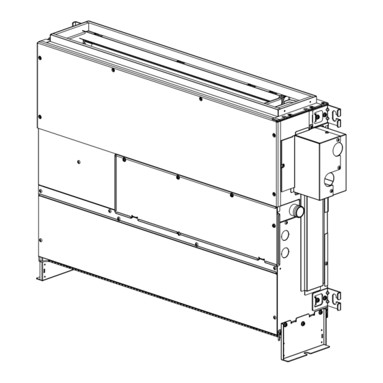
Page 28: Outlines & Dimensions
[ VI OUTLINES & DIMENSIONS ] [1] OUTLINES & DIMENSIONS VI OUTLINES & DIMENSIONS INDOOR UNIT SFZ-M25, 35, 50, 60, 71VA(-ET).TH Bottom suction wall mounting Unit: mm - 25 - HWE1909A... - Page 29 [ VI OUTLINES & DIMENSIONS ] Unit: mm SFZ-M25,35,50,60,71VA(-ET).TH Bottom suction·wall mounting 〔Maintenance access space〕 Secure enough access space to allow for the maintenance, inspection, and replacement of the motor, fan, heat exchanger, drain pan and control box. Top view Unit Maintenance space Front view...
- Page 30 [ VI OUTLINES & DIMENSIONS ] INDOOR UNIT SFZ-M25, 35, 50, 60, 71VA(-ET).TH Bottom suction wall mounting Unit: mm - 27 - HWE1909A...
- Page 31 [ VI OUTLINES & DIMENSIONS ] Unit: mm SFZ-M25,35,50,60,71VA(-ET).TH Bottom suction·wall mounting 〔Maintenance access space〕 Secure enough access space to allow for the maintenance, inspection, and replacement of the motor, fan, heat exchanger, drain pan and control box. Top view Unit Maintenance space Front view...
-
Page 32: Wiring Diagram
[ VII WIRING DIAGRAM ] [1] WIRING DIAGRAM VII WIRING DIAGRAM SFZ-M25, 35, 50, 60, 71VA(-ET).TH - 29 - HWE1909A... -
Page 33: Refrigerant System Diagram
[ VIII REFRIGERANT SYSTEM DIAGRAM ] [1] REFRIGERANT SYSTEM DIAGRAM VIII REFRIGERANT SYSTEM DIAGRAM SFZ-M25, 35, 50, 60, 71VA(-ET).TH Strainer (#50) Heat exchanger Refrigerant GAS pipe connection (Flare) Thermistor TH5 (Cond./ Eva.temperature) Refrigerant flow in cooling Refrigerant flow in heating Refrigerant LIQUID pipe connection (Flare) Thermistor TH2... -
Page 34: Troubleshooting
[ IX TROUBLESHOOTING ] [1] TROUBLESHOOTING IX T ROUBLESHOOTING 1. Cautions on troubleshooting (1) Before troubleshooting, check the followings: 1 1 1 Check the power supply voltage. Check the indoor/outdoor connecting wire for mis-wiring. (2) Take care the followings during servicing. Before servicing the air conditioner, be sure to turn off the remote controller first to stop the main unit, and then turn off the breaker. - Page 35 [ IX TROUBLESHOOTING ] • If the unit cannot be operated properly after the test run has been performed, refer to the following table to remove the cause. Symptom Cause Wired remote controller LED 1, 2 (PCB in outdoor unit) •...
- Page 36 [ IX TROUBLESHOOTING ] [Output pattern A] Errors detected by indoor unit Wired remote Wireless remote controller controller Symptom Remark Beeper sounds/OPERATION INDICATOR lamp flashes Check code (Number of times) Intake sensor error Pipe (Liquid or 2-phase pipe) sensor error P2, P9 Indoor/outdoor unit communication error E6, E7...
- Page 37 [ IX TROUBLESHOOTING ] For description of each LED (LED1, 2, 3) provided on the indoor controller, refer to the following table. LED 1 (power for microcomputer) Indicates whether control power is supplied. Make sure that this LED is always lit. LED 2 (power for remote controller) Indicates whether power is supplied to the remote controller.
-
Page 38: Self-Diagnosis Action Table
[ IX TROUBLESHOOTING ] 3. Self-diagnosis action table Note: Refer to the manual of outdoor unit for the details of display such as F, U, and other E. Abnormal point and detection method Countermeasure Error Code Cause Room temperature Defective thermistor –... - Page 39 [ IX TROUBLESHOOTING ] Abnormal point and detection method Countermeasure Error Code Cause Freezing/overheating protection is (Cooling or drying mode) (Cooling or drying mode) working Clogged filter (reduced airflow) Check clogging of the filter. Freezing protection (Cooling mode) Short cycle of air path Remove shields.
- Page 40 [ IX TROUBLESHOOTING ] Abnormal point and detection method Countermeasure Error Code Cause Abnormality of pipe temperature ther- Defective thermistor – Check resistance value of thermistor. mistor/Condenser-Evaporator (TH5) characteristics For characteristics, refer to (P1) above. The unit is in three-minute resume pro- Contact failure of connector Check contact failure of connector (CN44) tection mode if short/open of thermistor...
- Page 41 [ IX TROUBLESHOOTING ] Abnormal point and detection method Countermeasure Error Code Cause Indoor/outdoor unit communication * Check LED display on the outdoor control cir- Contact failure, short circuit or, error (Signal receiving error) cuit board. (Connect A-control service tool, mis-wiring (converse wiring) of Abnormal if indoor controller board PAC-SK52ST.)
- Page 42 [ IX TROUBLESHOOTING ] Abnormal point and detection method Countermeasure Error Code Cause Water leakage Mis-piping of extension pipes Check the extension pipes for mis-piping. This detection is performed during the (When connected with multiple operation (stop, heating, fan, or error stop units) mode etc.) other than cooling and dry.
-
Page 43: Troubleshooting Of Problems
[ IX TROUBLESHOOTING ] 4. Troubleshooting of problems Note: Refer to the manual of outdoor unit for the detail of remote controller. Cause Phenomena Countermeasure (1) LED2 on indoor controller board is • When LED1 on indoor controller board is also off. off. -
Page 44: Test Point Diagram
[ IX TROUBLESHOOTING ] 5. Test point diagram Indoor controller board CN01 Power supply voltage (220 - 240VAC) Emergency operation CN2L J41, J42 Pair No. setting for wireless remote controller LED3 Capacity setting CN90 CN22 For MA remote controller cable connection (10.4 - 14.6 VDC (Between 1 and 3.)) CN51 Centralized control... -
Page 45: Trouble Criterion Of Main Parts
[ IX TROUBLESHOOTING ] 6. Trouble criterion of main parts Part name Check method and criterion Room temperature Measure the resistance with a tester. thermistor (Part temperature 10°C ~ 30°C) (TH1) Normal Abnormal Pipe temperature 4.3kΩ~9.6kΩ Opened or short-circuited thermistor/liquid (TH2) Condenser/evaporator temperature thermistor... -
Page 46: Dc Fan Motor (Fan Motor/Indoor Controller Board)
[ IX TROUBLESHOOTING ] 8. DC fan motor (fan motor/indoor controller board) Check method of DC fan motor (fan motor/indoor controller circuit board) Notes · High voltage is applied to the connecter (CNMF) for the fan motor. Give attention to the service. ·... -
Page 47: Functions Of Dip Switch And Jumper Wire
[ IX TROUBLESHOOTING ] 9. Functions of dip switch and jumper wire Each function is controlled by the dip switch and the jumper wire on control p.c. board. Model setting and capacity setting are memorized in the nonvolatile memory of the control p.c. board of the unit. -
Page 48: Disassembly Procedure
[ X DISASSEMBLY PROCEDURE ] [1] DISASSEMBLY PROCEDURE X DISASSEMBLY PROCEDURE 1. Control box Exercise caution when removing heavy parts. 1. Removing the control box cover (1) Remove the three fixing screws on the cover Fixing screws (A) to remove it. Fig. -
Page 49: Drain Pan
[ X DISASSEMBLY PROCEDURE ] 3. Drain pan Exercise caution when removing heavy parts. 1. Remove the control box cover (A) with proce- dure [1]-1. 2. Remove the fixing screws on the front plate (D), (E) to remove it. (Fig. 4) Fig. -
Page 50: Thermistor (Condenser/Evaporator) (Liquid Pipe)
[ X DISASSEMBLY PROCEDURE ] 4. Thermistor (Condenser/evaporator) (Liquid pipe) Exercise caution when removing heavy parts. 1. Remove the drain pan according to the proce- dure [1]-3. 2. Removing the Heat exchanger cover (1) Remove a fixing screw on the heat exchanger cover (G) to remove it. -
Page 51: Fan And Fan Motor
[ X DISASSEMBLY PROCEDURE ] 5. Fan and fan motor Exercise caution when removing heavy parts. 1. Removing the filter, control box cover, front plate and control box. (1) Push down the tab on the filter, and pull out the filter in the direction of the arrow 1. -
Page 52: Bearing
[ X DISASSEMBLY PROCEDURE ] 6. Bearing Exercise caution when removing heavy parts. M35, 50, 60, 71 models only. 1. Removing the bearing (1) Remove the two fixing screws on the bearing cover (M) to remove it. (Fig. 14) Fig. 14 (2) Remove the two bearing retainer screws to remove the bearing. -
Page 53: Heat Exchanger
[ X DISASSEMBLY PROCEDURE ] 7. Heat exchanger Exercise caution when removing heavy parts. 1. Removing the cover 1 and cover 2 (1) Remove the eight fixing screws on the cover 1 (N) and cover 2 (P) to remove them. (Fig. 16) Fig. - Page 54 [ X DISASSEMBLY PROCEDURE ] Exercise caution when removing heavy parts. 5. Removing the Heat exchanger (1) Remove the fixing screws on the heat exchanger (R) to remove it (Fig.18, 19). Fig. 18 Fig. 19 Note: • In order to attach and fix the heat exchanger, insert the hook (a) on the heat exchanger (Fig.
-
Page 55: R32 Sensor
[ X DISASSEMBLY PROCEDURE ] 8. R32 sensor Exercise caution when removing heavy parts. 1. Remove the control box cover and front plate (1) Remove the control box cover (A) with procedure [1]-1. (2) Remove the front plate (K) with procedure [1]-5.
Need help?
Do you have a question about the Mr.SLIM SFZ Series and is the answer not in the manual?
Questions and answers