
Subscribe to Our Youtube Channel
Related Manuals for Life Fitness Row HX


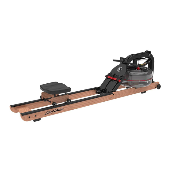
Summary of Contents for Life Fitness Row HX
- Page 1 Row HX Service Manual HXD-ALLLX-101, HXL-ALLLX-101 Service Manual REV June 24, 2022...
- Page 3 Latin America and Caribbean* Spain Hong Kong Life Fitness, LLC Life Fitness IBERIA Life Fitness Asia Pacific LTD 10601 W Belmont Ave C/Frederic Mompou 5,1º1ª 26/F, Global Trade Square Franklin Park, IL 60131 U.S.A. 08960 Sant Just Desvern Barcelona...
-
Page 4: Table Of Contents
© Copyright , Life Fitness, LLC. All Rights Reserved. Life Fitness, Hammer Strength, Cybex, ICG and SCIFIT are registered trademarks of Life Fitness, LLC and its affiliated companies and subsidiaries. Disclaimer: Images and specifications are current as of the date of publication and are subject to change. -
Page 5: Safety Instructions
• This equipment is not intended for use by children. Keep children under the age of 14 away from the machine. • DO NOT use or permit use of any equipment that is damaged and/or has worn or broken parts. For all Life Fitness Family of Brands equipment use only replacement parts supplied by Life Fitness Family of Brands. - Page 6 • Ensure that any person(s) making adjustments or performing maintenance or repair of any kind is qualified to do • DO NOT ATTEMPT TO USE OR REPAIR ANY ACCESSORY APPROVED FOR USE WITH THE LIFE FITNESS EQUIPMENT WHICH APPEARS TO BE DAMAGED OR WORN.
-
Page 7: Introduction
Life Fitness, Hammer Strength, and ICG. • http://www.lifefitness.com/parts service parts ordering for Life Fitness, Cybex, SCIFIT, Hammer Strength, and ICG products along with warranty parts ordering and technician requests. • https://lfworld.lifefitness.com easy to find Knowledge Base articles with answers to frequently asked questions and product support documentation for Life Fitness, Cybex, SCIFIT, Hammer Strength, and ICG. -
Page 8: Maintenance
Vertical Storage (Not Available in All Areas) The Row HX Trainer can be stored in a vertical, upright position with use of the optional vertical storage stand specified for this machine and with water in the tank. For safety, store on level ground in a suitable location, such as a corner of a room. -
Page 9: Areas)
Optional Storage (Not Available in All Areas) 1. Install the Z brackets, bolts, and knobs onto the stand base by hand. Item Description Qty. Stand base Bolt Knob Z bracket 2. Install the stand base onto the frame as shown. Tighten knob by hand to secure stand base to rower. Item Description Qty. -
Page 10: Theory Of Operation
These components support the base of and the user while they are on the Row HX Trainer. The Lower frame holds the front of the Row HX Trainer in place, secures the upper frame to the rest of the unit, and holds the footplate in place. -
Page 11: How To's
5. How To's Knowledge Base Knowledge Base for more detailed information. Adjust Recoil Tension Recoil tension can be adjusted for different users. Tools required: None 1. Disconnect bungee cord from rear leg. Item Description Qty. Hook assembly Bungee cord TIP: Tie a slip knot in the bungee cord next to the lower pulley. This allows for easier adjustment of the recoil tension. - Page 12 3. Adjust recoil tension by sliding the inner clip up or down the bungee cord. Increase tension Decrease tension Item Description Bungee cord Bungee hook end frame Inner clip 4. Insert inner clip into bungee hook end frame. Item Description Bungee cord Bungee hook end frame Inner clip...
-
Page 13: Water Treatment
Water Treatment Parts required: Water treatment tablet, part number 0K106-10131-0000 Over time the water in the tank may become cloudy. This can be caused by poor quality water or direct sunlight. NOTE: Where water quality is known to be poor, we recommend the use of distilled water. 1. -
Page 14: Remove Water From
Remove Water from Tank Tools required: • Siphon, included with rower • Bucket, 5 gallons (19 liters) • Drop cloth CAUTION: Use a drop cloth under the tank when filling to avoid staining floor or carpet. 1. Turn resistance knob clockwise to minimum position. Item Description Qty. - Page 15 4. Place siphon into tank and siphon hose into bucket. Item Description Qty. Siphon Bucket Siphon in tank 5. Use siphon to remove water from tank. Approximately 40% of water will remain. NOTE: The siphon valve must be closed to allow siphoning action to occur. 6.
-
Page 16: Rower Belt
Rower Belt Tools Required: None Time: 15 minutes Remove Rower Belt 1. Disconnect bungee cord from rear leg. Item Description Qty. Hook assembly Bungee cord 2. Push out inner clip from bungee hook end frame. Item Description Bungee cord Bungee hook end frame Inner clip 3. - Page 17 4. Remove bungee cord by pulling through lower and upper pulleys. Item Description Bungee cord Upper pulley Lower pulley Belt and bungee pulley 5. Remove rower belt by slowly pulling beyond the normal range of regular rowing stroke. The velcro on the belt and bungee pulley will make a noise as it separates.
- Page 18 4. Wind the rower belt around the belt pulley until the handle assembly is at the furthest forward position. Item Description Handle assembly Belt pulley 5. Route the bungee cord through the upper and lower pulleys. Item Description Bungee cord Upper pulley Lower pulley Belt and bungee pulley...
- Page 19 8. Hook bungee cord onto hook assembly. Item Description Qty. Hook assembly Bungee cord Adjust Recoil Tension Recoil tension can be adjusted for different users. Tools required: None 1. Disconnect bungee cord from rear leg. Item Description Qty. Hook assembly Bungee cord TIP: Tie a slip knot in the bungee cord next to the lower pulley.
- Page 20 2. Push out inner clip from bungee hook end frame. Item Description Bungee cord Bungee hook end frame Inner clip 3. Adjust recoil tension by sliding the inner clip up or down the bungee cord. Increase tension Decrease tension Item Description Bungee cord Bungee hook end frame...
- Page 21 5. Hook bungee cord onto hook assembly. NOTE: If slip knot was tied into bungee cord, undo before installing bungee cord to hook assembly. Complete Installation Operate unit at all levels to verify proper operation. Page 19 of 47...
-
Page 22: Upper Pulley
Upper Pulley Tools Required: • 5 mm Allen wrench • 13 mm Open end wrench Time: 15 minutes Remove Upper Pulley 1. Remove the dome head nut using a 5 mm Allen wrench and 13 mm open end wrench. Item Description Qty. - Page 23 Install Upper Pulley 1. Place upper pulley in frame. Item Description Qty. Frame Upper pulley 2. Insert bolt into frame while holding upper pulley. Item Description Qty. Dome head nut Bolt, M8 x 65 Frame 3. Install the dome head nut using a 5 mm Allen wrench and 13 mm open end wrench. NOTE: Do not over tighten.
-
Page 24: Water Tank
Water Tank Tools Required: • Siphon, included with rower • 6 mm Allen wrench • Phillips screwdriver • Bucket, 5 gallons (19 liters) • 7 mm Open end wrench • Punch • Drop cloth • 13 mm Open end wrench •... - Page 25 4. Place siphon into tank and siphon hose into bucket. Item Description Qty. Siphon Bucket Siphon in tank 5. Use siphon to remove water from tank. Approximately 40% of water will remain. NOTE: The siphon valve must be closed to allow siphoning action to occur. 6.
- Page 26 Remove Water Tank 1. Disconnect bungee cord from rear leg. Item Description Qty. Hook assembly Bungee cord 2. Push out inner clip from bungee hook end frame. Item Description Bungee cord Bungee hook end frame Inner clip 3. Pull bungee cord through inner clip until free. 4.
- Page 27 5. Remove eight M8 x 45 mm bolts, sixteen M8 washers, eight M8 nuts, and eight M8 Nylock nuts, using a 6 mm Allen wrench and 13 mm open end wrench. Item Description Qty. Main assembly Rail assembly M8 x 45 mm bolt M8 washer M8 nut M8 Nylock nut...
- Page 28 8. Remove two socket head screws and two pan head screws securing bottom rails to main assembly using a 6 mm Allen wrench. Item Description Main assembly Socket head screws Pan head screws Bottom rails 9. Remove twelve bolts and nuts securing tank shells together using a 2.5 mm Allen wrench and a 7 mm open end wrench.
- Page 29 12. Remove impeller from upper tank shell. Item Description Impeller Upper tank shell 13. Remove belt bungee pulley and end cap from frame. Item Description Belt bungee pulley End cap 14. Remove twelve screws securing inner reserve tank using a Phillips screwdriver. Item Description Inner reserve tank...
- Page 30 15. Remove two M6 screws, spacers, and O-rings securing upper tank shell to frame using a Phillips screwdriver. Item Description Upper tank shell M6 screws, spacers, and O-rings 16. Remove upper tank shell. Install Water Tank Alignment tools are recommended to align upper tank. Item Description Lower alignment tool...
- Page 31 3. Insert upper alignment tool through upper tank and into lower alignment tool. Item Description Lower alignment tool Upper tank 4. Install two M6 screws, spacers, and O-rings securing upper tank shell to frame using a Phillips screwdriver. NOTE: Upper tank hole must be aligned with main frame hole. Item Description Upper tank shell...
- Page 32 6. Insert adjuster knob into upper tank shell. NOTE: Align the adjuster knob edge with the inner cup notch. Item Description Inner cup Adjuster knob 7. Install belt bungee pulley and end cap to frame. Item Description Belt bungee pulley End cap 8.
- Page 33 9. Align holes in belt pulley and impeller shaft. Item Description Belt pulley Roll pin 10. Install belt pulley roll pin using a punch and hammer. 11. Install twelve bolts and nuts securing tank shells together using a 2.5 mm Allen wrench and a 7 mm open end wrench.
- Page 34 13. Install two socket head screws and two pan head screws securing bottom rails to main assembly using a 6 mm Allen wrench. Item Description Main assembly Socket head screws Pan head screws Bottom rails Page 32 of 47...
- Page 35 14. Place the main assembly into position on seat rail assembly. Item Description Qty. Main assembly Rail assembly M8 x 45 mm bolt M8 washer M8 nut M8 Nylock nut 15. Install eight M8 x 45 mm bolts, sixteen M8 washers, eight M8 nuts, and eight M8 Nylock nuts, using a 6 mm Allen wrench and 13 mm open end wrench.
- Page 36 16. Install rower belt around belt pulley with velcro side facing upwards. Item Description Rower belt Belt pulley 17. Thread belt around idle wheel. Item Description Rower belt Belt pulley 18. Install rower belt to bungee pulley. There is a lip where the belt installs to the pulley. 19.
- Page 37 20. Route the bungee cord through the upper and lower pulleys. Item Description Bungee cord Upper pulley Lower pulley Belt and bungee pulley 21. Insert bungee cord into bungee hook end frame. Item Description Bungee cord Bungee hook end frame Inner clip 22.
- Page 38 Tank Filling Tools required: • Siphon, included with rower • Bucket, 5 gallons (19 liters) • Water • Drop cloth NOTE: Where water quality is known to be poor, we recommend the use of distilled water. CAUTION: Use a drop cloth under the tank when filling to avoid staining floor or carpet. 1.
- Page 39 3. Place siphon into bucket and siphon hose into tank. Item Description Qty. Siphon Bucket Siphon hose in tank Max fill line 4. Pump 4.5 Gallons (17 Liters) of water into tank. NOTE: The siphon valve must be closed to allow siphoning action to occur. NOTE: Do not fill past max fill line on side of tank.
-
Page 40: Troubleshooting
Contact your local rowing. erratic computer display). service center if this fails to address the problem. The Row HX Trainer computer Batteries installed incorrectly Reinstall batteries in correct position and try again. If the LCD does not illuminate after or need replacing. -
Page 41: No Data On
No Data on Console 1. Check for data on the console. If no data is shown on the console when rowing , there might be an issue with the reed sensor. If the Reed sensor is functioning, all data (Time, Watts, Distance, Cal and Chart) will change. 2. -
Page 42: No Change When Adjusting Resistance
No Change when Adjusting Resistance Knob View the Levels section on the console. If there are no changes on the console when changing levels with resistance knob, there might be an issue with the potentiometer. Page 40 of 47... -
Page 43: Cracked Water Tank
Cracked Water Tank If water is leaking, it may be caused by a cracked water tank. Possible causes of a cracked water tank: • Row handle is abruptly released, hits water tank, and cracks it. • Water tank material is degraded when cleaned with chemicals. •... -
Page 44: Software
7. Software Console Firmware Update Tools Required: Smartphone Time: 10 minutes This procedure needs to be performed for each rower. The bluetooth connection can only pair one phone to one rower at a time. 1. Download the Fluid Connect from an app store to a phone. This download includes the firmware, takes a minute to download, and is under 100k bytes. -
Page 45: Schematics
8. Schematics System Diagram Reed Sensor Driver Reed Sensor Input LCD Display LCD Driver Level Sensor Bluetooth 4.0 Input Level Sensor Reed Module Level Protection Power After ESD I/O Control Buttons Power 3 VDC Output Battery Size D x 2 Buttons Page 43 of 47... -
Page 46: Control And Data Operation
Control and Data Operation Flow Buttons Reed Sensor Wake up / Input Display 3 VDC in Instruction Level Sensor Bluetooth 4.0 Module LCD Driver DC out Power 3 VDC Output Battery Size D x 2 Page 44 of 47... -
Page 47: Esd
9. Glossary Electro Static Discharge - A release of static electricity. This can cause damage to electronics. Liquid Crystal Display - Thin, flat electronic visual display that uses the light modulating properties of liquid crystals. Potentiometer A potentiometer is an electronic device that can adjust voltage or resistance as it is rotated back and forth. These can be found in knobs or dials where an adjustment is being made. -
Page 48: Warranty
Who Pays Shipping and Insurance for Service If the Product or any warranted part must be returned to a service facility for repairs, Life Fitness will pay all shipping and insurance charges during the warranty period (within the United States only). The purchaser is responsible for shipping and insurance charges after the warranty has expired. -
Page 49: Changes In Warranty Not Effects Of State Laws
Warranty coverages and terms may differ outside the United States. Please contact the Life Fitness office servicing your country (contact information found at the front of this manual) or visit the applicable local Life Fitness website to receive the specific warranty information for your country.
Need help?
Do you have a question about the Row HX and is the answer not in the manual?
Questions and answers