Advertisement
Quick Links
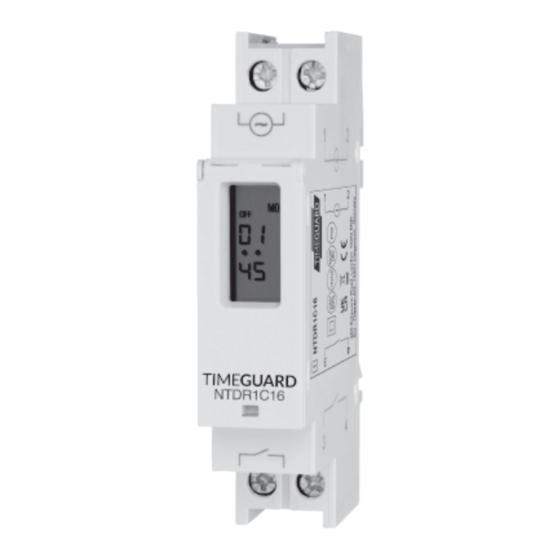
16A Single Channel DIN Rail
Digital Timer (Single Module)
Model: NTDR1C16
1. General Information
These instructions should be read carefully and retained for further reference
and maintenance.
Note: Timeguard reserve the right to alter these instructions at any time.
Up to date instructions will always be available for download at
www.timeguard.com
2. Safety
• Before installation or maintenance, ensure the mains supply to the timer is
switched off and the circuit supply fuses are removed or the circuit breaker
turned off.
• It is recommended that a qualified electrician is consulted or used for the
installation of this timer and install in accordance with the current IEE wiring
and Building Regulations.
• Check that the total load on the circuit including when this timer is
fitted does not exceed the rating of the circuit cable, fuse or circuit breaker.
• To clean use a clean dry cloth only. Do not use liquid cleaners.
3. Technical Specifications
• Mains Supply:
220-240V AC 50Hz
• Class Protection:
Class II
• IP Rating:
IP20
• Operating Temperature:
0˚ to 40˚C
• Switch Rating:
16A Resistive 2A Inductive at 230V AC
• Programmable Slots:
• Programmable Sequences:
• Manual Override:
• Time Deviation:
• Power Reserve:
• Installation Type:
• Terminal connections:
• Dimensions (H x W x D):
• Front Projection From DIN Rail:
• CE / UKCA Approved
60mm
55mm
4. Installation
• Ensure the mains supply is switched off and the circuit supply fuses are
removed or the circuit breaker turned off.
• Cover or shield any adjacent live components
• This timer is designed to be din rail mounted and as such should be Installed
in accordance with BS EN 60715.
• Terminate the 230V 50Hz supply and load cables to the terminal block
ensuring the correct polarity is observed and that all bare conductors are
sleeved. See section 5 Connection Diagram.
400W LED at 230V AC
Volt free switching
6 Programmes
Mon - Fri, Sat - Sun, Mon - Sat,
Mon - Sun or individual days
Yes
2 seconds per day
Up to 1000 hours
DIN Rail mount
2.5mm² max
90mm x 18mm x 60mm
55mm
18mm
1
2
~
ON
MON
08
• •
00
90mm
3
4
5. Connection Diagram
NTDR1C16 230V 50Hz Mains Switching
230V 50Hz Mains Supply
1
2
Live (Brown or Red) to
Neutral (Blue or Black) to
~
Load
Live In (Brown or Red) to
ON
MON
08
Switched Live
• •
00
(Brown or Red to
Neutral (Blue or Black) will join the
load from the 230V 50Hz mains
circuit as shown on the diagram.
3
4
N
L
NTDR1C16 Volt Free Switching
230V 50Hz Mains Supply
1
2
Live (Brown or Red) to
Neutral (Blue or Black) to
~
Load
Common (Volt Free Input) Terminal 3
ON
MON
08
Volt Free Output to
• •
00
3
4
N
L
L (Volt Free Input: Supply)
Volt Free Circuit
6. Battery
• The time switch has a factory fitted rechargeable battery to give clock
operation and programme memory back up during loss of mains supply.
• Before programming for the first time, connect the unit to the mains supply
for at least 15 minutes. Prior to programming, press the reset button
marked as "R" on the unit.
• If the display is not visible or very faint, charge for 4 hours prior to pressing
the reset "R" button and programming.
• The NTDR1C16 has a battery reserve of up to 1000 hours.
7. Button Controls
• Please take note of the button controls for the timer for the next stages of setting
up the unit.
OFF
07
• •
45
Day Button: cycle day options for
programming and clock setting.
Day
Timer
Timer Button: enter programming
R
mode and cycling through
programmes.
Timer Button: enter programming
mode and cycling through
programmes.
Terminal 1
Terminal 2
Terminal 3
Terminal 4
Terminal 1
Terminal 2
Terminal 4
MON
Hour Button: cycle hours for
programming and clock setting.
h+
m+
Minutes Button: cycle minutes for
programming and clock setting.
Manual Override Button: switches
connected load ON/OFF manually
Advertisement

Related Manuals for Timeguard NTDR1C16


Summary of Contents for Timeguard NTDR1C16
- Page 1 “R” button and programming. • Dimensions (H x W x D): 90mm x 18mm x 60mm • The NTDR1C16 has a battery reserve of up to 1000 hours. • Front Projection From DIN Rail: 55mm • CE / UKCA Approved 7.
- Page 2 • Once you have set the hour for which programme 1 OFF will operate, press (where agreed by Timeguard), the customer is responsible for all shipping and the minute button. The display will now have “00” on screen where the postal charges outside of the UK.
Need help?
Do you have a question about the NTDR1C16 and is the answer not in the manual?
Questions and answers