Table of Contents
Advertisement
Available languages
Available languages
Quick Links
RD ATEX
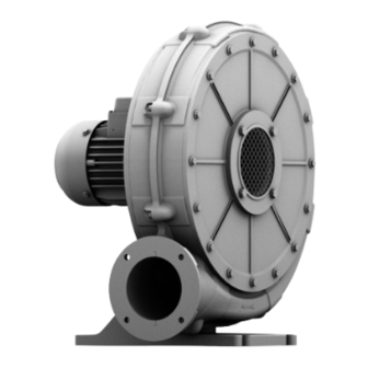
Mitteldruckventilator
Betriebs- und Montageanleitung
DE
Middle pressure blower
Operating and assembly instructions
EN
Ventilateurs moyenne pression
Instructions de service et de montage
FR
Wentylatory średniociśnieniowe
Instrukcja obsługi i montażu
PL
RD 0, RE 0, RD 10, RE 10, RD 14, RD 16, RE 16, RD 2, RE 2, RD 4, RE 4, RD 5, RE 5,
RD 6, RE 6, RD 62, RD 64, RD 65, RD 7, RD 72, RD 74, RD 8, RD 82, RD 84, RD 92, RD 94
www.elektror.com
Advertisement
Chapters
Table of Contents

Subscribe to Our Youtube Channel
Related Manuals for Elektror RD ATEX


Summary of Contents for Elektror RD ATEX
- Page 1 RD ATEX Mitteldruckventilator Betriebs- und Montageanleitung Middle pressure blower Operating and assembly instructions Ventilateurs moyenne pression Instructions de service et de montage Wentylatory średniociśnieniowe Instrukcja obsługi i montażu RD 0, RE 0, RD 10, RE 10, RD 14, RD 16, RE 16, RD 2, RE 2, RD 4, RE 4, RD 5, RE 5, RD 6, RE 6, RD 62, RD 64, RD 65, RD 7, RD 72, RD 74, RD 8, RD 82, RD 84, RD 92, RD 94 www.elektror.com...
-
Page 2: Table Of Contents
Betriebs- und Montageanleitung RD ATEX Im Folgenden werden die Geräte-Kategorien nach ATEX INHALT aufgeführt: ANGABEN ÜBER DIE MASCHINE Kategorie 3G INFORMATIONEN ÜBER TRANSPORT Konstruktive Gerätegestaltung zur Vermeidung von Zünd- UND HANDHABUNG quellen bei Normalbetrieb mit Explosionsgefahr durch Gas (G). INFORMATIONEN ÜBER DIE INBETRIEBNAHME... - Page 3 Betriebs- und Montageanleitung RD ATEX Einbauart D Einbaulage mit horizontaler Motorwelle: Hinweis! Ventilator ist saug- und druckseitig angeschlossen Die Einbaulage mit horizontaler Motorwelle ist die Empfehlung des Herstellers. Nicht abgedichteter Abgedichteter Ventilator Ventilator ohne Innerhalb, wie außerhalb mit Fuß mit Konsole Innerhalb, wie außerhalb...
- Page 4 Das Fördermedium und die Umgebung enthalten keine von dieser Betriebs- und Montageanleitung ab. materialangreifenden Bestandteile, wie z.B. Säuren, Elektror-Ventilatoren zeichnen sich durch ein hohes Maß an Laugen, Lösungsmittel, Flugrost, Eisenoxide, aggressive Betriebssicherheit aus. Da es sich bei den Ventilatoren um oder abrasive Gase, Flüssigkeiten oder Feststoff...
- Page 5 In diesem Fall, wie auch Bei ATEX-Geräten mit Ex eb-Motor ist der thermische Mo- bei sonstiger Havarie, muss es ELEKTROR zur torschutz mit Kaltleiterfühlern zur direkten Temperaturüber- eingehenden Untersuchung zugänglich gemacht / wachung nur zusätzlich zum Überstromschutz zulässig (auf zugesandt werden.
-
Page 6: Informationen Über Transport
Betriebs- und Montageanleitung RD ATEX 3.2 Aufstellen, Montage 2 INFORMATIONEN ÜBER TRANSPORT • Bei Aufstellung, Montage und im anschließenden Betrieb UND HANDHABUNG DER MASCHINE keinen Schwing- oder Stoßbelastungen aussetzen. • Off ene Ansaug- oder Ausblasstutzen mit Schutzgittern 2.1 Transport und Handhabung nach DIN EN ISO 13857 abdecken. - Page 7 Betriebs- und Montageanleitung RD ATEX • Bei besonderen Umgebungsbedingungen bei denen es zu Maximalfrequenz Mindestfrequenz einer starken Verschmutzung des Ventilators und der (siehe Leistungsschild) Kühlrippen des Motors kommt, ist eine regelmäßige Kon- 50 Hz 5 Hz trolle der Geräte erforderlich.
-
Page 8: Angaben Zu Betrieb Und Verwendung
Betriebs- und Montageanleitung RD ATEX • Im unteren Frequenzbereich darf keine spezielle Span- Nach Schutzabschaltungen wie z.B. Auslösen des Motor- nungsanhebung (Boost) erfolgen, da sich die Wicklung schutzschalters, Ansprechen des PTC-Auswertegerätes bei bei geringer Kühlleistung des Lüfterfl ügels stark Motoren mit Kalteiterfühler oder Schutzabschaltung des erwärmen kann. -
Page 9: Angaben Zur Instandhaltung
Es ist empfehlenswert, diese 5.1 Grundlegende Hinweise Dokumentation in einem Betriebsbuch vorzunehmen und Vor und nach einer Wartungs-/Instandhaltungsmaßnahme, dieses sicher zu verwahren. Reparatur oder Austausch von Bauteilen darf ein Elektror- ATEX-Ventilator nur bestimmungsgemäß eingesetzt werden 5.3 Kugellager (siehe 1.1). Gefahr! Stellen Sie vor Beginn jeder Wartungs-/Instandhaltungsmaß-... -
Page 10: Sicherheitsrelevante Informationen Über Ausserbetriebnahme Und Abbau
überprüfen. D.h. die Durchlässigkeit der Filter ist vom Betreiber zu gewährleisten. Diese Servicepartner verfügen über ein bestehendes Ver- tragsverhältnis mit Elektror und sind auf die Instandsetzung 5.6 ATEX-Laufrad unserer ATEX-Ventilatoren geschult. Die Einhaltung der Der Wuchtzustand, sowie Plan- und Radialschlag des Laufra- EU-weit geltenden ATEX-Vorschriften, aber auch der spezi- des dürfen sich in Folge Wartung/Instandhaltung, einer Repara-... - Page 11 HAFTUNGSAUSSCHLUSS Die Verantwortung für die bestimmungsgemäße Verwen- dung des Gerätes trägt der Betreiber. Die Fa. Elektror lehnt jede Haftung für nicht bestimmungsge- mäßen Gebrauch ihrer Geräte und Komponenten ab. Dies gilt insbesondere auch für besondere Verwendungen und Einsatzbedingungen, die nicht ausdrücklich mit der Fa.
- Page 12 Explosionsgefährdete Bereiche Teil 7: Geräteschutz durch erhöhte Sicherheit „e“ Die Elektror airsystems gmbh als Hersteller verpfl ichtet sich, die speziellen Unterlagen zu dieser unvollständigen Maschine einzelstaatlichen Stellen auf Verlangen elektronisch oder in Papier-Form zu übermitteln. Die zu dieser unvollständigen Maschine gehörenden speziellen technischen Unterlagen nach Anhang VII Teil B wurden erstellt und bei der „notifi zierten Stelle“...
- Page 13 www.elektror.com...
- Page 14 Explosion group Explosion group Explosion group IIIC 1.1 Designated use The operation of an explosion-protected Elektror blower, in Available Available On request accordance with the 2014/34/EU directive, is only permitted in countries or in economic sectors where this directive is Installation type B or C valid or is not restricted, as well as legally recognised.
- Page 15 Operating and assembly instructions RD ATEX Installation type D Installation position with a horizontal motor shaft: Note! Fan is connected on the intake and pressure side The motor shaft with a horizontal motor shaft is recommended by the manufacturer. Sealed fan...
- Page 16 Operating and Assembly Instructions. • Equipment categories 2G and 3G: Elektror blowers off er a high level of operational reliability. The fl ow medium and the area surrounding the blower As the blowers are high-powered machines, the safety in-...
- Page 17 To ensure this, the trip time of the monitoring device needs to event of other serious incidents, the equipment be shorter for the start-up current ratio I than the heat-up must be made accessible / sent to Elektror for im- time t for the respective temperature class. mediate examination.
- Page 18 Operating and assembly instructions RD ATEX Note! Start-up The eye bolt on the motor must not be used to lift Alarm 11,8 the entire blower. This is used if the motor needs to be (dis)assembled. Shut-down 12,5 2.2 Storage 3.3 Electrical connection •...
- Page 19 Operating and assembly instructions RD ATEX • If a motor fi lter is included in the scope of supply, it must with shielded cables. be installed in accordance with the specifi cations in the • Connect the shielding braid of all cables con- assembly instructions of the converter/motor fi...
-
Page 20: Instructions For Operation And Use
Before and after maintenance/service measures, repairs or resistance is too low (excessive current consumption). The replacement of parts, an Elektror ATEX blower may only be volumetric air fl ow should be reduced in this case by means employed as intended (see 1.1). - Page 21 The equipotential bonding must be inspected in conjunction duration of storage of the Elektror product. Type-related in- with every maintenance job and shall be in good operating formation can be acquired from Elektror Product manage- order after the maintenance job is completed.
-
Page 22: Safety-Related Information On Taking Out Of Operation And Removal
When using spare parts and accessories for explosion pro- The disconnection of all electrical connections and any tected blowers made by Elektror, be sure to apply and ad- other electrical work in connection with decommissioning here to the EU regulations or applicable national regulations must only be carried out by a qualifi... -
Page 23: Declaration Of Conformity
Part 7: Equipment protection by increased safety “e” As manufacturer, Elektror airsystems undertakes to forward the special technical documentation in respect of the partially completed machine to national authorities at their request. The special technical documentation in respect of this partially completed machine according to Appendix VII Part B has been created and is lodged with the “notifi... - Page 24 www.elektror.com...
- Page 25 www.elektror.com...
-
Page 26: Designated Use
Instructions de service et de montage RD ATEX dans lesquels cette directive est en vigueur ou reconnue juri- SOMMAIRE diquement sans restrictions. Il n’est pas permis de transformer ni de modifi er le ventilateur INDICATIONS CONCERNANT LA MACHINE mis en circulation. - Page 27 Instructions de service et de montage RD ATEX Groupes d’explosion 1.2 Positions d’installation conformes Les ventilateurs ATEX suivants sont disponibles dans les • L’installation des ventilateurs est autorisée uniquement groupes d’explosion suivants: en intérieur. L’installation extérieure n’est autorisée qu’avec une protection contre les intempéries adaptée Groupe d’explo-...
- Page 28 Les risques d’ordre mécanique présentés par les ventila- protection Ex eb sont destinés exclusivement au fonction- teurs Elektror sont minimes en raison de l’état de la tech- nement sur réseau à tension assignée ± 5% et fréquence nique et des règles de sécurité et de protection de la santé.
- Page 29 Instructions de service et de montage RD ATEX 1.5 Risque dû à une intervention dans la machine et à Cette diff érence de température peut atteindre une plage une mise en marche imprévue allant jusqu’à +20 °C selon les conditions de fonctionnement et le modèle.
-
Page 30: Informations Sur La Mise En Service
Instructions de service et de montage RD ATEX Les ventilateurs sont construits de sorte à éviter les réso- -> au sec, à l’abri de la poussière et des vibrations nances à une vitesse de fonctionnement constante. • Plage de température pour le stockage comprise entre Lorsque le ventilateur fonctionne avec un convertisseur de -20 °C et +60 °C. - Page 31 Instructions de service et de montage RD ATEX 3.3 Branchement électrique • Le câble d’évaluation du moteur et du CTP entre le moteur et la sortie du convertisseur de fré- Remarque! quence doit être branché avec des câbles blindés. Les travaux décrits dans ce paragraphe doivent être eff...
-
Page 32: Indications Sur Le Fonctionnement Et L'utilisation
Instructions de service et de montage RD ATEX Avis! 11,1 kW < Puissance du En cas de livraison d’un pack de variateur de moteur <= 30,0 kW fréquence, ce dernier ne convient pas pour l’installation et le fonctionnement dans un Les temps d’accélération et de décélération doivent être uni-... -
Page 33: Indications Sur L'entretien
Celle-ci dépend du type de 5 INDICATIONS SUR L’ENTRETIEN palier et d’appareil ainsi que des conditions de stockage et de la durée de stockage du produit Elektror. Service de 5.1 Remarques fondamentales gestion des produits Elektror fournira des renseignements Avant et après toute intervention pour des raisons d’entre-... - Page 34 Instructions de service et de montage RD ATEX servation de la réglementation et des indications du fabri- vaux elle doit être en parfait état. Les mesures réalisées ne cant doivent être documentées. Pour la documentation, doivent en aucun cas provoquer un transfert à la zone explo- nous vous recommandons de tenir un journal de service sible.
-
Page 35: Informations Relatives A La Securite Lors De La Mise Hors Service Et Du Demontage
ATEX et par conséquent ne sont pas valables. Recommandation : La mise en oeuvre des pièces de re- change d’origine de la Sté Elektror vous permet de réduire le risque le plus possible. 6 INFORMATIONS RELATIVES A LA... - Page 36 Partie 7 : protection du matériel par sécurité augmentée « e » La société Elektror airsystems gmbh, en tant que fabricant, s’engage à transmettre sur demande et au format électronique ou papier les documents spécifi ques relatifs à cette machine incomplète aux organismes publics. Les documents techniques spécifi ques selon l’annexe VII Partie B relatifs à...
- Page 37 www.elektror.com...
- Page 38 Urządzenia elektryczne przeznaczone do użytku w miejscach 1.1 Użytkowanie zgodnie z przeznaczeniem nie zagrożonych wybuchem metanu (innych niż górnictwo). Eksploatacja wentylatora fi rmy Elektror w wykonaniu prze- ciwwybuchowym zgodnie z dyrektywą 2014/34/EU dozwo- Grupy wybuchowości lona jest tylko w krajach lub obszarach gospodarczych, w Poniższe wentylatory ATEX znajdują...
- Page 39 Instrukcja obsługi i montażu RD ATEX Minimalny odstęp obudowy wentylatora (dla wlotu zim- Grupa wybucho- Grupa wybucho- Grupa wybucho- nego powietrza) wości IIB wości IIIC wości IIC Minimalny odstęp od obudowy Dostępny Dostępny Na zamówienie wentylatora Moc napędowa [mm] [cale] Typ zabudowy B lub C ≤...
- Page 40 Instrukcja obsługi i montażu RD ATEX Temperatury i warunki otoczenia Użytkowanie zgodnie z przeznaczeniem wyklucza: • Szczególne warunki otoczenia takie jak np.: temperatura maks. tempera- otoczenia w miejscu montażu/eksploatacji przekraczająca min. temperatura tura +40 °C, osadzanie pyłu, wstrząsy w miejscu montażu/eks- ploatacji wentylatora.
- Page 41 Instrukcja obsługi i montażu RD ATEX 1.7 Zasysanie stu temperatury t dla poszczególnych klas temperaturo- wych oraz krotność prądu rozruchowego I podane są na Ostrzeżenie! tabliczce znamionowej lub tabliczce dodatkowej silnika. Ryzyko obrażeń spowodowane działaniem W przypadku zespołów ATEX z silnikiem Ex eb termiczny ssącym!
- Page 42 Instrukcja obsługi i montażu RD ATEX Środki, które muszą być podjęte w przypadku zapalenia/ nel techniczny o odpowiednich kwalifi kacjach i uprawni- wybuchu lub innego typu awarii: eniach. Eksploatacja po wadliwym montażu, konser- wacji lub nieuzgodnionej wymianie części skutkuje Jeśli w otoczeniu zespołu lub w jego wnętrzu użytkowaniem niezgodnym z przeznaczeniem i powoduje...
- Page 43 Instrukcja obsługi i montażu RD ATEX • Przyłącze przewodu ochronnego znajduje się w skrzynce • Informacje na temat instalacji zgodnej z zasadami kompa- zaciskowej. tybilności elektromagnetycznej i montażu falownika poda- ne są w dokumentacji dostawcy. • Należy przestrzegać dodatkowych informacji producenta silnika i falownika, które znajdują...
- Page 44 Instrukcja obsługi i montażu RD ATEX 3.3.4 Szczególne wskazówki dotyczące podłączania Kontrola kierunku wirowania i uruchamiania wentylatora / silnika napędowego Włączyć wentylator. Kierunek wirowania wirnika musi być do pracy z przemiennikiem częstotliwości zgodny ze strzałką umieszczoną na obudowie. W przypadku błędnego kierunku wirowania należy zamienić...
- Page 45 Jest to uwarunkowane typem łożysk oraz ty- pem urządzenia, a także warunkami i okresem składowa- nia produktu fi rmy Elektror. Informacji na ten temat doty- 5 INFORMACJE O KONSERWACJI czących określonego typu udziela dział wsparcia technicz- nego dział...
- Page 46 Oznacza to, że użytkownik Tego typu partnerzy serwisowi posiadają aktualny stosunek musi zapewnić przepustowość fi ltrów. umowy z fi rmą Elektror i są przeszkoleni w zakresie napraw naszych wentylatorów ATEX. Nasi kontrahenci serwisowi 5.6 Wirnik ATEX dokładnie przestrzegają zarówno przepisów ATEX obowią- Wyważenie oraz bicie czołowe i promieniowe wirnika nie...
- Page 47 Firma Elektror nie ponosi również odpowiedzialności za zaniedbane prace konserwacyjne i naprawy, prace konser- wacyjne i naprawy przeprowadzone nieprawidłowo, z opóź- nieniem lub przeprowadzone przez inne osoby niż personel techniczny fi rmy Elektror oraz za możliwe skutki takiego po- stępowania. www.elektror.com...
- Page 48 Przestrzeniach zagrożonych wybuchem część 7: Zabezpieczenie urządzeń za pomocą budowy wzmocnionej „e” Firma Elektror airsystems gmbh jako producent zobowiązuje się do przekazania na żądanie urzędom państwowym specjalnych dokumentów w formie elektronicznej lub papierowej dotyczących niniejszej maszyny nieukończonej. Specjalna dokumentacja techniczna dotycząca niniejszej maszyny nieukończonej została sporządzona według załącznika VII część B i została złożona w „podanej instytucji”, oznacz.
- Page 49 www.elektror.com...
- Page 50 www.elektror.com...
- Page 51 www.elektror.com...
- Page 52 Elektror airsystems gmbh Hellmuth-Hirth-Str. 2 73760 Ostfi ldern Postfach 1252, 73748 Ostfi ldern Telefon: +49 711 31973-0 Telefax: +49 711 31973-5000 info@elektror.de www.elektror.com...
Need help?
Do you have a question about the RD ATEX and is the answer not in the manual?
Questions and answers