
Related Manuals for Clarke 6014011


Summary of Contents for Clarke 6014011
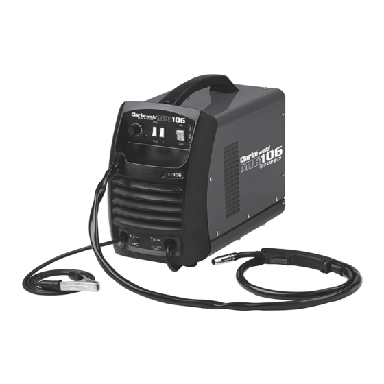
- Page 1 WARNING: Read these instructions before using the machine The welder is supplied set up for no gas welding NO GAS/GAS MIG WELDER MODEL NO: MIG 106 PART NO: 6014011 OPERATION & MAINTENANCE INSTRUCTIONS LS1018 - ISS 1...
-
Page 2: Introduction
GUARANTEE This CLARKE product is guaranteed against faulty manufacture for a period of 12 months from the date of purchase. Please keep your receipt as proof of purchase. -
Page 3: Accessories
1.0 mm (pack of 5) 8132275 A Gas regulator, Arc Activated Headshields, Anti-spatter Spray, Swan Necks, Torch Shrouds and Torch Liner are also available from your CLARKE dealer or our parts division. Parts & Service: 020 8988 7400 / E-mail: Parts@clarkeinternational.com or Service@clarkeinternational.com... -
Page 4: Table Of Contents
CONTENTS INTRODUCTION ............... 2 GUARANTEE ..............2 ENVIRONMENTAL RECYCLING POLICY ......2 ACCESSORIES ..............3 CONTENTS ............... 4 GENERAL SAFETY INSTRUCTIONS ........5 ELECTRICAL CONNECTIONS .......... 8 SAFETY SYMBOLS ............9 UNPACKING ..............9 Opening The Side Panel ............10 Fitting the Gas bottle Holder .......... -
Page 5: General Safety Instructions
GENERAL SAFETY INSTRUCTIONS WARNING: WHEN USING ELECTRICAL TOOLS, BASIC SAFETY PRECAUTIONS SHOULD ALWAYS BE FOLLOWED TO REDUCE THE RISK OF FIRE, ELECTRIC SHOCK AND PERSONAL INJURY WARNING: READ ALL THESE INSTRUCTIONS BEFORE ATTEMPTING TO OPERATE THIS PRODUCT AND KEEP THESE INSTRUCTIONS IN A SAFE PLACE. ELECTRIC SHOCK the weld seam and when not in use is insulated for safety. - Page 6 substances likely to generate a • Do not weld in the vicinity of dangerous vapour. children or animals and ensure no one is looking before striking an • The welding arc can cause serious arc. burns. Avoid contact with skin. •...
- Page 7 If you have a when not in use and between problem with the machine contact operations. your local CLARKE dealer. • Take care that a build-up of gas is • NEVER use or store in a wet/damp not permitted to form in confined environment.
-
Page 8: Electrical Connections
ELECTRICAL CONNECTIONS WARNING: READ THESE ELECTRICAL SAFETY INSTRUCTIONS FULLY BEFORE CONNECTING THE PRODUCT TO THE MAINS SUPPLY. This product is provided with a standard 13 amp, 230 volt (50Hz), BS 1363 plug, for connection to a standard, domestic electrical supply. Should the plug need changing, make sure that a plug of identical specification is used. -
Page 9: Safety Symbols
Read Instruction manual before use. UNPACKING Any damage or deficiency should be reported to your CLARKE dealer immediately. Some of the components are stored within the machine side compartment. The components include the following: •... -
Page 10: Opening The Side Panel
OPENING THE SIDE PANEL WARNING: NEVER OPERATE THIS MACHINE WITH THE SIDE PANELS PARTIALLY OPENED OR COMPLETELY REMOVED IMPORTANT: Ensure that the welder is not connected to the mains supply. 1. Open the side panel, by pushing the latch down and allowing the side panel to drop down. -
Page 11: The Welding Shield
CAUTION: WHEN REPLACING THE GLASS PANELS, ONLY USE PARTS SUPPLIED BY CLARKE INTERNATIONAL. THE DARK PANEL IS A CERTIFIED, SPECIFIC OPTICAL CLASS AND SHOULD NOT BE EXCHANGED FOR ANY OTHER TYPE. -
Page 12: Overview
OVERVIEW DESCRIPTION NO DESCRIPTION Carry Handle Torch Hose Gas Connection Point Earth Clamp Control Panel Welding Mask Torch Chipping Hammer Parts & Service: 020 8988 7400 / E-mail: Parts@clarkeinternational.com or Service@clarkeinternational.com... -
Page 13: The Control Panel
THE CONTROL PANEL 1. Wire speed control knob. As a general rule, a higher current requires a higher wire speed. 2. Current setting switches MIN-MAX & 1-2. Used together these two switches provide 4 increasing power levels as follows: • MIN-1 •... -
Page 14: Preparation For Use
MOUNTING THE WELDING WIRE SPOOL WARNING: MAKE SURE THAT THE WELDER IS NOT CONNECTED TO THE MAINS SUPPLY. NOTE: Spools of welding wire are available from your Clarke Dealer. 1. Open the side panel by pushing the latch down and allowing the side panel to open. -
Page 15: Threading The Wire
5. Pull the roller off the drive spindle. • The groove size is stamped on the corresponding side of the roller. Select the groove size according to the size of the wire you are using and put the roller back on the spindle with your chosen side facing you. - Page 16 6. Close the side panel of the welder. 7. Pull off the torch shroud with a twisting movement, then unscrew the contact tip. 8. Connect the welder to the power supply and switch ON. 9. Set the ‘WIRE FEED’ rotary control on the front panel to position 7 or 8 and squeeze the trigger on the torch body.
-
Page 17: Mig Welding Principles
MIG WELDING PRINCIPLES MIG (Metal Inert Gas) welding allows you to fuse together two similar metals without altering the properties of the metal. A consumable wire electrode is continuously fed through the welding torch that is fitted with a concentric gas nozzle. the wire is connected to a high voltage supply which creates an electric arc between the electrode (the wire) and the workpiece. -
Page 18: Welding Without Gas
WELDING WITHOUT GAS 1. If using 0.9mm flux cored wire, connect the terminal as shown. • The earth cable (Thicker Lead) should be connected to the positive (Red) terminal. • The cable from torch (Thinner Lead) should be connected to the Negative (Black) terminal. -
Page 19: Operation
OPERATION CAUTION: THE DUTY CYCLE MUST BE ADHERED IN ORDER TO PREVENT THE THERMAL OVERLOAD PROTECTION FROM ACTIVATING 1. With the welding current set and the wire trimmed, set the wire feed control to 6. 2. Plug the machine into the mains supply and switch on the machine. 3. -
Page 20: Thermal Overload
THERMAL OVERLOAD The ‘Thermal Overload’ shuts off the welder when it becomes too hot, due to the duty cycle being exceeded. This is to prevent any damage to the machine. When this occurs, the warning lamp shown will light up. Allow the welder to cool, until the amber light extinguishes before resuming work. -
Page 21: Maintenance
Check the hose for security and damage. As a general rule the power supply should be inspected at least annually. Consult your CLARKE dealer for advice if necessary. Wire feed unit: The feed roller wire guide plays an important part in obtaining consistent results. -
Page 22: Rating Plate
RATING PLATE Name and address of manufacturer Load Voltage symbol Model number, part number Energy Input symbol Batch number Rated supply voltage Single phase transformer-rectifier Rated maximum supply current British Standards applied Maximum effective supply current Welding process This symbol indicates that the unit is suitable for carrying out welding operations in an environment which has an increased risk of electric... -
Page 23: Specifications
Rated Max Input Current (A) Welding Capacity (Mild Steel) 4 mm (maximum) CLARKE International reserve the right to change specifications at any time without prior notice. DUTY CYCLE The duty cycle determines the machine ‘down time’. i.e 10% means 1 minutes operation followed by 9 minutes of rest. -
Page 24: Arc Activated Headshields
ARC ACTIVATED HEADSHIELDS These highly popular headshields activate instantly when the arc is struck and allow you to have both hands free when welding,. Model Grinding Solar Fixed Flip Up Part Number Activated function Powered Shade ✔ ✔ ✔ GWH4 6000706 ✔... -
Page 25: Troubleshooting
TROUBLESHOOTING Your CLARKE MIG Welder has been designed to give long and trouble free service. If, however, having followed the instructions in this booklet carefully, you still encounter problems, the following points should help identify and resolve them. PROBLEM CAUSE... - Page 26 If you have any problems which cannot be resolved by reference to the above, or if you require spare parts for your welder please contact your local Clarke dealer. Parts & Service: 020 8988 7400 / E-mail: Parts@clarkeinternational.com or Service@clarkeinternational.com...
-
Page 27: Declaration Of Conformity
DECLARATION OF CONFORMITY Parts & Service: 020 8988 7400 / E-mail: Parts@clarkeinternational.com or Service@clarkeinternational.com...
Need help?
Do you have a question about the 6014011 and is the answer not in the manual?
Questions and answers