
Subscribe to Our Youtube Channel
Related Manuals for Clarke IMIG100NG


Summary of Contents for Clarke IMIG100NG
- Page 1 NO GAS INVERTER MIG WELDER MODEL NO: IMIG100NG PART NO: 6015610 OPERATION & MAINTENANCE INSTRUCTIONS ORIGINAL INSTRUCTIONS GC02/22...
-
Page 2: Mig Welding Principles
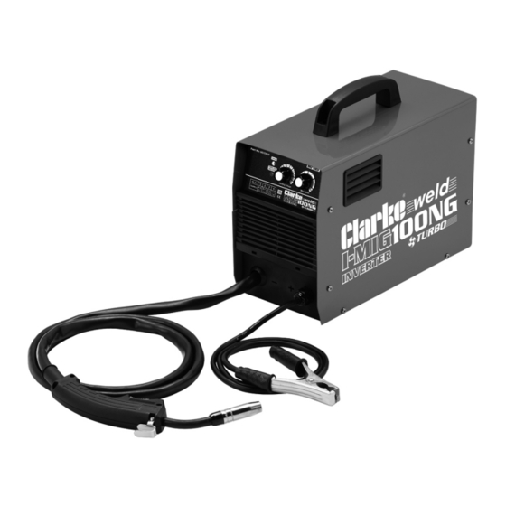
INTRODUCTION Thank you for purchasing this CLARKE Welder. The IMIG100NG inverter welder is for light duty manual arc welding only. It has been designed specifically for continuous welding of carbon or mild steels up to 4mm without protective gas using appropriate 0.9mm flux cored electrode wire. The welder is designed for domestic use only and not intended for commercial or trade use. -
Page 3: General Precautions
SAFETY PRECAUTIONS FOR ALL TYPES OF WELDING WARNING: AS WITH ALL MACHINERY, THERE ARE CERTAIN HAZARDS INVOLVED WITH THEIR OPERATION AND USE. EXERCISING RESPECT AND CAUTION WILL CONSIDERABLY LESSEN THE RISK OF PERSONAL INJURY. HOWEVER, IF NORMAL SAFETY PRECAUTIONS ARE OVERLOOKED, OR IGNORED, PERSONAL INJURY TO THE OPERATOR MAY RESULT. -
Page 4: Fire And Explosion Prevention
ethylene vapours to form phosgene. DO NOT WELD or cut where solvent vapours can be drawn into the welding or cutting atmosphere or where the radiant energy can penetrate to atmospheres containing even minute amounts of trichloroethylene or perchloroethylene. C) FIRE AND EXPLOSION PREVENTION Causes of fire and explosion are: 1. -
Page 5: Burn Protection
A container with unknown contents should be cleaned (see paragraph above). Do NOT depend on sense of smell or sight to determine if it is safe to weld or cut. Hollow castings or containers must be vented before welding or cutting as they can explode. -
Page 6: Shock Prevention
intensity gas-shielded arc) can cause a retinal burn that may leave a permanent dark area in the field of vision. Before welding whilst wearing contact lenses, seek advice from your optician. PROTECTION OF NEARBY PERSONNEL For production welding, a separate, well vented room or enclosed bay is best. In open areas, surround the operation with low reflective, non- combustible screens or panels. - Page 7 2) TORCH A fully insulated torch should be used without protruding screws or other damage. 3) CONNECTORS Fully insulated lock-type connectors should be used to join welding cable. 4) CABLES Frequently inspect cables for wear, cracks and damage. IMMEDIATELY REPLACE those with excessively worn or damaged insulation to avoid possibly lethal shock from bared cable.
-
Page 8: Preparation Of The Working Area
9. NEVER attempt any electrical or mechanical repair unless your are a qualified technician. If you have a problem with the machine contact your local CLARKE dealer. 10. NEVER continue to weld, if, at any time, you feel even the smallest electric shock. -
Page 9: Environmental Recycling Policy
14. NEVER allow the earth cable or torch hose to become wrapped around the operator or any person in the vicinity. A comprehensive range of CLARKE safety equipment for use when welding is available from your local dealer. Consideration should be given to shielding the supply cable of permanently installed welding equipment, in metallic conduit or equivalent. -
Page 10: Electrical Connections
ELECTRICAL CONNECTIONS WARNING: READ THESE ELECTRICAL SAFETY INSTRUCTIONS FULLY BEFORE CONNECTING THE PRODUCT TO THE MAINS SUPPLY. This product is provided with a standard 13 amp, 240 volt (50Hz), BS 1363 plug, for connection to a standard, domestic electrical supply. Should the plug need changing, make sure that a plug of identical specification is used. -
Page 11: Safety Symbols
SAFETY SYMBOLS The following safety warning symbols are displayed on the machine. Read instruction Danger! Arc rays manual before use. Recycle unwanted Danger! Harmful fumes materials in accordance with WEEE directive. Wear suitable welding Do not weld near gloves flammable or combustible materials Danger! Risk of electric shock. - Page 12 Copper Torch Tips - 2 x 0.9 mm, loose & 1 x 0.9 mm (fitted) When unpacking, any damage or deficiency should be reported to your CLARKE dealer immediately. Parts & Service: 020 8988 7400 / E-mail: Parts@clarkeinternational.com or Service@clarkeinternational.com...
-
Page 13: The Control Panel
PREPARATION FOR USE MOUNTING THE WELDING WIRE SPOOL Warning: Ensure that the welder is not connected to the mains supply. NOTE: Spools of welding wire are available from your CLARKE dealer. 1. Open the side panel. 2. Remove the retaining wingnut, washer and retaining disc. -
Page 14: Threading The Wire
• The spool must be fitted with the correct orientation otherwise it will not feed correctly. 4. Refit the retaining disc, washer and wingnut. THREADING THE WIRE IMPORTANT: DO NOT release the tension on the wire as it will unravel causing feeding problems later. - Page 15 7. Pull off the torch shroud with a twisting movement, (if a tight fit, some hand grips will be required) then unscrew the contact tip. 8. Connect the welder to the power supply and switch ON. 9. Set the ‘WIRE SPEED’ rotary control on the front panel to position 4 or 6 and squeeze the trigger on the torch body.
-
Page 16: Operating The Welder
OPERATING THE WELDER PREPARING THE WORKPIECE The area being welded should be perfectly clean. Any coating, plating or corrosion must be removed, otherwise a good weld will be impossible to achieve. Attach the earth clamp to the workpiece as close to the point of weld as possible, without it being intrusive. -
Page 17: Thermal Overload
The duty cycle determines the machine ‘down time’. i.e 10% means 1 minutes operation followed by 9 minutes of rest. The duty cycle must be adhered to prevent the thermal cutout protection from activating IMIG100NG Duty Cycle (%) Rated Welding Current (A) Conventional Load Voltage (V) 17.4... -
Page 18: Maintenance
Check the hose for security and damage. As a general rule the power supply should be inspected at least annually. Consult your CLARKE dealer for advice if necessary. Parts & Service: 020 8988 7400 / E-mail: Parts@clarkeinternational.com or Service@clarkeinternational.com... - Page 19 To keep the contact tip free from spatter, we recommend the use of anti- spatter spray (6000715) available from your CLARKE dealer. Torch Shroud The torch shroud must also be kept clean and free from spatter. Build-up of spatter inside the gas cup can cause a short circuit at the contact tip which will result in expensive machine repairs.
-
Page 20: Troubleshooting
TROUBLESHOOTING Your CLARKE welder has been designed to give long and trouble free service. If however, having followed the instructions in this booklet carefully you still encounter problems the following points should help identify and resolve them. PROBLEM CAUSE SOLUTION... - Page 21 If you have any problems which cannot be resolved by reference to the above, or if you require spare parts for your welder please contact your local Clarke dealer. Parts & Service: 020 8988 7400 / E-mail: Parts@clarkeinternational.com or Service@clarkeinternational.com...
-
Page 22: Rating Plate
RATING PLATE Model number Rated Welding Current symbol Part number Load Voltage symbol Single phase transformer-rectifier Rated supply voltage British Standards applied Energy Input symbol Welding Current symbol - direct Degree of protection current. Welding process Rated maximum supply current Min + max welding current and Maximum effective supply corresponding load voltages... -
Page 23: Specifications
Duty cycle Welding wire diameter 0.9mm Spool capacity 1kg mini spool (max) Feed speed range 2-11M CLARKE International reserve the right to change specifications at any time without prior notice Parts & Service: 020 8988 7400 / E-mail: Parts@clarkeinternational.com or Service@clarkeinternational.com... - Page 24 CONSUMABLES The following are some of the accessories available from your CLARKE dealer. Please quote the part numbers shown below: Part Description Part No Welding Clamps 3-piece locking clamp set 1800103 Welding Magnets 2-piece clamp set for holding work still...
-
Page 25: Arc Activated Headshields
ARC ACTIVATED HEADSHIELDS These highly popular head shields activate instantly when the arc is struck and allow you to have both hands free when welding. Model Grinding Solar Fixed Flip Up Part Activated function Powered Shade Number ✔ ✔ ✔ GWH4 6000706 ✔... - Page 26 DECLARATION OF CONFORMITY-UK Parts & Service: 020 8988 7400 / E-mail: Parts@clarkeinternational.com or Service@clarkeinternational.com...
-
Page 27: Declaration Of Conformity-Eu
DECLARATION OF CONFORMITY-EU Parts & Service: 020 8988 7400 / E-mail: Parts@clarkeinternational.com or Service@clarkeinternational.com...
Need help?
Do you have a question about the IMIG100NG and is the answer not in the manual?
Questions and answers