Table of Contents
Advertisement
Quick Links
Advertisement
Table of Contents

Related Manuals for Clarke AT162


Summary of Contents for Clarke AT162
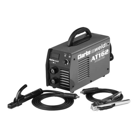
- Page 1 WARNING: A suitable welding headshield must be worn during use WARNING: Read these instructions before using the machine ARC TIG/MMA WELDER MODEL NO: AT162 PART NO: 6012145 OPERATION & MAINTENANCE INSTRUCTIONS ORIGINAL INSTRUCTIONS DL0821 - REV 3...
- Page 2 The AT162 is designed to be used for both metal ARC (MMA) and TIG welding (TIG welding leads are not supplied with the machine. These are however, readily available from your CLARKE dealer (Part number 6012233)).
-
Page 3: General Safety Instructions
GENERAL SAFETY INSTRUCTIONS WARNING: WHEN USING ELECTRICAL TOOLS, BASIC SAFETY PRECAUTIONS SHOULD ALWAYS BE FOLLOWED TO REDUCE THE RISK OF FIRE, ELECTRIC SHOCK AND PERSONAL INJURY. WARNING: READ ALL THESE INSTRUCTIONS BEFORE ATTEMPTING TO OPERATE THIS PRODUCT AND KEEP THESE INSTRUCTIONS IN A SAFE PLACE. ELECTRIC SHOCK •... -
Page 4: Personal Protection
FIRE OR EXPLOSION Welding can cause fires and explosions. Precautions should be taken to prevent these hazards. • Before starting work ensure the area is clear of flammable materials. • Move any combustible materials to a safe distance, especially substances likely to generate a dangerous vapour. -
Page 5: Protective Clothing
• NEVER attempt any electrical or mechanical repair unless your are a qualified technician. If you have a problem with the machine contact your local CLARKE dealer. • NEVER use or store in a wet/damp environment. DO NOT EXPOSE TO RAIN. -
Page 6: Safety Symbols
SAFETY SYMBOLS Read this instruction Do not expose to rain. booklet carefully before use. Wear eye protection Recycle unwanted materials instead of disposing of them as waste. All tools, accessories and Wear protective gloves packaging should be sorted, taken to a recycling centre and disposed of in a manner which is compatible... -
Page 7: Electrical Connections
ELECTRICAL CONNECTIONS CONNECTING TO MAINS NOTE: This tool is earthed and must only be connected to mains with an earth connection. Do not attempt to use it without an earth connection. • This welder is not supplied with a mains electrical plug because at full capacity it will draw far too much power for a normal domestic 230V mains plug and socket. -
Page 8: Mma/Arc Welding
MMA/ARC WELDING A consumable electrode is connected to a high amperage low voltage supply which creates an electric arc between the electrode and the workpiece. Benefits over TIG welding include, less experience needed, torch kit or shielding gas are not required. PREPARATION •... -
Page 9: Striking The Arc - Welding
5. Switch ON using the switch located on the rear panel. • The green light on the front panel should glow, indicating the machine is • If the machine stops at any time and the amber light comes ON, the thermal overload device has intervened. -
Page 10: Tig Welding
TIG WELDING TIG welding is primarily for very thin materials. It uses a non-consumable tungsten (or tungsten alloy) electrode, held in a torch. A shielding gas (100% Argon), is fed through the torch to protect: • The electrode, • Molten weld pool, •... -
Page 11: Tig Welding (Ref Fig.2)
TIG WELDING (REF FIG.2) • The machine is not equipped with a TIG welding torch and cables; these are available from your Clarke dealer (Part number 6012232). • Additionally, before TIG welding, you must obtain a gas cylinder of 100% pure Argon. - Page 12 8. Open the gas valve on the torch handle, • This will allow gas to flow from the torch nozzle. 9. Cover your face with the head shield, bring the torch to within 3-4mm of the work, and at an angle of 45°, so that the ceramic nozzle gently touches the work surface.
- Page 13 • Guidelines for the TIG welding current needed and recommended electrode sizes etc. for different gauges of material are shown in the chart below: Welding Workpiece Welding Filler Rod Gas Flow Metal Current Thickness Electrode Dia (mm) ltr/min (Amps) (mm) Dia (mm) Mild 20-30...
-
Page 14: Welding Pitfalls
WELDING PITFALLS The arc welding technique is an acquired skill and requires considerable practice before perfect results are obtained. The diagrams below will help to explain the pitfalls in your technique and how to overcome them. ARC TOO SHORT This causes irregular masses of weld to be deposited, with slag contamination on an uneven surface. -
Page 15: Troubleshooting
Spark will not start Bad clamp connection. Check clamp connection. Inverter printed circuit is Contact your nearest defective. CLARKE dealer. No output voltage Overheated machine (the Wait for thermal cutout to yellow LED should be on). be reset. Under-voltage/over-voltage Check the mains distribution limits exceeded. -
Page 16: Maintenance
DEFECT CAUSES SUGGESTIONS High Sprays Electrode is too inclined. Make appropriate corrections. Profile defects. Welding parameters are Follow basic and general incorrect. welding principles. Pass rate is not related to operating parameter requirements. Electrode not inclined constantly while welding. Arc is unstable. Insufficient current. -
Page 17: Rating Plate
RATING PLATE Name and address of Rated Welding Current Symbol manufacturer Model Number, / Part Number Conventional Load Voltage Symbol Serial / Batch Number Energy Supply Symbol Welding Power Source Rated Supply Voltage British Standards applied Rated Maximum Supply Current Welding Process Symbol Maximum Effective Supply Current... -
Page 18: Duty Cycle
DUTY CYCLE This welder is covered by regulations BS EN 60974-1:2012, where the Duty Cycle (X) is expressed as a percentage of time the machine may be used in a given period for a specified welding current. i.e. When welding at 100 Amps the machine may be used for 6 minutes (60%) in any10 minute period, Parts &... -
Page 19: Specifications
However, CLARKE International reserve the right to change specifications at any time without prior notice. ACCESSORIES The following are some of the accessories available from your CLARKE dealer. Please quote the part numbers shown below: DESCRIPTION... - Page 20 EXPLODED DIAGRAM & PARTS LIST AT162 Parts & Service: 020 8988 7400 / E-mail: Parts@clarkeinternational.com or Service@clarkeinternational.com...
- Page 21 DESCRIPTION NO DESCRIPTION Handle Inductance Top Housing Temi160 rectifier radiator Switch Fast recovery diode Cable Gland Control PCB Fan Hood Main PCB Power Cable Base Frame Rubber Foot Bridge Heatsink Quick connector ASM IGBT Radiator Knob Support bar Digital Display Rectifier bridge Shade IGBT...
- Page 22 DECLARATION OF CONFORMITY-UKCA Parts & Service: 020 8988 7400 / E-mail: Parts@clarkeinternational.com or Service@clarkeinternational.com...
-
Page 23: Declaration Of Conformity (Ce)
DECLARATION OF CONFORMITY-CE Parts & Service: 020 8988 7400 / E-mail: Parts@clarkeinternational.com or Service@clarkeinternational.com... - Page 24 Parts & Service: 020 8988 7400 / E-mail: Parts@clarkeinternational.com or Service@clarkeinternational.com...
Need help?
Do you have a question about the AT162 and is the answer not in the manual?
Questions and answers