
Subscribe to Our Youtube Channel
Related Manuals for Clarke weld MMA/TIG120


Summary of Contents for Clarke weld MMA/TIG120
- Page 1 MMA/TIG INVERTER WELDERS MODEL NO: MMA/TIG120, 160 & 200 PART NO: 6012100/6012101/6012102 OPERATION & MAINTENANCE INSTRUCTIONS ORIGINAL INSTRUCTIONS GC0722...
- Page 2 INTRODUCTION Thank you for purchasing this CLARKE Welder. Before attempting to operate the machine it is essential that you read this manual thoroughly and carefully follow all instructions given. In doing so you will ensure the safety of yourself and that of others around you, and you can also look forward to the welder giving you long and satisfactory service.
-
Page 3: Environmental Recycling Policy
ENVIRONMENTAL RECYCLING POLICY Through purchase of this product, the customer is taking on the obligation to deal with the WEEE in accordance with the WEEE regulations in relation to the treatment, recycling & recovery and environmentally sound disposal of the WEEE. In effect, this means that this product must not be disposed of with general household waste. - Page 4 TOXIC FUME PREVENTION Severe discomfort, illness or death can result from fumes, vapours, heat, or oxygen enrichment or depletion that welding (or cutting) may produce. Prevent them with adequate ventilation. NEVER ventilate with oxygen. Lead-, cadmium-, zinc-, mercury- and beryllium-, bearing materials, when welded (or cut) may produce harmful concentrations of toxic fumes.
-
Page 5: Electric Arc Welding
3. Openings (concealed or visible) in floors or walls can expose combustibles to sparks. 4. Combustibles adjacent to walls, ceilings, roofs or metal partitions can be ignited by radiant or conducted heat. After work, check that area is free of sparks, glowing embers and flames. An empty container that held combustibles or that can produce flammable or toxic vapours when heated, must never be welded on or cut, unless the container has first been cleaned. -
Page 6: Toxic Fume Prevention
EYE AND HEAD PROTECTION Protect eyes from exposure to arc. NEVER look at an electric arc without protection. Welding helmet or shield containing an appropriate filter plate (Please refer to the section ‘Welding Shield on page 12). Place over face before striking arc. - Page 7 PROTECTION AGAINST SHOCK Keep your body and clothing dry. Never work in damp area without adequate insulation against electric shock. Stay on a dry duckboard or rubber mat when dampness or sweat can not be avoided. Sweat, sea water, or moisture between body and an electrically LIVE part - or earthed metal - reduces the body surface electrical resistance, enabling dangerous and possibly lethal currents to flow through the body.
-
Page 8: Preparation Of The Working Area
6. NEVER attempt any electrical or mechanical repair unless your are a qualified technician. If you have a problem with the machine contact your local CLARKE dealer. 7. ALWAYS keep a fire extinguisher handy (Dry Powder, C02 or BCF, NOT Water). -
Page 9: Safety Symbols
A comprehensive range of CLARKE safety equipment for use when welding is available from your local dealer. See page 28. Consideration should be given to shielding the supply cable of permanently installed welding equipment, in metallic conduit or equivalent. Shielding should be electrically continuous throughout its length. - Page 10 ELECTRICAL CONNECTION (MMA/TIG120 ONLY) WARNING! READ THESE ELECTRICAL SAFETY INSTRUCTIONS THOROUGHLY BEFORE CONNECTING THE PRODUCT TO THE MAINS SUPPLY. Before switching the product on, make sure that the voltage of your electricity supply is the same as that indicated on the rating plate. This product is designed to operate on 230VAC 50Hz.
-
Page 11: Connecting To Mains Power
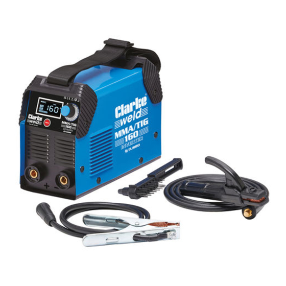
POWER CONNECTION FOR MMA/TIG160 & 200 CONNECTING TO MAINS POWER NOTE: These welders are earthed and must only be connected to the mains with an earth connection. DO NOT attempt to use it without one. • These welders will draw far too much power for a normal domestic 230V mains plug and socket and will be supplied fitted with a 32Amp, 3-pin industrial plug. - Page 12 OVERVIEW & INVENTORY The items supplied include the following: 1. 1 x MMA/TIG Inverter Welder 2. 1 x Electrode Holder 3. 1 x Earth Clamp & Cable 4. 1 x Combination Wire Brush / Hammer 5. 1 x Face Shield The welder is fitted with 6.
-
Page 13: Assembling The Welding Shield
• The clear glass panel should be replaced when it becomes badly pitted. 4. When replacing the glass panels, only use parts supplied by Clarke International. The dark panel is a certified, optical glass and should not be exchanged for any other type. -
Page 14: Preparation For Use
PREPARATION FOR USE FITTING THE WELDING ROD Select the appropriate welding rod and insert it into the welding rod holder. • It should be approximately the same thickness as the workpieces being welded. PREPARING THE WORKPIECE The area being welded should be perfectly clean. Any coating, plating or corrosion must be removed, otherwise a good weld will be impossible to achieve. - Page 15 • When the machine is on, the menu will display the size of the electrode fitting to the holder. The following sizes can be used and are available from your CLARKE dealer. MACHINE ROD DIAMETER WORKPIECE THICKNESS MMA/TIG120,160,200 1.6 mm...
- Page 16 5. Press the menu button to select MMA welding mode. • The current can be adjusted in this mode to match the material being welded. • To select the parameter use the menu to cycle between function. 6. Press the menu button to select Anti-Stick mode and switch it on or off by pressing the MENU control and turning the control...
-
Page 17: Voltage Reduction Device (Vrd)
VOLTAGE REDUCTION DEVICE (VRD) The VRD is a safety feature that It is also known as “Anti-shock”. It’s function is to lower the open circuit voltage across the output terminals to a safe 12V when the welder is not in use. As soon as the welder is used (a load of 200 ohms or less is detected), the voltage will increase to the full output... -
Page 18: Arc Welding
ARC WELDING WARNING: WHEN WELDING ALWAYS ENSURE THERE IS ADEQUATE VENTILATION IN THE WORK AREA AS THE WELDING PROCESS GIVES OFF TOXIC FUMES. WARNING: DO NOT STRIKE THE ELECTRODE ON THE WORKPIECE, AS THIS MAY DAMAGE THE ELECTRODE. WARNING: WELDING ARCS PRODUCE HARMFUL UV/IR LIGHT WHICH CAN SERIOUSLY DAMAGE YOUR EYES. -
Page 19: Tig Welding
3. At the finish of the weld, bring the end of the electrode backward in order to fill the weld crater and then quickly lift the electrode from the weld pool to extinguish the arc. 4. Inspect the job carefully. Any slag forming on the surface should be chipped away with a chipping hammer or pick. - Page 20 TIG WELDING • The machine is not equipped with a TIG welding torch and cables; these are available from your Clarke dealer (Part number 6012232). • Additionally, before TIG welding, you must obtain a gas cylinder of 100% pure Argon.
- Page 21 7. Switch ON using the switch mounted on the rear panel. The green light on the front panel will glow. 8. If the machine stops at any time and the amber light comes ON, the thermal overload has intervened. Wait until the welder has cooled sufficiently (the amber light goes out) before restarting work.
- Page 22 • The arc length generally varies between 3 and 6 mm depending on the type of joint, type and thickness of material and so on. • The torch is advanced in the direction of welding, without lateral movement, maintaining the torch angle of 45 to the workpiece.
-
Page 23: Welding Pitfalls
WELDING PITFALLS The arc welding technique is an acquired skill and requires considerable practice before perfect results are obtained. The diagrams below will help to explain the pitfalls in your technique and how to overcome them. ARC TOO SHORT This causes irregular masses of weld to be deposited, with slag contamination on an uneven surface. -
Page 24: Troubleshooting
Spark will not start Bad clamp connection. Check clamp connection. Inverter printed circuit is Contact your nearest defective. CLARKE dealer. No output voltage Overheated machine (the Wait for thermal cutout to red LED should be on). be reset. Internal relay has failed. -
Page 25: Care And Maintenance
DEFECT CAUSES SUGGESTIONS High Sprays Electrode is too inclined. Make appropriate corrections. Arc is unstable Insufficient current. Check condition of electrode and earth wire connection. Electrode melts Electrode core is not Replace electrode. obliquely centred. Connect two earth wires Magnetic blow to opposite sites of the phenomenon. -
Page 26: Rating Plate (Example)
RATING PLATE (EXAMPLE) Name/address of manufacturer Range of Output Model Number / Part Number Duty Cycle symbol Serial / Batch number Rated Welding Current symbol Welding Power Source Conventional Load Voltage symbol British Standards applied Energy Supply symbol Welding Process symbol Rated Supply Voltage Suitable for use in an Rated Maximum Supply Current... -
Page 27: Specifications
However, CLARKE International reserve the right to change specifications at any time without prior notice. GUARANTEE This CLARKE product is guaranteed against faulty manufacture for a period of 12 months from the date of purchase. Please keep your receipt as proof of purchase. -
Page 28: Arc Activated Headshields
CONSUMABLES The following are some of the accessories available from your CLARKE dealer. Please quote the part numbers shown below. DESCRIPTION PART NUMBER 1.6 x 300mm Arc Welding Rods 3050590 2.0 x 350mm Arc Welding Rods 3050592 2.5 x 350mm Arc Welding Rods 3050594 3.25 x 350mm Arc Welding Rods... -
Page 29: Component Parts
COMPONENT PARTS NO DESCRIPTION NO DESCRIPTION Shoulder strap assembly Insulated Gate Bipolar Transistors (1) Housing Insulated Gate Bipolar Transistors (2) Front plastic cover Rectifier bridge Front plate Transformer Adjusting knob Capacitors Digital Display Panel Relay Pos/Neg connection sockets Cooling fan assembly Base plate Fan grille Output connection... - Page 30 DECLARATION OF CONFORMITY -UK Parts & Service: 020 8988 7400 / E-mail: Parts@clarkeinternational.com or Service@clarkeinternational.com...
-
Page 31: Declaration Of Conformity (Ce)
DECLARATION OF CONFORMITY - CE Parts & Service: 020 8988 7400 / E-mail: Parts@clarkeinternational.com or Service@clarkeinternational.com...
Need help?
Do you have a question about the weld MMA/TIG120 and is the answer not in the manual?
Questions and answers