
Related Manuals for Clarke MMA200A


Summary of Contents for Clarke MMA200A
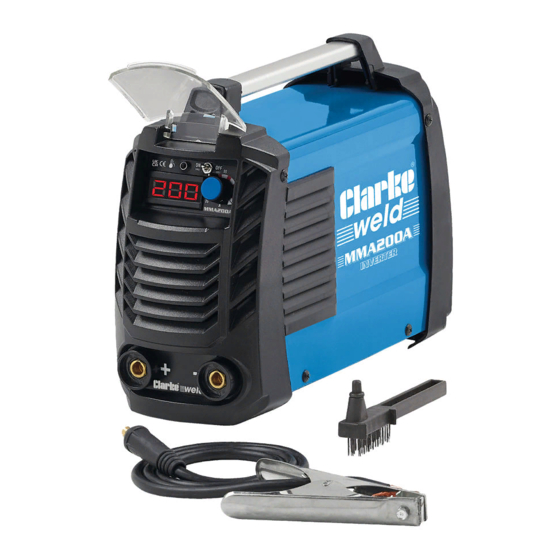
- Page 1 200A MMA INVERTER WELDER MODEL NO: MMA200A PART NO: 6012163 OPERATION & MAINTENANCE INSTRUCTIONS ORIGINAL INSTRUCTIONS GC1221...
- Page 2 INTRODUCTION Thank you for purchasing this CLARKE MMA (Arc) Welder. Before attempting to operate the machine it is essential that you read this manual thoroughly and carefully follow all instructions given. In doing so you will ensure the safety of yourself and that of others around you, and you can also look forward to the welder giving you long and satisfactory service.
- Page 3 SAFETY PRECAUTIONS FOR ALL TYPES OF WELDING WARNING: AS WITH ALL MACHINERY, THERE ARE CERTAIN HAZARDS INVOLVED WITH THEIR OPERATION AND USE. EXERCISING RESPECT AND CAUTION WILL CONSIDERABLY LESSEN THE RISK OF PERSONAL INJURY. HOWEVER, IF NORMAL SAFETY PRECAUTIONS ARE OVERLOOKED, OR IGNORED, PERSONAL INJURY TO THE OPERATOR MAY RESULT.
- Page 4 perchloroethylene vapours to form phosgene. DO NOT WELD where solvent vapours can be drawn into the welding atmosphere or where the radiant energy can penetrate to atmospheres containing even minute amounts of trichloroethylene or perchloroethylene. FIRE AND EXPLOSION PREVENTION Causes of fire and explosion are: 1.
-
Page 5: Electric Arc Welding
weld or cut. Hollow castings or containers must be vented before welding as they can explode. In explosive atmospheres, never weld or cut where the air may contain flammable dust, gas, or liquid vapours. ELECTRIC ARC WELDING Comply with precautions in above and this section. Arc welding, properly done, is a safe process but a careless operator invites trouble. -
Page 6: Shock Prevention
PROTECTION OF NEARBY PERSONNEL For production welding, a separate, well vented room or enclosed bay is best. In open areas, surround the operation with low reflective, non- combustible screens or panels. Allow for free air circulation, particularly at floor level. Provide face shields for all persons who will be looking directly at the weld. - Page 7 source is off. When installing, connect the frames of each unit such as welding power source, control, work table, and water circulator to the building earth. Conductors must be adequate to carry earth currents safely. Equipment made electrically LIVE by stray current may shock, possibly fatally. Do not EARTH to electrical conduit, or to a pipe carrying ANY gas or a flammable liquid such as oil or fuel.
-
Page 8: Preparation Of The Working Area
6. NEVER attempt any electrical or mechanical repair unless your are a qualified technician. If you have a problem with the machine contact your local CLARKE dealer. 7. ALWAYS keep a fire extinguisher handy (Dry Powder, C02 or BCF, NOT Water). -
Page 9: Safety Symbols
A comprehensive range of CLARKE safety equipment for use when welding is available from your local dealer. Consideration should be given to shielding the supply cable of permanently installed welding equipment, in metallic conduit or equivalent. Shielding should be electrically continuous throughout its length. -
Page 10: Electrical Connection
ELECTRICAL CONNECTION CONNECTING TO MAINS POWER NOTE: This welder is earthed and must only be connected to the mains with an earth connection. Do not attempt to use it without one. • This welder is not supplied with a mains electrical plug because at full capacity it will draw far too much power for a normal domestic 230V mains plug and socket. -
Page 11: Mma/Arc Welding
MMA/ARC WELDING PREPARATION To prepare the machine for ARC welding it is important that you follow the procedure below. 1. Making sure that the ON/OFF switch, located on the rear panel is in the OFF position, connect the welding leads as follows: •... -
Page 12: Vrd-Voltage Reduction Device
4. Switch ON using the switch located on the rear panel. • The display on the front panel will come on and show the current setting in amps. • If the machine stops at any time and the thermal overload indicator comes ON, the thermal overload device has intervened. - Page 13 STRIKING THE ARC - WELDING WARNING: WHEN WELDING ALWAYS ENSURE THERE IS ADEQUATE VENTILATION IN THE WORK AREA AS THE WELDING PROCESS GIVES OFF TOXIC FUMES. WARNING: WELDING ARCS PRODUCE HARMFUL UV/IR LIGHT WHICH CAN SERIOUSLY DAMAGE YOUR EYES. ALWAYS USE A WELDING HELMET WITH A SUITABLE FILTER THAT CONFORMS TO CURRENT STANDARDS.
-
Page 14: Welding Pitfalls
WELDING PITFALLS The arc welding technique is an acquired skill and requires considerable practice before perfect results are obtained. The diagrams below will help to explain the pitfalls in your technique and how to overcome them. ARC TOO SHORT This causes irregular masses of weld to be deposited, with slag contamination on an uneven surface. -
Page 15: Troubleshooting
Spark will not start Bad clamp connection. Check clamp connection. Inverter printed circuit is Contact your nearest defective. CLARKE dealer. No output voltage Overheated machine (the Wait for thermal cutout to red LED should be on). be reset. Internal relay has failed. - Page 16 DEFECT CAUSES SUGGESTIONS Profile defects Welding parameters are Follow basic and general incorrect. welding principles. Pass rate is not related to operating parameter requirements. Electrode not inclined constantly while welding. Arc is unstable Insufficient current. Check condition of electrode and earth wire connection.
-
Page 17: Maintenance
MAINTENANCE WARNING: DISCONNECT FROM MAINS BEFORE CLEANING. WARNING: DO NOT ATTEMPT TO CARRY OUT REPAIRS YOURSELF, UNLESS YOU ARE FULLY COMPETENT, ALL WORK MUST BE CARRIED OUT BY A QUALIFIED TECHNICIAN. The machine requires very little maintenance other than the following guidelines. -
Page 18: Rating Plate
RATING PLATE Name and address of manufacturer Rated Welding Current Symbol Model Number, / Part Number Conventional Load Voltage Symbol Serial / Batch Number Energy Supply Symbol Welding Power Source Rated Supply Voltage British Standards applied Rated Maximum Supply Current Welding Process Symbol Maximum Effective Supply Current This symbol indicates that the unit is... -
Page 19: Specifications
However, CLARKE International reserve the right to change specifications at any time without prior notice. GUARANTEE This CLARKE product is guaranteed against faulty manufacture for a period of 12 months from the date of purchase. Please keep your receipt as proof of purchase. -
Page 20: Arc Activated Headshields
CONSUMABLES The following are some of the accessories available from your CLARKE dealer. Please quote the part numbers shown below. DESCRIPTION PART NUMBER 2.5 mm Arc Welding Electrodes 3050584 3.2 mm Arc Welding Electrodes 3050586 4.0 mm Arc Welding Electrodes... -
Page 21: Component Parts
COMPONENT PARTS DESCRIPTION DESCRIPTION Front panel Printed circuit board Potentiometer Capacitor Indicator light Silicon bridge radiator Digital display Silicon bridge Plug IGBT radiator Gauge cover IGBT Handle Main transformer Cover Rectifier radiator Air Vent Rectifier tube Rear panel Driver transformer Machine base Control PCB Power switch... -
Page 22: Declarations Of Conformity
DECLARATIONS OF CONFORMITY Parts & Service: 020 8988 7400 / E-mail: Parts@clarkeinternational.com or Service@clarkeinternational.com... - Page 23 DECLARATIONS OF CONFORMITY Parts & Service: 020 8988 7400 / E-mail: Parts@clarkeinternational.com or Service@clarkeinternational.com...
Need help?
Do you have a question about the MMA200A and is the answer not in the manual?
Questions and answers