
Subscribe to Our Youtube Channel
Related Manuals for E-Mon Class 3200


Summary of Contents for E-Mon Class 3200
- Page 1 Test Equipment Depot - 800.517.8431 - 99 Washington Street Melrose, MA 02176 TestEquipmentDepot.com Class 3200 Meter ADVANCED KWH/DEMAND METER INSTALLATION INSTRUCTIONS 62-0390-02...
- Page 2 Before installing your new E-Mon product, please read the information on the following pages carefully. We believe that you will find the E-Mon D-Mon meters easy to install and to use for monitoring and evaluating your electrical usage.
-
Page 3: Table Of Contents
RS-232 Communications Section 6.9 Modem Wiring Section 6.10 Modbus RTU Wiring Section 6.11 BACnet MS/TP Wiring Section 6.12 Connecting Class 3200 Meters to USB Key using RS485 Section 6.13 Ethernet Communications Section 7.0 Multiple-Load Monitoring Section 8.0 Preventative/Scheduled Maintenance Section 9.0 Lithium Battery Replacement Section 10.0... -
Page 4: Introduction
MUST NOT be installed on service feeds of 277/480 volts or 347/600 and vice versa. Verify that the Class 3200 meter’s current sensors are sized suitably for the load to be monitored. Compare the color of the arrows on the current sensors to the chart below to confirm the correct current sensor is being used. - Page 5 WARNING Use of this instrument, the E-Mon D-Mon Class 3200 meter, in a manner inconsistent with this manual or not specified by the manufacturer in writing, can cause permanent damage to the unit and/or serious injury to the operator.
-
Page 6: Internal Electronic Assemblies
CLASS 3200 METER 2.0 INTERNAL ELECTRONIC ASSEMBLIES The units are comprised of two major subassembly boards, the main power board and the display board. Both circuit boards are mounted inside a UL Type 1 or Type 4X enclosure. MAIN DISPLAY... -
Page 7: Display Board
The display board connects to the main power board via a flex ribbon cable and the board mounts on the inside of the housing door. The Class 3200 meter features a 4-line LCD display that indicates multiple meter data points. -
Page 8: Meter Technical Specifications
Ordering Information: Define brand, class, input voltage, amperage, protocol, and sensor type in the format A-BB-CCC-DDDD-E-FFF-GGG, where A = Brand: E for E-Mon BB = designates Class: 3200 (32), 3400 (34), or 5000 (50) meter CCC = input voltage: (208, 480, 600, 120 volt for High Voltage) - Page 9 CLASS 3200 METER 3.0 METER TECHNICAL SPECIFICATIONS (CONTINUED) Enclosure Material UL Type 1 or Type 4X Display Readout Standard Ranges (4-Wire Wye) 208 VAC: 100, 200, 400, 800,1600, 3200 Amp (3-Wire Delta) 240 VAC: 100, 200, 400, 800,1600, 3200 Amp...
-
Page 10: Safety Label Definitions And Information
CLASS 3200 METER 4.0 SAFETY LABEL DEFINITIONS AND INFORMATION The 3200 meter may contain one or more of the following labels. Operator(s) should familiarize themselves with the meaning of each label to minimize risk. The presence of this label is a cautionary indicator identifying a danger risk. -
Page 11: Precautionary And Safety Information
WARNING Failure to ground the enclosure creates a possible shock hazard. Do not operate the Class 3200 meter without a protective earth wire attached securely to the PE terminal screw. After installing protective earth wiring, secure the screw tightly (7in-lb torque.) WARNING NEVER open front panel of unit while unit has MAINS power applied. -
Page 12: Mounting The Class 3200 Meter
Prior to performing any unit wiring, be sure to discharge any static on your per- son. 2. Installing the Class 3200 protective earth ground: Connect an earth ground wire to the Class 3200 (Type 1 enclosure) protective earth ground lug with a torque of 7 N-m. WARNING Failure to attach the protective earth ground wire securely to the meter creates a potential shock hazard. - Page 13 MAINS input wiring. The switch mechanism must be installed in close prox- imity to the meter and easily reachable for the operator. This device must also be marked as the disconnecting device for the Class 3200 meter. 1/10 Amp Slow Activation in line fuses (KLDR.100, UL listed, Littelfuse rated 600V/100ma) must be installed for each conductor phase at the MAINS input to the meter.
- Page 14 CLASS 3200 METER 6.2 Main Power Board Connections (continued) D. Connect the three AC main power wires (Phases A, B and C) to their respec- tive positions as labeled on terminal block TB1. After all conductors are con- nected to each of their respective terminal block positions and tightened to 7 in-lb, verify that each terminal block screw is securely fastened by gently tug- ging on each conductor.
-
Page 15: Phasing Of Line Voltage
CLASS 3200 METER 6.3 Phasing of Line Voltage The 3-phase AC power input must be in proper phase sequence. If the sequence is incorrect or a phase is missing, there will be a message on the meter’s display: “PH Sequence Error” or “PH Missing:. (Refer to the section on Line Voltage Diagnostics if this message is present.) When the line voltage is connected correctly, the meter’s... -
Page 16: Current Sensor Installation & Wiring
TB2 is the input for Phase A, TB3 is the input for Phase B and TB4 is the Phase C input. The Class 3200 meter can be used with two types of current sensors: 1. Split-core current sensor. This sensor opens so that it can be attached around the circuit being monitored without interrupting power. - Page 17 6.4.1 Current Sensor Wiring Once the current sensors are installed onto their appropriate phase conductors, you can begin terminating the current sensors onto the Class 3200 main board. The current sensors can be extended up to 500 feet for remote monitoring applications. To extend the length of the wires, use #22 AWG twisted-pair wire with one white and one black wire.
-
Page 18: Main Power & Current Sensor Wiring Diagram
CLASS 3200 METER 6.5 Main Power & Current Sensor Wiring Diagram CURRENT SENSORS LINE VOLTAGE 3-PHASE, 4-WIRE INSTALLATION DIAGRAM NOTES: LINE VOLTAGE CONNECTIONS: #14-12 AWG SENSOR CONNECTIONS: B = BLACK LEAD W = WHITE LEAD NEUTRAL NOT USED IN DELTA SYSTEM. REMOVE NEUTRAL TERMINAL BLOCK SCREW FOR DELTA SYSTEMS. -
Page 19: Rs-485 Wiring
6.7 RS-485 Wiring RS-485 communication allows a computer or modem to communicate with one or more Class 3200 meters. You can connect as many as 52 meters along a 4000 foot RS-485 cable run. There are two communication protocols supported by the RS-485 connection; EZ7 and Modbus RTU. - Page 20 CLASS 3200 METER 6.7 RS-485 Wiring (continued) * An alternate version of firmware is available that replaces Modbus RTU with BACnet The meter must be ordered with this option if BACnet is desired instead of MS/TP. Modbus. There are two connection methods, daisy-chain and wire terminal, for RS-485 communications.
- Page 21 6.7 RS-485 Wiring (continued) 6.7.1 RS-485 Bias Resistors When interfacing the Class 3200 meter to certain RS-485 communication equipment, it may be necessary to add bias resistance to the circuit. If this is required, there is a 2- position DIP switch on the meter’s door mounted (display) circuit board. With both positions in the “ON”...
- Page 22 6.8 RS-232 Communications 6.8.1 Hardwired System using the RS-232 Communication Key The RS-232 communications key allows you to connect Class 3200 meters to a personal computer that has the E-Mon Energy™ software installed. The computer communicates with the meters through the RS-232 key.
- Page 23 NOTE: When the E-Mon Energy™ software is accessed on the computer, a third LED (RS232 READY) will turn on. This indicator will light up as soon as the E-Mon Energy software is booted up and the correct COM port is set up via the settings provided in the software’s Locations menu.
-
Page 24: Modem Wiring
CLASS 3200 METER 6.9 Modem Wiring UP TO 4000 RS-232 SERIAL FEET TOTAL PORT COM1 THROUGH COM3 UP TO 52 MAXIMUM 15 FEET CLASS 3200 CHANNEL 1 METERS PER CHANNEL LOCAL MODEM RS-232 CHANNEL 2 KEY RM PC OR WINDOWS... - Page 25 CLASS 3200 METER 6.9.1 Modem (RS-232 KEY RM) The RS-232 key with modem connects the entire RS-485 network of Class 3200 meters to a telephone line. ** Refer to Section 6.7 for RS-485 network connections. On the back panel of the RS-232 key/modem, the left jack (RS232) is not used in most cases since there is no local host computer.
- Page 26 6.9.3 Baud Rate Selection The communication Baud rate on the Class 3200 meter is set through positions 3 and 4 on DIP switch S2 on the meter circuit board. The default is 9600 Baud. 1. Select 9600 when using the Class 3200 meter with a modem.
-
Page 27: Modbus Rtu Wiring
CLASS 3200 METER 6.10 Modbus RTU Wiring The Class 3200 Modbus option meter communicates with building automation equipment over a 2-wire (3-conductor) RS-485 network using Modbus RTU protocol. The meters are networked in a daisy-chain configuration with BELDEN 1120A cable or equivalent required. -
Page 28: Bacnet Ms/Tp Wiring
If more than 52 meters are to be monitored, additional USB Keys can be utilized to connect them to the PC. Fig. 17. Connecting Class 3200 Meters to the USB Key using RS485. 62-0390-02... -
Page 29: Ethernet Communications
485 daisy-chained conventional (EZ-7) class 3200 meters using a single IP address. Each device (EKM-E) that is connected directly to the ethernet network requires a unique IP address. With a public IP address, the system can be addressed with E-Mon Energy software through the internet for remote reading capabilities. -
Page 30: Multiple-Load Monitoring
7.0 MULTIPLE-LOAD MONITORING The E-Mon D-Mon Class 3200 meter provides extreme flexibility by allowing additional sets of current sensors to be used in parallel so multiple load locations can be monitored by one meter. This feature allows a totalized display readout from two or more load circuits. -
Page 31: Preventative/Scheduled Maintenance
7.0 MULTIPLE-LOAD MONITORING (CONTINUED) NOTE: One set of current sensors equates to three sensors, one per phase. The multiplier only applies when extra sets of current sensors are installed on one meter. If you are using only one set of three current sensors, the multiplier is not required. -
Page 32: Lithium Battery Replacement
9.0 LITHIUM BATTERY REPLACEMENT The Class 3200 meter has a lithium coin cell battery, which is used to retain the contents of SRAM and the RTC during power outages. The battery’s life expectancy is greater than 5 years. Nominal Working Voltage... - Page 33 9.0 LITHIUM BATTERY REPLACEMENT (CONTINUED) Use the following procedure to replace the lithium battery cell. CAUTION The battery is not completely discharged; therefore, DO NOT short the terminals on the battery with any conductive material. CAUTION Internal circuit card components are extremely sensitive to electrostatic discharge.
-
Page 34: Start Up Screens
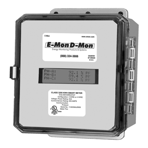
OPERATING MODES ® The E-Mon D-Mon Class 3200 meter is used to monitor electric power usage of individual loads after the utility meter and store kW and kVAR data for automatic meter reading. Fig. 21. Class 3200 Stand Alone Meter with 4 Line Display. -
Page 35: Normal Mode Display Screens
10.2 Normal Mode Display Screens The Class 3200 meter features seven Normal Mode Display Screens for monitoring the meter. Each screen is displayed for 5 second intervals, before scrolling onto the next screen. You can “lock” the scrolling display on any one of the seven screens. This will be explained in detail on following pages. -
Page 36: How To Program The Display Screens
DOWN MENU SELECT M33279 Fig. 24. Push Buttons. 10.3 How to Program the Display Screens The display information can be programed using four push buttons switches. The push buttons (DOWN, UP, SELECT, MENU) are located at the bottom of the display board on the inside front door of the meter. - Page 37 10.3.1 Date & Time To change the date and time, complete the following steps: 1. Press the MENU button. 2. The following screen will appear: Date & Time Device ID Reset KW/KWH Read Exit 3. Press the SELECT button. The date and time screen will appear, and the 2 digit month will be blinking.
- Page 38 10.3.2 Device I.D. To change Device I.D., complete the following steps: 1. Press the MENU button. 2. The following screen will appear: Date & Time Device ID Reset KW/KWH Read Exit 3. Use the UP and DOWN buttons to select the Device ID line. Press the SELECT button.
- Page 39 10.3.3 Peak Demand Reset To reset the recorded peak kW demand, complete the following steps: 1. Press the MENU button until “Reset kW/kWh Read” is indicated by the arrow on the display. Date & Time Device ID Reset KW/KWH Read Exit 2.
- Page 40 10.3.4 Display Hold Feature You can “lock” the scrolling display so that it will stay locked on any one of the seven screens. To stop the display from scrolling, complete the following steps: 1. Press the UP and DOWN buttons to choose which of the six screens you would like to display.
-
Page 41: High Voltage Metering
CT secondary is installed as a continuous “loop”, with a single conductor connected to both secondary terminals. To convert the 0~5 amp signal to a 0~ 2 volt signal, E-MON’s Current Sensors are installed on the CT secondary conductor. A set of 25 amp sensors is used in this application. - Page 42 M34227 Fig. 25. High Voltage CT’s. M34228 Fig. 26. Wiring Diagram For 3-wire High Voltage Circuits. 62-0390-02...
- Page 43 “loop”, with a single lead connected to both secondary terminals. E-MON meters accept a 0~2 volt signal from their Current Sensors. To convert the 0~5 amp signal, the Current Sensors are installed on the CT secondary lead. A set of 25 amp sensors is used in this application.
-
Page 44: Class 3200 Protocol Definitions
12.0 CLASS 3200 PROTOCOL DEFINITIONS ModBus Customer Point Map: CL3200 Address Registers Format Description Units 3200 Integer Energy delivered Wh Pulse 40001 Integer Energy received Wh Pulse 40001 Integer Reactive energy delivered VARh Pulse R/W 40005 Integer Reactive energy received... - Page 45 ModBus Customer Point Map: CL3200 Address Registers Format Description Units 3200 41033 Float Real power, phase C 41035 Float Reactive power, phase A kVAR 41037 Float Reactive power, phase B kVAR 41039 Float Reactive power, phase C kVAR 41041 Float Apparent power, phase A 41043 Float...
- Page 46 ModBus Customer Point Map: CL3200 Address Registers Format Description Units 3200 41075 Float Phase angle, phase C Degree Float External Input 1 Pulse 41083 Float External Input 2 Pulse 41085 Custom Interval Day Block 44001 1 per Integer Interval Data Pulse 44007 interval...
- Page 47 BACnet Object Descriptors: CL3200 Instance BACnet BACnet Object Description Units Property 3200 Analog Energy delivered Present Value R Input Analog Energy received Present Value R Input Analog Reactive energy delivered kVARh Present Value R Input Analog Reactive energy received kVARh Present Value R Input Analog...
- Page 48 BACnet Object Descriptors: CL3200 Instance BACnet BACnet Object Description Units Property 3200 Analog Reactive power phase C kVAR Present Value R Input Analog Apparent power phase A Present Value R Input Analog Apparent power phase B Present Value R Input Analog Apparent power phase C Present Value R...
- Page 49 BACnet Object Descriptors: CL3200 Instance BACnet BACnet Object Description Units Property 3200 Analog Reserve A No units Present Value R Input Analog Reserve B No units Present Value R Input Analog Reserve C No units Present Value R Input Analog External Input 1 Pulse Present Value...
- Page 50 Instance ID BACnet Object BACnet Property CL3200 BACnet Device ID Device Object identifier BACnet Device ID Device Object name BACnet Device ID Device Object type BACnet Device ID Device System status BACnet Device ID Device Vendor name BACnet Device ID Device Vendor Identifier BACnet Device ID...
- Page 51 13.0 LIMITED METER WARRANTY Subject to the exclusions listed below, E-Mon will either repair or replace (at its option) any product that it manufactures and which contains a defect in material or workmanship. The following exclusions apply: 1. This Limited Warranty is only effective for a period of (5) five years following the date of manufacture when installed in accordance with manufacturer’s instruc-...
- Page 52 99 Washington Street Melrose, MA 02176 ® U.S. Registered Trademark © 2012 E-Mon 800.517.8431 62-0390-02 JPG Rev. 11-12 TestEquipmentDepot.com Printed in United States...
Need help?
Do you have a question about the Class 3200 and is the answer not in the manual?
Questions and answers