
Related Manuals for E-Mon D-Mon Class 1000


Summary of Contents for E-Mon D-Mon Class 1000
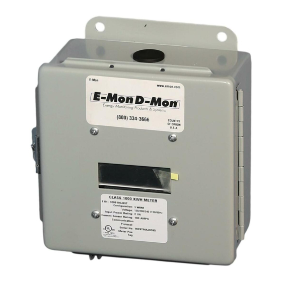
- Page 1 Test Equipment Depot - 800.517.8431 - 99 Washington Street Melrose, MA 02176 - TestEquipmentDepot.com Class 1000 Meter SINGLE PHASE kWh METER INSTALLATION INSTRUCTIONS 62-0388-01...
- Page 2 62-0388-01...
-
Page 3: Table Of Contents
CLASS 1000 METER TABLE OF CONTENTS Section 1.0 Pre-Installation Information Section 1.1 Internal Electronic Assemblies Section 1.2 Main Power Board Section 1.3 Display Board Section 2.0 Safety Label Definitions and Information Section 3.0 Precautionary and Safety Information Section 4.0 Meter Installation Section 4.1 Mounting the Meter Section 4.2... -
Page 4: Pre-Installation Information
CLASS 1000 METER 1.0 Pre-Installation Information The E-Mon D-Mon® Class 1000 kWh meter is a 2-element meter used to monitor electric power usage of individual loads after the utility meter. Installation must only be performed by qualified personnel and in accordance with these instructions and all applicable local and national electrical codes. -
Page 5: Internal Electronic Assemblies
CLASS 1000 METER 1.1. Internal Electronic Assemblies DISPLAY AND MAIN POWER KEYBOARD BOARD M33177 Fig. 1. Main Power Supply Board & Display Board The unit is comprised of a Main Power Board and Display and Keyboard. All component cards are mounted inside a UL Type 1 (standard) or NEMA 4X (optional) enclosure. -
Page 6: Main Power Board
CLASS 1000 METER 1.2 Main Power Board Connections to this board include the MAINS Input Voltage, Current Sensors, external IDR interface and Isolated Pulse Output. The MAINS input terminals are covered with a protective shield for safety purposes. The current sensor assemblies interface to three header connectors labeled A, B, and C along with conductor color indication. -
Page 7: Precautionary And Safety Information
CLASS 1000 METER 3.0 PRECAUTIONARY AND SAFETY INFORMATION CAUTION Internal circuit card components are extremely sensitive to electrostatic discharge. Be careful not to touch internal circuitry prior to discharging any static buildup on your person. To discharge yourself, touch a grounded metal object such as conduit or an earth-grounded metal enclosure. -
Page 8: Meter Installation
CLASS 1000 METER 4.0 METER INSTALLATION 4.1 Mounting the Meter STEP 1: Using the appropriate sized mounting hardware, fasten the Class 1000 meter enclosure to the selected mounting surface. The four mounting holes are centered 6.75” H x 4” W. The mounting hole spacing is identical for either the UL Type 1 or NEMA 4X enclosure. - Page 9 CLASS 1000 METER WARNING Failure to attach the protective earth ground wire securely to the enclosure creates a potential shock hazard. Do not operate the Class 1000 meter without a protective earth ground connection securely installed STEP 3: Wire Entry: Two openings exist on the unit enclosure, one for 1/2” conduit and one for 3/4”...
- Page 10 CLASS 1000 METER After all conductors are connected to their respective terminal block positions and tightened down, verify that each terminal block screw is securely fastened by gently tugging on each conductor. Verify that no conductor wires are frayed or are shorting to adjacent terminal block positions.
-
Page 11: Current Sensor Installation & Wiring
CLASS 1000 METER 4.3 Current Sensor Installation & Wiring Once the AC voltages have been confirmed to be within acceptable limits, you are ready to install the current sensors. The MAIN power board contains three header connectors located at the bottom right of the board. The connectors are labeled A, B, and C along with conductor color indication. -
Page 12: Installing The Split-Core Current Sensor Assembly
CLASS 1000 METER 4.4 Installing the Split-Core Current Sensor Assembly STEP 1: Each phase being monitored will require one two-piece current sensor assembly. Therefore, a three-phase meter will require three (3) assemblies. Open the two-piece current sensor assembly by releasing the nylon clamp using a flat head screwdriver. -
Page 13: Installing The Solid Core Current Sensor Assembly
CLASS 1000 METER 4.5 Installing the Solid-Core Current Sensor Assembly The optional solid-core current sensors can be installed in the same applications as the standard split-core units, however, the conductors that they are monitoring must first be disconnected. NOTE: Under no circumstances is this operation to take place without shutting off the power to the conductor(s) being monitored. -
Page 14: Current Sensor Wiring
CLASS 1000 METER 4.6 Current Sensor Wiring Once all the current sensors are installed on their appropriate phase conductors, you can begin terminating the current sensors on to the Class 1000 main power board. The current sensor leads can be extended up to 2,000 feet (using #14-22 AWG wire) for remote monitoring applications. - Page 15 CLASS 1000 METER SINGLE-PHASE, 3-WIRE CONNECTION 120/240-VOLT SINGLE-PHASE LINE VOLTAGE CURRENT SENSORS ∅A ∅B ∅A ∅B ∅C ∅A ∅B LOAD SOURCE NOTES: LINE VOLTAGE CONNECTION: #14 AWG SENSOR CONNECTION: B = BLACK W = WHITE IMPORTANT: LINE VOLTAGE MUST BE PRESENT AT THE A- AND B-PHASE VOLTAGE TERMINALS. SHORTING LINK MUST BE INSTALLED ON C-PHASE CURRENT SENSOR TERMINALS.
-
Page 16: Line Voltage/Current Sensor Diagnostic
CLASS 1000 METER 4.8 Line Voltage/Current Sensor Diagnostics M33181 Fig. 8. Main Board Configuration If the meter is not correctly wired, the “ERROR” indicator will be on. Verify that the AC MAINS voltage wires are all connected to the correct positions on the terminal block. -
Page 17: Final Main Board Checks
An open connection could exist at the plug terminals or at a splicing junction. Also verify a tight connection exists between the core halves. If error message is still appearing, contact E-Mon technical support at (800) 334-3666 for further assistance. -
Page 18: Monitoring Multiple Loads With One Meter
CLASS 1000 METER 5.0 MONITORING MULTIPLE LOADS WITH ONE METER The Class 1000 meter provides extreme flexibility by allowing additional sets of current sensors to be used in parallel so that multiple load locations can be monitored by one meter. This feature allows a totalized display readout from two or more load circuits. You may use parallel sensors to monitor specific breakers from one panel, specific breakers from more than one panel, two or more complete panels, etc. - Page 19 CLASS 1000 METER CURRENT SENSORS LINE VOLTAGE ØA ØB ØC ØAØB ØC W B W B W B ØA ØB LOAD SOURCE LOAD A ØA ØB LOAD SOURCE LOAD B M33204 Fig. 9. Multiple Load Locations Can Be Monitored By One Meter. 62-0388-01...
-
Page 20: Kwh Meter Features & Functions
CLASS 1000 METER 6.0 KWH METER FEATURES & FUNCTIONS 6.1 KWh Meter Display Functions Fig. 10. Normal Mode (kWh Reading) The Class 1000 kWh meter display requires no multiplier and shows kilowatt hours consumed. See section 6.2 for information on calculating cost based on kWh usage. Fig. -
Page 21: How To Read The Kwh Meter
Simply multiply the cost per kWh by the kWh reading from the E-Mon D-Mon meter. The resultant figure is the dollar cost for power used by the load(s) being monitored by this meter. -
Page 22: Kwh Meter Hardware Functions
CLASS 1000 METER 6.3 KWh Meter Hardware Functions IDR Jack 8-pin RJ-45-used to connect kWh meter to the E- Mon Energy automatic meter reading system. Calibration Jack Connector J11 is for factory calibration only, and is not a user accessible port. Silicon plug is not to be removed. - Page 23 CLASS 1000 METER SELECT MENU DOWN M33183 Fig. 15. Hardware Functions 62-0388-01...
-
Page 24: Preventative/Scheduled Maintenance
CLASS 1000 METER 7.0 PREVENTATIVE/SCHEDULED MAINTENANCE The Class 1000 kWh/single phase meter is shipped in calibrated, tested and fully functional condition. - No field adjustments are required. - No preventative or scheduled maintenance is required. - No cleaning or decontamination procedures are required for this instrument. 62-0388-01... -
Page 25: Troubleshooting Guide
Check sensor wiring to the terminal strip in meter (color coding B & W.) NOTE: If you still need assistance after performing the above troubleshooting proce- dures, do not remove the unit. Before removing the unit, contact E-Mon’s technical support department at (800) 334-3666, our support experts will... -
Page 26: Frequently Asked Questions
CLASS 1000 METER 9.0 FREQUENTLY ASKED QUESTIONS Q. When providing line voltage to the meter, can I tap off of the same breaker I am monitoring? A. Yes, the voltage can be pulled from the same breaker being monitored. Q. Can the meter’s line voltage wires be run in the same conduit as the sensor leads? A. - Page 27 Q. I’ve gone through the troubleshooting guides and I still can’t get my meter to work. What should I do? A. Before removing the unit, contact E-Mon’s technical support department at (800) 334-3666. Our technical support experts will assist you in detailed troubleshooting of the meter installation and assist you in getting the meter functional without having to remove and return the unit.
-
Page 28: Meter Technical Specifications
Ordering Information: Define brand, class, input voltage, current sensor amperage, enclosure type, and sensor type in the format A-B-CC-DDD-EEE-F-GGG where: A = Brand: E for E-Mon, H for Honeywell B = 10 for Class 1000 CCC = Numbers of conductors (including common/neutral): 2 or 3... - Page 29 CLASS 1000 METER Altitude 2000 Meters Maximum Voltage Overload +25% Continuously: +100% For 20 Cycles Current Sensor 100% For 1 Minute Without Damaging Meter Overload Pollution Degree Degree 2 In Accordance With IEC 664 Installation Category 3 (Overvoltage) Category Measurement Category 3 Category Enclosure Material...
- Page 30 62-0388-01...
- Page 31 CLASS 1000 METER 62-0388-01...
- Page 32 CLASS 1000 METER 99 Washington Street Melrose, MA 02176 800.517.8431 TestEquipmentDepot.com...
Need help?
Do you have a question about the D-Mon Class 1000 and is the answer not in the manual?
Questions and answers