
Related Manuals for E-Mon Class 2000


Summary of Contents for E-Mon Class 2000
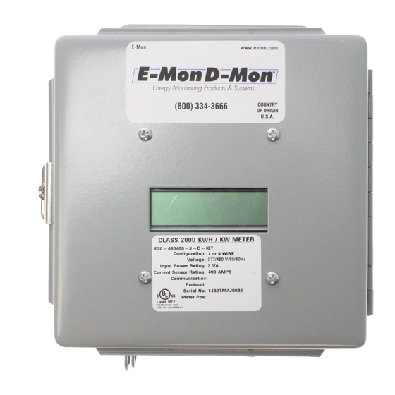
- Page 1 Class 2000 Meter KWH & KWH/DEMAND METER INSTALLATION INSTRUCTIONS E-Mon 850 Town Center Drive Langhome, PA 19047 (800)334-3666 www.emon.com 62-0389-03...
- Page 2 Before installing your new E-Mon product, please read the information on the following pages carefully. We believe that you will find the E-Mon D-Mon meters easy to install and to use for monitoring and evaluating your electrical usage.
-
Page 3: Table Of Contents
Section 6.2 How to Read the kWh Meter Section 6.3 KWh Meter Hardware Functions Section 6.4 Class 1000 and Class 2000 Pulse Output Removable Two-Screw Terminal Plug Section 7.0 KWh/Demand Meter Features & Functions* Section 7.1 KWh/Demand Meter Display Functions Section 7.2... -
Page 4: Pre-Installation Information
CLASS 2000 METER 1.0 PRE-INSTALLATION INFORMATION The E-Mon D-Mon® Class 2000 kWh/Demand meter is a 3-element meter used to monitor electric power usage of individual loads after the utility meter. Installation must only be performed by qualified personnel and in accordance with these instructions and all applicable local and national electrical codes. -
Page 5: Internal Electronic Assemblies
WARNING Use of this instrument, Class 2000, in a manner inconsistent with this manual or not specified by the manufacturer in writing, can cause permanent damage to the unit and/or serious injury to the operator. The protection and safety features provided by this equipment may become impaired or otherwise compromised. -
Page 6: Safety Label Definitions And Information
CLASS 2000 METER 1.1.1 Main Power Board Connections to this board include the MAINS Input Voltage, Current Sensors, external IDR interface and Isolated Pulse Output. The MAINS input terminals are covered with a protective shield for safety purposes. The current sensor assemblies interface to three header connectors, labeled A, B, and C along with conductor color indication. -
Page 7: Precautionary And Safety Information
WARNING Failure to ground the enclosure creates a possible shock hazard. Do not operate the Class 2000 meter without a protective earth wire attached securely to the PE terminal screw. After installing protective earth wiring, secure the screw tightly (7in-lb torque.) WARNING NEVER open front panel of unit while unit has MAINS power applied. -
Page 8: Meter Installation
ESD protection. Prior to performing any unit wiring, be sure to discharge any static on your person. 2. Install the Class 2000 Protective Earth Ground. Connect an earth ground wire to the Class 2000 protective earth ground terminal screw located on the right side of the line voltage terminal block. - Page 9 CLASS 2000 METER WARNING Failure to attach the protective earth ground wire securely to the enclosure creates a potential shock hazard. Do not operate the Class 2000 meter without a protective earth ground connection securely installed. 3. Wire Entry. a. Two openings exist on the unit enclosure, one for 1/2” conduit and one for 3/ 4”...
- Page 10 Activate the external circuit breaker or equivalent switch to apply AC MAINS power to the unit. 7. The Class 2000 meter display should turn on and indicate total kWh accumula- tion reading. NOTE: On demand meters the unit display, clock and other critical configuration parameters will be reset once the unit installation and wiring is complete.
-
Page 11: Current Sensor Installation & Wiring
C along with conductor color indication. This format must be followed in order for the meter to function correctly. The Class 2000 meter will be used with one of two basic types of current sensors: a. Split-Core Current Sensor: This sensor opens so that it can be attached around the circuit conductor being monitored without interrupting power. - Page 12 CLASS 2000 METER 4.3.1 Installing the Split-Core Current Sensor Assembly Each phase being monitored will require one two-piece current sensor assembly. Therefore, a three-phase meter will require three (3) assemblies. Open the two-piece current sensor assembly by releasing the nylon clamp using a flat head screwdriver.
- Page 13 Once all the current sensors are installed on their appropriate phase conductors, you can begin terminating the current sensors on to the Class 2000 main power board. The current sensor leads can be extended up to 2,000 feet (using #14-22 AWG wire) for remote monitoring applications.
-
Page 14: Mains Line Voltage & Current Sensor Wiring
CLASS 2000 METER 4.4 MAINS Line Voltage & Current Sensor Wiring Diagrams CURRENT SENSORS LINE VOLTAGE 3-PHASE, 4-WIRE INSTALLATION DIAGRAM NOTES: LINE VOLTAGE CONNECTIONS: #14-12 AWG SENSOR CONNECTIONS: B = BLACK LEAD W = WHITE LEAD NEUTRAL NOT USED IN DELTA SYSTEM. REMOVE NEUTRAL TERMINAL BLOCK SCREW FOR DELTA SYSTEMS. - Page 15 CLASS 2000 METER SINGLE-PHASE, 3-WIRE CONNECTION 120/208/240-VOLT SINGLE-PHASE NOTES: LINE VOLTAGE CURRENT SENSORS LINE VOLTAGE CONNECTION: #14 AWG SENSOR CONNECTION: B = BLACK W = WHITE IMPORTANT: LINE VOLTAGE MUST BE PRESENT AT THE A- AND B-PHASE VOLTAGE TERMINALS. SHORTING LINK MUST BE INSTALLED ON C-PHASE CURRENT SENSOR TERMINALS.
-
Page 16: Installation Overview
CLASS 2000 METER 4.5 Installation Overview METER TERMINAL BLOCK CONNECTIONS CURRENT SENSOR AND VOLTAGE CONNECTIONS M34224 Fig. 10. Install Overview. 4.6 Check Polarity of the Current Sensor. Verify all phases are loaded by at least 1% of meter rated load, and check the polarity of the sensors. - Page 17 CLASS 2000 METER Fig. 12. Error LED. Repeat the process for the C sensor gray plug. With only the C sensor plug connected, if the sensor error remains clear, then the C sensor input and the polarity is correct. Fig. 13. Error LED.
-
Page 18: Monitoring Multiple Loads With One Meter
Rule 2: All sensors used in parallel must be of the same amperage rating (i.e. 100 amp, 200 amp, etc.) The rating is determined by the current rating (amperage) of the Class 2000 meter. For example, a 200 amp meter must use extra sets of 200 amp current sensors. - Page 19 CLASS 2000 METER CURRENT SENSORS LINE VOLTAGE ØA ØB ØC ØAØB ØC N PE W B W B W B ØA ØB ØC LOAD SOURCE LOAD A ØA ØB ØC LOAD SOURCE LOAD B M33187 Fig. 14. Multiple Loads with one Meter.
-
Page 20: Kwh Meter Features & Functions
See section 6.2 for information on calculating cost based on kWh usage. Fig. 16. KW Load Mode (Current Load in kW). The Class 2000 kWh meter LOAD display shows the present circuit load in kilowatts. Fig. 17. Start Up Mode. -
Page 21: How To Read The Kwh Meter
Simply multiply the cost per kWh by the kWh reading from the E-Mon D-Mon meter. The resultant figure is the dollar cost for power used by the load(s) being monitored by this meter. -
Page 22: Kwh Meter Hardware Functions
CLASS 2000 METER 6.3 KWh Meter Hardware Functions IDR Jack 8-pin RJ-45-used to connect kWh meter to the E-Mon Energy automatic meter reading system. Calibration Jack Connector J11 is for factory calibration only, and is not a user accessible port. Silicon plug is not to be removed. - Page 23 CLASS 2000 METER CALIBRATION PULSE OUTPUT JACK IDR JACK DESCRIPTION ABOVE POWER ON LED METER PULSE LED ERROR MAIN POWER TERMINAL BLOCK HEADER CONNECTOR (CURRENT SENSORS) M33212 Fig. 19. Hardware Functions. MENU SELECT DOWN M33183 Fig. 20. Hardware Functions. 62-0389-03...
-
Page 24: Kwh/Demand Meter Features & Functions
(*Applies to meters equipped with the Demand Option) 7.1 KWh/Demand Meter Display Functions The Class 2000 kWh/Demand meter has a single display window that cycles through the energy data screens. The meter will cycle through four (4) separate screens. The screens are described below. -
Page 25: How To Read The Kwh/Demand Meter
Simply multiply the cost per kWh by the kWh reading from the E-Mon D-Mon meter. The resultant figure is the dollar cost for power used by the load(s) being monitored by this meter. -
Page 26: Demand Display Set-Up
CLASS 2000 METER 7.3 Demand Display Set-Up HOME ENTER DOWN M33207 The demand meter display is set-up using the four buttons located on the meter display board which is mounted on the door inside the meter enclosure. STEP 1: Press the HOME button to enter the menu screen. - Page 27 CLASS 2000 METER STEP 6: Press the DOWN button to access the TIME screen. STEP 7: Press ENTER to cycle between the hour, minutes, and day of week selection Use the UP and DOWN buttons to change the selection. STEP 8:When the changes are completed press the ENTER button to save the changes.
-
Page 28: Demand Reset
CLASS 2000 METER STEP 12: Press the HOME button to return to the setup screen. STEP 13: Press the UP arrow to display the MENU screen. STEP 14: Press the ENTER button to enter the normal display screen. 7.4 Demand RESET STEP 1: Press the HOME button to access the Series 2000 MENU screen.\... -
Page 29: Preventative/Scheduled Maintenance
STEP 6: Press ENTER to return to the normal display. 8.0 PREVENTATIVE/SCHEDULED MAINTENANCE The Class 2000 kWh/Demand meter is shipped in a calibrated, tested and fully functional condition. - No field adjustments are required. - No preventative or scheduled maintenance is required. -
Page 30: Lithium Battery Replacement Instructions
9.0 LITHIUM BATTERY REPLACEMENT INSTRUCTIONS The Class 2000 kWh/Demand meter has a Lithium Battery Cell, which is used to retain the contents of SRAM and the RTC during power outages. The battery has a life expectancy of greater than 5 years. - Page 31 CLASS 2000 METER WARNING WARNING: Only replace battery with Panasonic part number CR2032 only. Use of another battery may present a risk or explosion. See owners manual for safety instructions. Internal circuit card components are extremely sensitive to electrostatic discharge. Be careful not to touch internal circuitry prior to discharging any static buildup on your person.
-
Page 32: Troubleshooting Guide
CLASS 2000 METER 10.0 TROUBLESHOOTING GUIDE The Class 2000 kWh/Demand meter is calibrated and tested at the factory before being packaged and shipped. If installed properly and in accordance with these installation instructions, your Class 2000 meter should provide years of trouble free service. -
Page 33: Line Voltage Diagnostics
CLASS 2000 METER 10.1 Line Voltage Diagnostics E-Mon meters detect the direction of rotation of three-phase power. The proper phase sequence must be A-B-C. The AC power input must be in proper phase sequence A, B, C. If incorrect, the display will read “Check Install.”... -
Page 34: Current Sensor Diagnostics
“Load” is the power going out (“downstream”) of the device that interrupts power. Fig. 28. Load Side. .Still have questions? Call the E-Mon Technical Support Hotline: M-F 8AM to 7:30 PM Eastern Time Zone: 800-334.3666 or M-F 8AM to 4:30 PM Western Time Zone: 800-810-3666. -
Page 35: High Voltage Metering
CT secondary is installed as a continuous “loop”, with a single conductor connected to both secondary terminals. To convert the 0~5 amp signal to a 0~ 2 volt signal, E-MON’s Current Sensors are installed on the CT secondary conductor. A set of 25 amp sensors is used in this application. - Page 36 CLASS 2000 METER M34227 Fig. 29. High Voltage CTs. M34228 Fig. 30. Wiring Diagram For 3-wire High Voltage Circuits. 62-0389-03...
- Page 37 “loop”, with a single lead connected to both secondary terminals. E-MON meters accept a 0~2 volt signal from their Current Sensors. To convert the 0~5 amp signal, the Current Sensors are installed on the CT secondary lead. A set of 25 amp sensors is used in this application.
-
Page 38: Frequently Asked Questions
CLASS 2000 METER 12.0 FREQUENTLY ASKED QUESTIONS Q. When providing line voltage to the meter, can I tap off of the same breaker I am monitoring? A. Yes, the voltage can be pulled from the same breaker being monitored. Q. Can the meter’s line voltage wires be run in the same conduit as the sensor leads? A. - Page 39 Q. I’ve gone through the troubleshooting guides and I still can’t get my meter to work. What should I do? A. Before removing the unit, contact E-Mon’s technical support department at (800) 334-3666. Our technical support experts will assist you in detailed troubleshooting of the meter installation and assist you in getting the meter functional without having to remove and return the unit.
-
Page 40: Meter Technical Specifications
Ordering Information: Define brand, class, input voltage, current sensor amperage, enclosure type, and sensor type in the format A-BB-CCC-DDDD-E-F-GGG where: A = Brand: E for E-Mon BB = Class: 20 for Class 2000 CCC = Input Voltage: 120, 208, 480 or 600 DDDD = Amperage: 100, 200,400,800,1600, or 3200 E = Enclosure Type: J = standard metal, R= 4X raintite, M = MMU F = Demand Option: D for Demand “blank”... - Page 41 CLASS 2000 METER Input Voltage 3-wire (Delta) Or 4-wire (Wye) Configuration Mains Voltage Input Up To 480 VAC RMS Available Input Power 6 VA Maximum Rating Current Sensor Up To 3200 Amps RMS AC Available Rating Power Factor 0.5 Leading Or Lagging...
- Page 42 CLASS 2000 METER Modem Interface Cable: UL-listed Telephone Cord, 6-cond. 300 VAC, Stranded Cond. 22-26 AWG. Cable Connector: RJ-45 male IDC Input/Output Voltage: +5 VDC/18 VAC Ckt Input Isolation 5.3K VAC for 1 Minute Baud Rate: 9600 IDR Interface Port...
-
Page 43: Meter Limited Warranty
CLASS 2000 METER 14.0 METER LIMITED WARRANTY Subject to the exclusions listed below, E-Mon will either repair or replace (at its option) any product that it manufactures and which contains a defect in material or workmanship. The following exclusions apply: 1. - Page 44 CLASS 2000 METER E-Mon 850 Town Center Drive Langhorne, PA 19047 ® U.S. Registered Trademark www.emon.com © 2012 E-Mon 62-0389-03 JPG Rev. 11-12 info@emon.com Printed in United States...
Need help?
Do you have a question about the Class 2000 and is the answer not in the manual?
Questions and answers