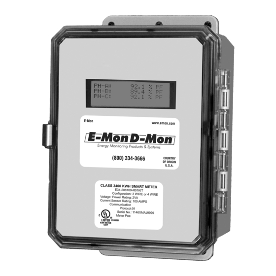
Summary of Contents for E-Mon Class 3400 Meter
- Page 1 Class 3400 Meter ADVANCED KWH/DEMAND METER WITH COMMUNICATIONS INSTALLATION INSTRUCTIONS E-Mon 1985 Douglas Drive North Golden Valley, MN 55422 www.emon.com info@emon.com 62-0391-03...
- Page 2 Before installing your new E-Mon product, please read the information on the following pages carefully. We believe that you will find the E-Mon D-Mon meters easy to install and to use for monitoring and evaluating your electrical usage.
- Page 3 Section 4.0 Safety Label Definitions and Information Section 5.0 Precautionary/Safety Information Section 6.0 Meter Installation Section 6.1 Mounting the Class 3400 Meter Section 6.2 Main Power Board Connections Section 6.3 Phasing of Line Voltage Section 6.4 Current Sensor Installation & Wiring Section 6.5...
- Page 4 600V 600V, 3 Phase Verify that the Class 3400 meter’s current sensors are sized suitably for the load to be monitored. Compare the color of the arrows on the current sensors to the chart below to confirm the correct current sensor is being used.
- Page 5 WARNING Use of this instrument, the E-Mon D-Mon Class 3400, in a manner inconsistent with this manual or not specified by the manufacturer in writing, can cause permanent damage to the unit and/or serious injury to the operator.
- Page 6 CLASS 3400 METER 2.1 Main Power Board Connections to this board include the MAIN Power Input and current sensors.The MAIN Power Input terminals are positions one through four on the four position screw terminal block, TB1. These terminals are covered with a protective shield for safety purposes.
- Page 7 CLASS 3400 METER 2.2 Display Board The display board connects to the main power board via a flex ribbon cable and the board mounts on the inside of the housing door.No additional connections to the display board are required. The display board’s LCD readout indicates the metered values as well as errors associated with the Class 3400 meters, such as phase loss or sensor error conditions.
- Page 8 A-BB-CCC-DDDD-E-FF-G-HHH, where: A = Brand: E for E-Mon BB = designates Class: 3200 (32), 3400 (34), or 5000 (50) meter CCC = input voltage: (208, 480, 600, 120 volt for high voltage applications only)
- Page 9 CLASS 3400 METER 3.0 METER TECHNICAL SPECIFICATIONS (CONTINUED) Input Voltage 3-wire (Delta) Or 4-wire (Wye) Configuration Mains Voltage Input Up To 600 VAC RMS Available Input Power 6 VA Maximum Rating Current Sensor Up To 3200 Amps RMS AC Available...
- Page 10 CLASS 3400 METER 3.0 METER TECHNICAL SPECIFICATIONS (CONTINUED) RS-485 Serial Cable: UL-listed stranded conductors, Communications 22-26 AWG. Input/Output Voltage: Ground-isolated +/-5.4VDC Cable Connector: Screw terminal termination Circuit Input Isolation: 5.3kVAC Max Cable Distance: 4000 feet Max Network Nodes: 64 cabling nodes (including...
- Page 11 CLASS 3400 METER 4.0 SAFETY LABEL DEFINITIONS AND INFORMATION The Class 3400 meter may contain one or more of the following labels. Operator(s) should familiarize themselves with the meaning of each label to minimize risk. Notice This equipment has been tested and found to comply with the limits for a Class B digital device, pursuant to part 15 of the FCC Rules.
- Page 12 WARNING Failure to ground the enclosure creates a possible shock hazard. Do not operate the Class 3400 meter without a protective earth wire attached securely to the PE terminal screw. After installing protective earth wiring, secure the screw tightly (7 N-m torque.) WARNING NEVER open front panel of unit while unit has MAINS power applied.
- Page 13 CLASS 3400 METER 6.0 METER INSTALLATION 6.1 Mounting the Class 3400 Meter 6-35/64 (166) 5/8 (16) 6-35/64 (166) 7-51/64 (198) Ø 1-3/32 (28) THROUGH 3-17/64 (83) NEAR SIDE ONLY 3-25/64 (86) 1-5/8 (41) M34684 Use appropriately sized mounting hardware to fasten the meter enclosure to the selected mounting surface.
- Page 14 External Switch Mechanism/In-Line Fuse Installation To ensure a safe installation, the Class 3400 meter requires an external switch mechanism, such as a circuit breaker, be installed on the meter’s MAINS input wiring. The switch mechanism must be installed in close prox-...
- Page 15 CLASS 3400 METER imity to the meter and easily reachable for the operator. This device must also be marked as the disconnecting device for the Class 3400 meter. Install 1/10 Amp Slow Activation in-line fuses with the suitable voltage rating for each conductor phase at the MAINS input to the meter.
- Page 16 CLASS 3400 METER 6.2 Main Power Board Connections (continued) Verify the voltage readings on Screen 5 using an AC voltmeter. Typical read- ings shown below are measured phase to neutral for 4 wire and phase to phase for 3 wire. Readings should be +/- 10% of nominal.
- Page 17 CLASS 3400 METER NOTE: The meter will be reset later via the software during “startup” proce- dures. 62-0391-03...
- Page 18 9&10. Factory installed jumper should not be removed. The Class 3400 meter can be used with two types of 0-2V current sensors. 1. Split-core current sensor. This sensor opens so that it can be attached around the circuit being monitored without interrupting power.
- Page 19 To do this, there must be at least 1% of the meter’s current rating (amps) flowing in each of the conductors being monitored. The Class 3400 meter’s diagnostic program will provide data to ensure that the current sensor installation is done properly.
- Page 20 CLASS 3400 METER 6.5 Main Power & Current Sensor Wiring Diagram LINE VOLTAGE CURRENT SENSORS 3-PHASE INSTALLATION DIAGRAM NOTES: LINE VOLTAGE CONNECTIONS: #14-22 AWG SENSOR CONNECTIONS: W = WHITE LEAD B = BLACK LEAD NEUTRAL NOT USED IN DELTA SYSTEM.


Need help?
Do you have a question about the Class 3400 Meter and is the answer not in the manual?
Questions and answers