
Related Manuals for Unigas HRX515


Summary of Contents for Unigas HRX515
- Page 1 HRX515 Gas / light oil dual fuel burners Progressive - Fully modulating MANUAL OF INSTALLATION - USE - MAINTENANCE BURNERS - BRUCIATORI - BRULERS - BRENNER - QUEMADORES - ГОРЕЛКИ M039334CA Rel. 0 10/2014...
-
Page 2: General Introduction
DANGERS, WARNINGS AND NOTES OF CAUTION THIS MANUAL IS SUPPLIED AS AN INTEGRAL AND ESSENTIAL PART OF THE PRODUCT AND MUST BE DELIVERED TO THE USER. INFORMATION INCLUDED IN THIS SECTION ARE DEDICATED BOTH TO THE USER AND TO PERSONNEL FOLLOWING PRO- DUCT INSTALLATION AND MAINTENANCE. -
Page 3: Directives And Standards
DIRECTIVES AND STANDARDS do not leave the equipment exposed to weather (rain, sun, etc.) unless expressly required to do so; Gas burners European directives: do not allow children or inexperienced persons to use equipment; - Directive 2009/142/EC - Gas Appliances; The unit input cable shall not be replaced by the user. -
Page 4: Symbols Used
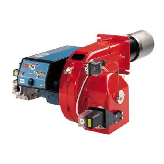
-EN 55014-1Electromagnetic compatibility - Requirements for household appliances, electric tools and similar apparatus. -UNI EN 676 (Gas Burners; -CEI EN 60335-1(Household and similar electrical appliances - Safety. Part 1: General requirements; - EN 50165 Electrical equipment of non-electric appliances for household and similar purposes. - Page 5 PART I: SPECIFICATIONS PART I: SPECIFICATIONS 1.0 BURNERS FEATURES Note: the figure is indicative only Keys 1 Mimic panel with startup switch 2 Gas filter 4 Gas valve group 5 Cover 6 Flange 7 Blast tube-Combustion head group 8 Oil pressure governor 9 Actuator 10 Adjusting cams 11 Air intake...
-
Page 6: Burner Model Identification
PART I: SPECIFICATIONS 1.1 Burner model identification Burners are identified by burner type and model. Burner model identification is described as follows. Type HRX515 Model MD. S. BURNER TYPE HRX515 FUEL M - Natural gas OPERATION (Available versions) PR - Progressive... -
Page 7: Burner Type
PART I: SPECIFICATIONS 1.2 Technical Specifications BURNER TYPE HRX515 770 - 4400 Output min. - max. kW Natural gas - Light oil Fuel see next paragraph Category 81 - 466 min.- max. (Stm Gas rate- Natural gas see Note 2... - Page 8 1.4 Overall dimensions (mm) Burner flange Boiler recommended drilling tem- AA AB AC AD AE AN AP 50 1731 323 910 475 35 415 594 100 530 508 1201 446 1721 1079 642 305 345 494 540 582 M14 552 390 390 755 150 605 843 216 852 328 270 65 1731 323 910 475 35 415 612 118 530 508 1201 446 1691 1049 642 305 345 494 540 582 M14 552 390 390 633 150 483 843 292 852 328 270 HRX515A 80 1731 323 910 475 35 415 626 132 530 508 1201 446 1725 1084 642 305 345 494 540 582 M14 552 390 390 685 150 535 875 322 852 328 270...
- Page 9 HXR515A Fig. 4 - 3I2MG-24 v0 Hydraulic diagram ON BOARD ITEMS SUPPLIED LOOSE ITEMS oil inlet oil outlet 19.1 gas inlet combustion air BY OTHERS BY BURNER CONSTRUCTOR...
- Page 10 3I2MG24 LEGEND rev.0 OIL TRAIN MAIN GAS TRAIN Filter Manual valve Flexible hose Bellows unit Pump and pressure governor Filter Electrical motor Pressure switch - PGMIN Flexible hose Safety valve with built in gas governor Solenoid valve Proving system pressure switch - PGCP Flexible hose Pressure switch - PGMAX...
-
Page 11: Performance Curves
Power kW Potenza / Output (kW) 1.7 Performance Curves HRX515 To get the input in kcal/h, multiply value in kW by 860. Data are referred to standard conditions: atmospheric pressure at 1013mbar, ambient temperature at 15°C NOTE: The performance curve is a diagram that represents the burner performance in the type approval phase or in the laboratory tests, but does not represent the regulation range of the machine. - Page 12 PART I: SPECIFICATIONS 1.8 Pressure in the Network / gas flow rate curves(natural gas) HRX515 Caution: the gas rate value is quoted on the x-axis, the related network pressure is quoted on the y-axis (pressure value in the combustion chamber is not included). To know the minimum pressure at the gas train inlet, necessary to get the requested gas rate, add the pressure value in the combustion chamber to the value read on the y-axis.
- Page 13 ATTENTION: THE BURNED GAS RATE MUST BE READ AT THE GAS FLOW METER. WHEN IT IS NOT POSSIBLE, THE USER CAN REFERS TO THE PRESSURE-RATE CURVES AS GENERAL INFORMATION ONLY. 1.11 Pressure - rate in combustion head curves (natural gas) Curves are referred to pressure = 0mbar in the combustion chamber! HRX515...
- Page 14 PART II: INSTALLATION PART II: INSTALLATION 2.0 MOUNTING AND CONNECTING THE BURNER 2.1 Packing The burners are despatched in wooden crates whose dimensions are: 5xxA series: 1886mm x 1456mm x 1120mm (L x P x H) Packing cases of this type are affected by humidity and are not suitable for stacking. The following are placed in each packing case: burner with detached gas train;...
- Page 15 PART II: INSTALLATION 2.3 Fitting the burner to the boiler To install the burner into the boiler, proceed as follows: make a hole on the closing door of the combustion chamber as described on paragraph “Overall dimensions”) place the burner to the boiler: lift it up and handle it according to the procedure described on paragraph “Handling the burner”; place the 4 stud bolts (5) on boiler’s door, according to the burner drilling template described on paragraph “Overall dimensions”;...
- Page 16 PART II: INSTALLATION spacer to move the burner backwards or to design a blast tube tha suites the utilisation (please, contact the manifacturer). a) Heat output in kW b) Lenght of the flame tube in meters c) Flame tube firing intensity in MW/m d) Combustion chamber diameter (m) Fig.
-
Page 17: Gas Inlet
PART II: INSTALLATION 3.0 GAS TRAIN CONNECTIONS The diagrams show the components of the gas trai included in the delivery and which must be fitted by the installer.The diagrams are in compliance with the current laws. ATTENTION: BEFORE EXECUTING THE CONNECTIONS TO THE GAS PIPE NETWORK, BE SURE THAT THE MANUAL CUTOFF VALVES ARE CLOSED. - Page 18 PART II: INSTALLATION 3.1 Assembling the gas grain gas supply network ”direction” arrows for installation Keys 1A..1E Gasket Gas filter Gas valves group Bellows unit Manual valve Fig. 7 - Example of gas train To mount the gas train, proceed as follows: 1-a) in case of threaded joints: use proper seals according to the gas used;...
- Page 19 PART II: INSTALLATION WARNING: removing the four screws BS causes the device to be unserviceable! SKP1. SKP2. 7631z05/0101 SIEMENS VGD..MOUNTING POSITIONS Fig. 9 Fig. 10 Fig. 8 (spring) (cap) Fig. 11 Siemens VGD valves with SKP actuator : The pressure adjusting range, upstream the gas valves group, changes according to the spring provided with the valve group. 0 - 22 15 - 120 100 - 250...
- Page 20 PART II: INSTALLATION If all of the test phases are passed the proving system test is successful, if not a burner lockout happens. On LMV5x and LMV2x/3x and LME73 (except LME73.831BC), the valve proving can be parameterized to take place on startup, shut- down, or both.
- Page 21 PART II: INSTALLATION 3.5 OIL TRAIN CONNECTIONS 3.6 Hydraulic diagrams for light oil supplying circuits Fig. 12 - Gravity circuit Fig. 13 - Ring circuit Fig. 14 - Suction circuit Manual valve Light oil filter Light oil feeding pump One way valve Flexible hoses Relief valve...
- Page 22 PART II: INSTALLATION 3.7 Installation diagram of light oil pipes PLEASE READ CAREFULLY THE “WARNINGS” CHAPTER AT THE BEGINNING OF THIS MANUAL. From tank To tank Fig. 15 - Double-pipe system The burner is supplied with filter and flexible hoses, all the parts upstream the filter and downstream the return flexible hose, must be installed by the customer.
- Page 23 PART II: INSTALLATION 3.8 About the use of fuel pumps Do not use fuel with additives to avoid the possible formation over time of compounds which may deposit between the gear teeth, thus obstructing them. After filling the tank, wait before starting the burner. This will give any suspended impurities time to deposit on the bottom of the tank, thus avoiding the possibility that they might be sucked into the pump.
- Page 24 PART II: INSTALLATION Suntec TA.. Oil viscosity 3 ÷ 75 cSt Oil temperature 0 ÷ 150°C Min. suction pressure - 0.45 bar to avoid gasing Max. suction pressure 5 bar Max. return pressure 5 bar Rotation speed 3600 rpm max. 1.
-
Page 25: Electrical Connections
PART II: INSTALLATION 4.0 ELECTRICAL CONNECTIONS WARNING! Respect the basic safety rules. make sure of the connection to the earthing system. do not reverse the phase and neutral connections. fit a differential thermal magnet switch adequate for connection to the mains. - Page 26 PART III: OPERATION PART III: OPERATION WARNING: before starting the burner up, be sure that the manual cutoff valves are open and check that the pres- sure upstream the gas train complies the value quoted on paragraph “Technical specifications”. Be sure that the mains switch is closed.
-
Page 27: Gas Operation
PART III: OPERATION Keys Main switch (0=Off, 1=GAS, 2=OIL) Reset pushbutton for control box CMF switch (0=stop, 1=low flame, 2=high flame, 3=automatic) - fully modulating burners only Gas proving system reset pushbutton (only for burners with Siemens LDU11 provided) Lock-out LED Hi-flame operation LED Lo-flame operation LED “Ignition transformer operation”... -
Page 28: Light Oil Operation
PART III: OPERATION 4.4 Light oil operation The fan motor starts and the pre-purge phase as well. Since the pre-purge phase must be carried out at the maximum air rate, the control box drives the actuator opening and when the maximum opening position is reached, the pre-purge time counting starts. At the end of the pre-purge time, the actuator is in the light oil ignition position: the ignition transformer is energised (lamp B4 on);... - Page 29 PART III: OPERATION AIR FLOW AND FUEL ADJUSTMENT WARNING! During commissioning operations, do not let the burner operate with insufficient air flow (danger of formation of carbon monoxide); if this should happen, make the fuel decrease slowly until the normal combustion values are achieved.
-
Page 30: Adjustments For Gas Operation
PART III: OPERATION ADJUSTMENTS FOR GAS OPERATION 6.1 Adjustments - brief description Adjust the air and gas flow rates at the maximum output (“high flame”) first, by means of the air damper and the valves group pressure stabiliser respectively. Check that the combustion parameters are in the suggested limits. Check the flow rate measuring it on the counter or, if it was not possible, verifying the combustion head pressure by means of a differential pressure gauge, as described on par. - Page 31 PART III: OPERATION Siemens VGD.. To adjust the air flow rate in the high flame stage, loose the RA nut and screw VRA as to get the desired air flow rate: moving the rod TR towards the air damper shaft, the air damper opens and consequently the air flow rate increases, moving it far from the shaft the air damper closes and the air flow rate decreases.
- Page 32 PART III: OPERATION 6.3 Fully-modulating burners .To adjust the fully-modulating burners, use the CMF switch on the burner control panel (see next picture), instead of the TAB thermo- stat as described on the previous paragraphs about the progressive burners. Go on adjusting the burner as described before, paying attention to use the CMF switch intead of TAB.
- Page 33 PART III: OPERATION remove the pressure switch plastic cover; if the maximum pressure switch is mounted upstreaam the gas valves: measure the gas pressure in the network, when flame is off; by means of the adjusting ring nut VR, set the value read, increased by the 30%. if the maximum pressure switch is mounted downstream the “gas governor-gas valves”...
- Page 34 PART III: OPERATION 6.11 Center head holes gas flow regulation To adjust the gas flow, partially close the holes, as follows: loosen the three V screws that fix the adjusting plate D; insert a screwdriver on the adjusting plate notches and let it move CW/CCW as to open/close the holes; once the adjustmet is performed, fasten the V screws.
- Page 35 Fig. 17 (as far as reading the pressure values, see next paragraphs). NOZZLE HIGH FLAME LOW FLAME NOZZLE SUPPLY PRESSURE RETURN PRESSURE RETURN PRESSURE FLUIDICS WR2/UNIGAS M3 19-20 7 (recommended BERGONZO A3 11 ÷ 13 6 (recommended) MONARCH NOZZLE Pressure nozzle...
- Page 36 PART III: OPERATION Fig. 17 Example (Bergonzo): if a 220kg/h flow rate BERGONZO nozzle is provided, set the return pressure at 11bar, supply at 20bar on the delivery to get a 220kg/h flow rate. If the return pressure needed is 5bar, instead, act on the V adjusting screw on the pressure gover- nor.
- Page 37 PART III: OPERATION Fig. 18...
- Page 38 PART III: OPERATION Oil Flow Rate Settings Once the air and gas flow rates are adjusted, turn the burner off, switch to the oil operation (OIL, on the burner control panel). with the electrical panel open, prime the oil pump acting directly on the related CP contactor (see next picture): check the pump motor rotation and keep pressing for some seconds until the oil circuit is charged;...
- Page 39 PART III: OPERATION tion. Turn the burner off; then start it up again. If the adjustment is not correct, repeat the previous steps. 8.2 Fully-modulating burners .To adjust the fully-modulating burners, use the CMF switch on the burner control panel (see next picture), instead of the TAB thermo- stat as described on the previous paragraphs about the progressive burners.
-
Page 40: Routine Maintenance
PART IV: MAINTENANCE PART IV: MAINTENANCE WARNING: ALL OPERATIONS ON THE BURNER MUST BE CARRIED OUT WITH THE MAINS DISCONNECTED AND THE FUEL MANAUL CUTOFF VALVES CLOSED! ATTENTION: READ CAREFULLY THE “WARNINGS” CHAPTER AT THE BEGINNIG OF THIS MANUAL.. At least once a year carry out the maintenance operations listed below. In the case of seasonal servicing, it is recommended to carry out the maintenance at the end of each heating season;... - Page 41 PART IV: MAINTENANCE 9.2 Replacing the spring in the gas valve group To replace the spring in the gas valve group,proceed as follows: Carefully twist the protection cap 1 and the O-ring 2. remove the “set value” spring 3 from housing 4. Replace spring 3.
- Page 42 PART IV: MAINTENANCE 9.5 Adjusting the combustion head Burner is factory-set according to its combustion head model. Attention! If it is necessary to change the head position, repeat the air and gas adjustments described at staps 1-9 in paragraph related to air/fuel ratio adjustments according to the actuator model. Attention :before adjusting the combustion head, turn the burner off and wait until it gets cold.
- Page 43 PART IV: MAINTENANCE Nozzles are factory set in order that: The smallest holes (pilot holes) are directed towards the flame axis while the biggest ones (main holes) are directed outwards. As for a finest adjustment in the plant, please contact the Technical service. The nozzles can be adjusted as follows: - back and forth adjustment, by means of V1 screws - up and down adjustment, by means of V2 screws...
- Page 44 PART IV: MAINTENANCE 9.6 Removing the combustion head Attention: before adjusting the combustion head, turn the burner off and wait until it gets cold. Remove the cover C. remove the electrodes cables; unscrew the 3 screws V which hold in position the gas manifold G and pull out the complete group as shown in the picture below. Clean the combustion head by a compressed air blow or, in case of scale, scrape it off by a scratchbrush.
-
Page 45: Seasonal Stop
PART IV: MAINTENANCE 9.7 Checking the detection current .To check the detection signal follow the scheme in the picture below. If the signal is less than the value indicated, check the position of the detection electrode or detector, the electrical contacts and, if necessary, replace the electrode or the detector. Control box Minimum detection signal 70µA with UV detector) -
Page 46: Troubleshooting
9.11 TROUBLESHOOTING TROUBLE CAUSE MAIN SWITCH OPEN LACK OF GAS MAXIMUM GAS PRESSURE SWITCH DEFECTIVE (IF PROVIDED) THERMOSTATS/PRESSURE SWITCHES DEFECTIVE FAN MOTOR THERMAL CUTOUT INTERVENTION OVERLOAD TRIPPED INTERVENTION AUXILIARY FUSES INTERRUPTED CONTROL BOX FAULTY DEFECTIVE ACTUATOR AIR PRESSURE SWITCH FAULT OR BAD SETTING MINIMUM GAS PRESSURE SWITCH DEFECTIVE OR GAS FILTER DIRTY IGNITION TRANSFORMER FAULT... - Page 47 11.0 BURNER EXPLODED VIEW NOTE: combustion head is indicative only.
- Page 48 ITEM DESCRIPTION ITEM DESCRIPTION BURNER HOUSING LEVERAGE 1.1.1 COVER 7.1.1 GAS VALVE HOUSING INSPECTION GLASS 7.1.2 SKP ACTUATOR INLET 7.1.3 SKP ACTUATOR CERAMIC FIBRE ROPE 7.1.4 GAS PROVING SYSTEM AIR PRESSURE SWITCH 7.1.6 GAS PRESSURE 1.5.1 AIR PRESSURE SWITCH GAS FILTER GASKET 1.7.1 AIR INTAKE DAMPER...
- Page 49 APPENDIX SIEMENS LFL 1.3.. CONTROL BOX consent to start-up by means of the thermostat or pressostat "R" start-up program Automatic programme in the event of interruption and indication of posi- tion when interrupted normal burner operation By default, in the event of any kind of interruption, the flow of fuel is imme- regulation stop caused by "R"...
- Page 50 Ionisation monitor Twin-tube burners (**) voltage in detector electrode Preignition time until the all clear to the pilot burner valve at normal working 330V ±10% terminal 17. test 380V ±10% First safety time (pilot flame strenght); at the end of the safety time short circuit current max.
- Page 51 Programmer diagram pre-ventilation time limit contact switch for damper OPEN position safety time block remote signal '1st safety time main relay (working network) with contacts "ar" pre-ignition time Monitor fuse 'pre-ignition time block relay with "br" contacts interval for creating current between terminals 18 and 19 fuel valve 'interval for creating current between terminals 17 and 19 reset button...
- Page 56 C.I.B. UNIGAS S.p.A. Via L.Galvani, 9 - 35011 Campodarsego (PD) - ITALY Tel. +39 049 9200944 - Fax +39 049 9200945/9201269 web site: www.cibunigas.it - e-mail: cibunigas@cibunigas.it Note: specifications and data subject to change. Errors and omissions exceptd.
Need help?
Do you have a question about the HRX515 and is the answer not in the manual?
Questions and answers