Table of Contents
Advertisement
Installation Instructions
Original Instructions
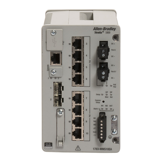
Stratix 5800 Ethernet Managed Switches
Catalog Numbers 1783-MMS10 Series A, 1783-MMS10E Series A, 1783-MMS10B Series A, 1783-MMS10BE Series A,
1783-MMS10R Series A, 1783-MMS10ER Series A, 1783-MMS10 Series B, 1783-MMS10E Series B, 1783-MMS10B Series B,
1783-MMS10BE Series B, 1783-MMS10R Series B, 1783-MMS10ER Series B, 1783-MMS10EA Series B, 1783-MMS10EAR Series B,
1783-MMX8T Series A, 1783-MMX8E Series A, 1783-MMX8EA Series A, 1783-MMX8S Series A, 1783-MMX8SA Series A,
1783-MMX6T2S Series A, 1783-MMX16T Series A, 1783-MMX16E Series A, 1783-MMX14T2S Series A
Topic
Page
5
6
6
7
8
8
9
10
11
12
12
13
14
14
14
14
15
16
Advertisement
Table of Contents


Need help?
Do you have a question about the Stratix 5800 and is the answer not in the manual?
Questions and answers