Table of Contents
Advertisement
Quick Links
Advertisement
Table of Contents

Subscribe to Our Youtube Channel
Related Manuals for CombiSteel Royal 42


Summary of Contents for CombiSteel Royal 42
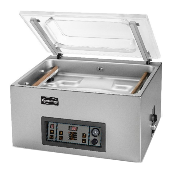
- Page 1 Vacuum Machine 7004.0035 Royal 42 7004.0040 Royal 52 User manual...
-
Page 2: Table Of Contents
CONTENT Preamble ................................ 5 Safety ................................5 List of the symbols used in this manual ....................5 Pictograms on the machine ........................5 General warnings ..........................6 Warnings during use ..........................6 Warnings for operating personnel ......................7 Introduction ..............................8 Description of the machine .......................... - Page 3 6.7.2.9 Sequential Vacuum (optional) ....................30 6.7.2.10 Marinating (optional) ....................... 31 6.7.2.11 Tenderising (optional) ......................31 6.7.2.12 Seal ............................31 6.7.2.13 Soft-air ............................32 6.7.2.14 External vacuum (optional) ...................... 32 6.7.2.15 Dealer Information ........................33 Guideline for function values ......................33 Printer (ACS only) ..........................
- Page 4 The machine is not suitable for the packaging of toxic, corrosive, irritant or potentially explosive materials. All persons responsible for the operation of this machine must at least fully read and understand the chapters about the operation and safety provided in these operating instructions.
-
Page 5: Preamble
Preamble This is the manual for your Combisteel vacuum packaging machine. This manual is intended for anyone who works with or services the machine. This manual contains information and instructions for installation, operation and maintenance of the machine. We recommend that you carefully read this manual before use and follow the procedures and instructions strictly. -
Page 6: General Warnings
Regularly check whether the pictograms and markings are still clearly recognizable and legible. Replace them if this is not the case. General warnings • All persons responsible for the operation of this machine must at least fully read and understand the chapters Safety on page 5 and Operation on page 17. •... -
Page 7: Warnings For Operating Personnel
Warnings for operating personnel • Operating personnel must be 18 years or older. • Only authorised persons are allowed to perform work on or with the machine. • Personnel may only perform work for which it was trained. This applies to both maintenance and normal use. -
Page 8: Introduction
Introduction Combisteel BV is a supplier of ultra-modern vacuum packaging machines. Our machines are developed and manufactured to meet the highest standards. They combine a sleekly built and functional design with optimal ease of use and a long service life. After mounting the plug, it is just a matter of "plug & pack". The clever design ensures compliance with the hygiene standards at all times. -
Page 9: Description Of The Machine
Description of the machine Dit hoofdstuk geeft een overzicht van de belangrijkste onderdelen en functies. Indien er gedetailleerdere informatie beschikbaar is in deze handleiding, dan wordt u doorverwezen naar de specifieke secties. Overview of the main components The figure below shows the main components of the system. The model shown may differ from your machine. Figure 1: Overview of the Main Components 1. -
Page 10: Description Of The Packaging Process/Machine Functions
Description of the Packaging Process/Machine Functions This section provides an overview of the packaging process and available machine functions. For the functions Liquid Control (and Liquid Control+), Gas (and Gas+), Seal 1-2 Cut-off and Soft-air, specific components must be installed on your machine before they can be enabled. Contact your supplier for more details. - Page 11 Liquid Control (optional Liquid Control is only available if your machine is equipped with the optional Liquid Control sensor. With the Liquid Control option, the system is controlled by a highly sensitive sensor. The sensor is able to detect the moment that liquids from the product or the product itself begin to evaporate (boil).
-
Page 12: General Functions
Tenderising (optional) This function is only available on machines with the Advanced Control System (ACS). This feature has been designed to keep the chamber at a pre- determined vacuum level for a certain time. This is done to tenderise or degas the product. -
Page 13: Sealing System
External vacuum This function is available as an option, depending on the type of machine. This function allows special food containers to be vacuumed outside the machine. The options to set the vacuum value are the same as for standard vacuuming (see External Vacuum (optional) on page 27 for 10-program control system or External Vacuum (optional) on page 32 for ACS control). -
Page 14: Vacuum Pump
Vacuum pump The vacuum pump creates the vacuum. Figure 3: Overview of the Pump (Pump 8 m3) Figure 4: Overview of the Pump (Pump 16 m3) 1. Vacuum pump - Creates the vacuum for the process. 2. Oil exhaust filter - Filters the air by capturing oil vapours. 3. -
Page 15: Electrical Installation
Electrical installation The electrical installation provides power for the vacuum pump, the seal system and the operation of the machine. See the electrical diagram for the further structure and operation of the electrical installation. Please contact your supplier for the electrical diagram. Only a technical expert may perform work on the electrical installation. -
Page 16: Installation
Installation Consult Technical Data on page 45 for the specifications of the machine. Before installing the machine, carefully read the safety instructions in Safety on page 5. Failure to follow or disregard of the safety instructions may result in serious injury. Transportation and installation The machine must be moved and transported in an upright position. -
Page 17: Operation
Operation The machine is equipped with sample programs with preset parameters (see Example Programs on page 46). It is possible to optimise a program for your products by modifying the parameters of a program, see Changing the Program Settings on page 23. •... -
Page 18: Operating Elements Of The Advanced Control System (Acs)
Function display The LED light in front of the function lights up if the function is active during the program cycle or if the function is selected in the programming mode. – / STOP button This is used to interrupt the entire cycle during a packaging cycle. All functions are skipped and the cycle is terminated. -
Page 19: Changing The Acs Settings
Cursor keys , , ◄ and ► These are used to navigate through the functions. The ► button stops the active function and proceeds to the next cycle step. See Proceeding to the Next Step in the Cycle on page 23. Enter This activates/confirms the selected value. - Page 20 Figure 10: Overview of the menus...
-
Page 21: Importing/Exporting Data
6.2.2 Importing/Exporting Data Data such as programs and labels can be imported and exported via the USB connection. 6.2.3 Data log ID The control system is provided with the option to store the production information. The data log is stored in lined entries. -
Page 22: Starting The Machine
Log in using the owner code (1324). You will be granted access to the relevant settings. Within the menu, go to Import/Export and select Export. Insert a USB stick into the USB port. Various options will appear on the screen. Select Export Data log. -
Page 23: Starting The Packaging Cycle
Starting the packaging cycle The machine must be started in accordance with Starting the Machine on page 22 before starting a packaging cycle. Select the desired program. 10-program control system Press the PROG 0 – 9 button. Press the ► button or the button. Put the product/products in place. -
Page 24: Vacuum+ (Optional)
6.7.1.2 Vacuum+ (optional) If air is trapped in the product, it may be desirable to extend the vacuuming time after the maximum vacuum has been reached. This to allow entrapped air to escape from the product. The Vacuum+ time is set in seconds. If a Vacuum+ time has been set, a dot will appear in the bottom right of the parameter display. -
Page 25: Liquid Control (Optional)
6.7.1.5 Liquid control (optional) The Liquid Control option can be enabled or disabled for each program. If the Liquid Control option is enabled, the machine will vacuum until the maximum vacuum is reached (99%). If the product reaches the boiling point before the maximum vacuum is reached, the machine will proceed to the next step of the cycle. -
Page 26: Multi-Cycle Vacuum (Optional)
6.7.1.8 Multi-cycle vacuum (optional) The Multi-Cycle Vacuum option allows you to vacuum and insert gas in up to 5 steps. This provides an additional reduction in the oxygen content. This function is useful only for very specific applications, which set very special demands on the residual oxygen content or the maximum allowed vacuum. -
Page 27: External Vacuum (Optional)
6.7.1.11 External Vacuum (optional) The External Vacuum function allows special food containers to be vacuumed outside the machine. Depending on whether the machine is time or sensor-controlled, the vacuum value is set in seconds or %. External Vacuum is only available on the Royal series. With the External Vacuum program, you can program as with any other program. -
Page 28: Functions
Element Explanation Program number/name The program shows the currently selected, pre-set program. By switching to a different program, other functions will be activated. The program selection depends on the product being packaged. Functions These functions are active or inactive. If a function is active, it is displayed in a blue shade. -
Page 29: Gas (Optional)
6.7.2.4 Gas (optional) For the protection of the product, it may be desirable to insert a gas into the packaging after vacuuming. Optionally, the machine can be equipped with a gas flush system. See Technical Data on page 45 for the connection details. -
Page 30: Liquid Control+ (Optional)
6.7.2.7 Liquid Control+ (optional) The Liquid Control+ time is set in seconds. This is the time the vacuuming will continue after detection of the evaporation point. You can only set Liquid Control+ if Liquid Control has been set to the maximum (99.8%). To set the Liquid Control+ option, follow the steps below: Set the value of Liquid Control to the maximum (99.8%) as described in Liquid Control (optional) on page 29. -
Page 31: Marinating (Optional)
6.7.2.10 Marinating (optional) This function is especially designed to accelerate the marinating of a product. This program allows definition of up to 5 vacuuming steps with intermediate ventilation steps. The vacuuming steps have a fixed vacuum value of 80%, except for the last step. The last vacuuming step has an adjustable value of up to 99.8%. -
Page 32: Soft-Air
To set the Seal option, follow the steps below: Press the cursor keys ◄ and ► and select the program Seal. Press Enter to open the menu. Use the cursor keys ▲ and ▼ to go to the value for the Sealing Time and press Enter. Set the desired value using the cursor keys ▲... -
Page 33: Dealer Information
6.7.2.15 Dealer Information If dealer information is entered into the machine, this will be displayed on the start-up screen. Guideline for function values For each function, values can be set if you are authorised as an owner. In order to understand the consequence of the set value, the table below explains the consequences of giving a low or high value for each function. - Page 34 Sequential Vacuum 0 – 99% (for 10- If the value for the Vacuum+ time is insufficiently effective for the entrapped air to escape, the Sequential prog.best.) (ACS)/Multi-Cycle Vacuum/Multi-Cycle Vacuum Step must be enabled. In Vacuum (10-prog 30 – 99,8% (for ACS) maximum five steps, vacuuming is alternated with control) maintaining time.
-
Page 35: Printer (Acs Only)
Printer (ACS only) A printer can be connected to the machine to print package labels. From software version 90, the mounted sensor is automatically detected. A message is displayed if you close the lid and no sensor is detected. 6.9.1 Connecting a Printer To connect a printer to the machine, follow the steps below: Connect the printer to the mains supply. -
Page 36: Maintenance
7 Maintenance When carrying out maintenance work, always observe the following safety rules. Only trained technicians are authorised to perform the described maintenance activities. Always disconnect the power supply by disconnecting the plug. Test the machine after carrying out maintenance work or repairs to make sure the machine can be used safely. -
Page 37: Cleaning The Machine
Cleaning the machine Never clean the machine using a high pressure cleaner. Do not use any aggressive or toxic cleaning agents. Do not use any cleaning agents containing solvents. Clean the surfaces with a soft, damp cloth. You can also apply a cleaning agent to the machine and wash it with clean water. -
Page 38: Replacing The Oil Exhaust Filter
Place a drip pan under the oil drain plug. Remove the oil drain plug. The oil will drain from the pump. Replace the oil drain plug. Follow the steps below to add oil to the pump. You can follow these steps after all oil has been removed, but also to refill oil. -
Page 39: Pump 16/21 M
7.5.2 Pump 16/21 m Figure 18: Replacing the Oil Exhaust Filter (Pump 16 m3) Follow the steps below to remove the old oil exhaust filter: Remove the filter cover (4) of the vacuum pump (1) and put it aside. Remove the leaf spring (3) and put it aside. Remove the old filter (2). - Page 40 Figure 19: Removing the Sealing Bar Remove the sealing bar by lifting it from the cylinders. See Figure 19: Removing the Sealing Bar on page 40. Figure 20: Replacing the Sealing Wire Remove the Teflon tape (1) that protects the sealing wire. Remove the screws (2) at the bottom of the sealing bar and remove the sealing wires (3).
-
Page 41: Replacing The Silicone Rubber Of The Silicone Holders
Replacing the Silicone Rubber of the Silicone Holders To ensure a seal of good quality, the silicone rubber may not be damaged and the surface must be smooth. Mechanical contact or burning by the sealing wire may damage the rubber. Replace the silicone rubber if damaged or as specified in Maintenance Schedule on page 36. -
Page 42: Replacing The Lid Gasket
Replacing the Lid Gasket The lid gasket ensures the vacuum chamber is fully closed during the machine cycle. This is essential to reach the maximum vacuum level. Due to extreme pressure differences, the gasket wears and should therefore be replaced regularly. -
Page 43: Troubleshooting
Troubleshooting The tables below show the possible malfunctions and the corresponding causes as well as the steps to be taken. Malfunction Activity More information Control panel does not illuminate. Electrical Installation on page 15. Connect the machine to the power supply. -
Page 44: Terms Of Warranty
Terms of Warranty The warranty is subject to the following limitations. The warranty period for products supplied by Combisteel BV is 3 years from the date indicated on the purchase document. This warranty is limited to manufacturing and machining defects and therefore does not cover breakdowns involving any part of the product that is exposed to any form of wear and tear. -
Page 45: Appendices
Appendices 11.1 Technical data 11.1.1 Technical data Royal Royal Royal 42 42XL 42XL BA Royal 52 General Ambient temperature during operation 5 tot 30 °C 5 tot 30 °C 5 tot 30 °C 5 tot 30 °C 5 tot 30 °C Sound emission <... -
Page 46: Example Programs
11.2 Example Programs Example programs of the 10-program control system Prog Vacuum Vacuum+ Seal Soft-air Type of product 2.2 s Solid products Liquids/liquidcontaining 2.2 s products 2.2 s Fragile/sharp products Product that may contain 2.2 s entrapped air Set as sensor-controlled Prog no. - Page 47 Example programs of the ACS control system Prog Vacuum Vacuum+ Seal Soft-air Type of product 99.8% 2.2 s Solid products Liquids/liquidcontaining 2.2 s products 99.8% 2.2 s Fragile/sharp products Product that may contain 99.8% 2.2 s entrapped air Set as senor-controlled or controlled by Liquid Control sensor Prog no.
-
Page 48: Logbook
11.3 Logbook This logbook must include: • Annual maintenance work • Major replacements and emergencies • Modifications • Tests of the emergency stop buttons and safety devices Description: Performed by: Date: (nature of the activities, which (authority, technician) parts have been replaced) -
Page 49: Replacing A Printer Roll
11.4 Replacing a Printer Roll Follow the steps below to place the label roll in the printer. Despite the inner diameter of the label roll being bigger than the holder, the roll can be used without any issues. Figure 23: Replacing the Printer Roll... -
Page 50: Aligning The Printer
11.5 Aligning the Printer Switch on the printer and make sure the indication light is green. Press the Pause and Cancel button simultaneously for 2 seconds. Figure 24: Aligning the Printer The printer will print several labels and determine the correct position. Press the Feed and Cancel button simultaneously for 2 seconds.
Need help?
Do you have a question about the Royal 42 and is the answer not in the manual?
Questions and answers