
Subscribe to Our Youtube Channel
Related Manuals for CombiSteel Smooth Mini


Summary of Contents for CombiSteel Smooth Mini
- Page 1 Vacuum Machine 7004.0005 - Smooth Mini 7004.0010 - Smooth Plus 7004.0015 - Smooth 30 7004.0020 - Smooth 35 7004.0025 - Smooth 42 7004.0030 - Smooth 42 XL User Manual...
-
Page 2: Table Of Contents
CONTENT Preamble ................................ 4 Safety ................................4 List of the symbols used in this manual ....................4 Pictograms on the machine ........................4 General warnings ..........................5 Warnings during use ..........................5 Warnings for operating personnel ......................6 Introduction ..............................7 Description of the machine .......................... - Page 3 The machine is not suitable for the packaging of toxic, corrosive, irritant or potentially explosive materials. All persons responsible for the operation of this machine must at least fully read and understand the chapters about the operation and safety provided in these operating instructions.
-
Page 4: Preamble
Preamble This is the manual for your Combisteel vacuum packaging machine. This manual is intended for anyone who works with or services the machine. This manual contains information and instructions for installation, operation and maintenance of the machine. We recommend that you carefully read this manual before use and follow the procedures and instructions strictly. -
Page 5: General Warnings
General warnings • All persons responsible for the operation of this machine must at least fully read and understand the chapters Safety on page 4 and Operation on page 14. • Failure to follow or disregard of the safety instructions may result in serious injury. •... -
Page 6: Warnings For Operating Personnel
Warnings for operating personnel • Operating personnel must be 18 years or older. • Only authorised persons are allowed to perform work on or with the machine. • Personnel may only perform work for which it was trained. This applies to both maintenance and normal use. -
Page 7: Introduction
Introduction Combisteel BV is a supplier of ultra-modern vacuum packaging machines. Our machines are developed and manufactured to meet the highest standards. They combine a sleekly built and functional design with optimal ease of use and a long service life. After mounting the plug, it is just a matter of "plug & pack". The clever design ensures compliance with the hygiene standards at all times. -
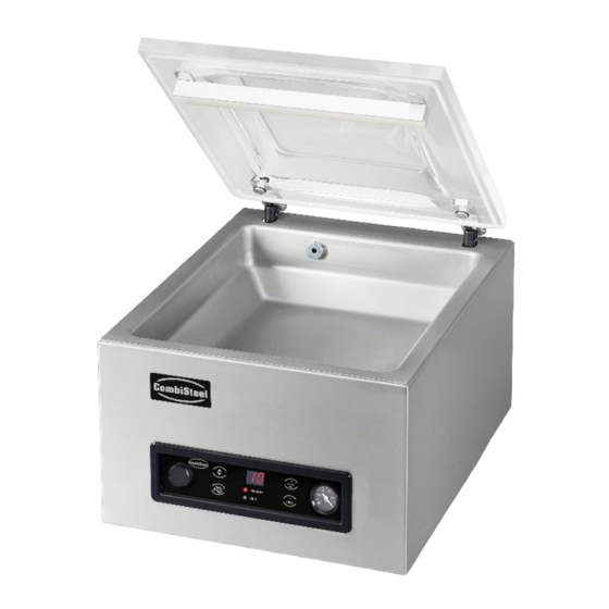
Page 8: Description Of The Machine
Description of the machine This section provides an overview of the main components and functions. If detailed information is available in this manual, you will be referred to the specific sections. Overview of the main components The figure below shows the main components of the system. The model shown may differ from your machine. 1. -
Page 9: Description Of The Packaging Process/Machine Functions
Description of the Packaging Process/Machine Functions This section provides an overview of the packaging process and available machine functions. See Changing the Program Settings on page 15 for information about setting the parameters to the correct values. 4.2.1 Packaging Process/Machine Functions This section describes the packaging process and the machine functions. -
Page 10: Sealing System
Sealing system The sealing system closes the opening(s) of the bag to retain the vacuum and/or gas in the bag. The end of the bag can optionally be cut off by the sealing bar. Figure 2: Overview of the Sealing System 1. -
Page 11: Vacuum Pump
Vacuum pump The vacuum pump creates the vacuum. Figure 3: Overview of the Pump (Pump 3-4 m Figure 4: Overview of the Pump (Pump 8 m Figure 5: Overview of the Pump (Pump 16 m3) 1. Vacuum pump - Creates the vacuum for the process. 2. -
Page 12: Electrical Installation
Electrical installation The electrical installation provides power for the vacuum pump, the seal system and the operation of the machine. See the electrical diagram for the further structure and operation of the electrical installation. Please contact your supplier for the electrical diagram. Only a technical expert may perform work on the electrical installation. -
Page 13: Installation
Installation Consult Technical Data on page 27 for the specifications of the machine. Before installing the machine, carefully read the safety instructions in Safety on page 4. Failure to follow or disregard of the safety instructions may result in serious injury. Transportation and installation The machine must be moved and transported in an upright position. -
Page 14: Operation
Operation It is possible to optimise a program for your products by modifying the parameters of a program, see Changing the Program Settings on page 15. • All persons responsible for the operation of this machine must at least fully read and understand the chapters Safety on page 4 and Operation on page 14. -
Page 15: Starting The Machine
Starting the machine Plug in the machine. Press the on/off button on the control panel to enable the operation. 2 dashes may be shown on the display during the first start-up or ventilation. This means that the machine needs to be decompressed. In this case, open the lid to decompress the machine. Starting the packaging cycle The machine must be started in accordance with Starting the Machine on page 15 before starting a packaging cycle. -
Page 16: 6.6.1.2 Seal
6.6.1.2 Seal This is the time that the sealing wire and/or the cut-off wire are heated. The longer the time, the more heat is transferred to the bag. Use the Cursor key to scroll to the parameter Seal. The LED in front of the selected function will light up. Press the –... -
Page 17: Guideline For Function Values
Guideline for function values Values can be set for each function. In order to understand the consequence of the set value, the table below explains the consequences of giving a low or high value for each function. Function Range Conditions Vacuum 2-99 seconds Rule of thumb: the higher the vacuum, the less oxygen remains... -
Page 18: Maintenance
7 Maintenance When carrying out maintenance work, always observe the following safety rules. Only trained technicians are authorised to perform the described maintenance activities. Always disconnect the power supply by disconnecting the plug. Test the machine after carrying out maintenance work or repairs to make sure the machine can be used safely. -
Page 19: Cleaning The Machine
Cleaning the machine Never clean the machine using a high pressure cleaner. Do not use any aggressive or toxic cleaning agents. Do not use any cleaning agents containing solvents. Clean the surfaces with a soft, damp cloth. You can also apply a cleaning agent to the machine and wash it with clean water. -
Page 20: Pump 3-4 M
7.5.1 Pump 3-4 m The oil exhaust filter prevents oil vapours from being emitted from the vacuum pump with the exhaust air. If the filter becomes saturated, the maximum vacuum level can no longer be reached. Replace the filter in case of vacuuming problems or as specified in Maintenance Schedule on page 18. -
Page 21: Pump 16 M
7.5.3 Pump 16 m Figure 12: Replacing the Oil Exhaust Filter (Pump 16 m3) Follow the steps below to remove the old oil exhaust filter: Remove the filter cover (4) of the vacuum pump (1) and put it aside. Remove the leaf spring (3) and put it aside. Remove the old filter (2). - Page 22 Remove the sealing bar by lifting it from the cylinders. See Figure 13: Removing the Sealing Bar on page 21. Figure 14: Replacing the Sealing Wire Remove the Teflon tape (1) that protects the sealing wire. Remove the screws (2) at the bottom of the sealing bar and remove the sealing wires (3). Replace the Teflon tape on the sealing bar.
-
Page 23: Replacing The Silicone Rubber Of The Silicone Holders
Replacing the Silicone Rubber of the Silicone Holders To ensure a seal of good quality, the silicone rubber may not be damaged and the surface must be smooth. Mechanical contact or burning by the sealing wire may damage the rubber. Replace the silicone rubber if damaged or as specified in Maintenance Schedule on page 18. -
Page 24: Replacing The Lid Gasket
Replacing the Lid Gasket The lid gasket ensures the vacuum chamber is fully closed during the machine cycle. This is essential to reach the maximum vacuum level. Due to extreme pressure differences, the gasket wears and should therefore be replaced regularly. -
Page 25: Troubleshooting
Troubleshooting The tables below show the possible malfunctions and the corresponding causes as well as the steps to be taken. Malfunction Activity More information Control panel does not illuminate. Electrical Installation on page 12. Connect the machine to the power supply. -
Page 26: Terms Of Warranty
Terms of Warranty The warranty is subject to the following limitations. The warranty period for products supplied by Combisteel BV is 3 years from the date indicated on the purchase document. This warranty is limited to manufacturing and machining defects and therefore does not cover breakdowns involving any part of the product that is exposed to any form of wear and tear. -
Page 27: Appendices
Appendices 11.1 Technical data 11.1.1 Technical data Smooth Smooth Smooth Mini Smooth Plus Smooth 30 General Ambient temperature during operation 5 tot 30 °C 5 tot 30 °C 5 tot 30 °C Sound emission < 70 dB(A) < 70 dB(A) <... - Page 28 Smooth Smooth 35 Smooth 42 Smooth 42XL General Ambient temperature during operation 5 tot 30 °C 5 tot 30 °C 5 tot 30 °C Sound emission < 70 dB(A) < 70 dB(A) < 70 dB(A) 5 hrs/day 5 hrs/day 5 hrs/day Maximum daily production Dimensions of the machine Width...
-
Page 29: Logbook
11.2 Logbook This logbook must include: • Annual maintenance work • Major replacements and emergencies • Modifications • Tests of the emergency stop buttons and safety devices Description: Performed by: Date: (nature of the activities, which (authority, technician) parts have been replaced)
Need help?
Do you have a question about the Smooth Mini and is the answer not in the manual?
Questions and answers