Eurovema EUROFLEX Flexmobil i6 User Manual
Hide thumbs
Also See for EUROFLEX Flexmobil i6:
- Service manual (52 pages) ,
- User manual (48 pages) ,
- Manual (41 pages)
Table of Contents
Advertisement
Quick Links
Advertisement
Table of Contents

Related Manuals for Eurovema EUROFLEX Flexmobil i6


Summary of Contents for Eurovema EUROFLEX Flexmobil i6
- Page 1 English User Manual Flexmobil i6 part. no. BRU-i600-02 rev: 04/2021...
-
Page 2: Table Of Contents
35. Transport of electric wheelchair, lifting and attachment points 36. Moving the wheelchair user 37. Reconditioning, reusing, and scrapping 38. Source separation 39. Reconditioning checklist If you are visually impaired: The User Manual is available in a PDF format that can be magnified from www.eurovema.se/dokument. - Page 3 Congratulations on choosing a Flexmobil i6! We hope you will be pleased with this Euroflex product from Eurovema Mobility AB, which has been designed and built in Sweden. The electric wheelchair is designed to satisfy very stringent demands in respect of ergonomics, sitting comfort, and function.
- Page 4 UNPACKING AND ASSEMBLY - Open the packaging and check that it has not suffered any damage during transit. - Also check that the delivery corresponds with the order. If the chair is supplied with the back support and armrests not fitted: •...
- Page 5 • Make sure you tighten all the screws, knobs, and controls properly after making adjustments. • Metal surfaces may get very hot if they are exposed to sunlight or some other external source of heat. • Service, maintenance, and adaptations should be carried out by trained staff authorised by Eurovema Mobility AB.
-
Page 6: Overview Of Different Seat Systems
Overview of different seat systems The Euroflex seat system is designed to deliver optimal sitting comfort to the user. The soft filled cushion is available in a variety of sizes and gives optimal sitting comfort and support to the user. It is upholstered in a dirt-resistant and machine washable polyester fabric. -
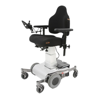
Page 7: Overview, Flexmobil I6 Sitrite
Overview, Flexmobil i6 SitRite 1) control box 2) joystick 3) charging port 4) seat 5) back support 6) armrest 7) automatic fuse 8) drive wheel 9) battery cover 10) swivel wheels 11) footplate 12) seat lifting actuator 13) adjustment knob... -
Page 8: Overview, Flexmobil I6 Comfort
Overview, Flexmobil i6 Comfort 1) control box 2) joystick 3) charging port 4) lifting pillar 5) back support 6) armrest 7) drive wheel 8) battery cover 9) swivel wheels 10) leg support... -
Page 9: Control System, Linx Rem211 And R-Net
Control system, Linx REM211 and R-net Flexmobil i6 is equipped with a control system from either Dynamics Control or PG Drive that controls the power from the batteries to the motors. The wheelchair and its electrical seat functions are controlled using the control box, which is available in two different versions: Linx REM211 and R-net. - Page 10 BACK SUPPORT, SitRite - Seat depth, manual setting Use the wheel (1) to adjust seat depth with back support. Set the desired seat depth by moving the back support backwards or forwards. Move the wheel to its original position to lock. BACK SUPPORT, SitRite–...
- Page 11 BACK SUPPORT, Comfort – Seat depth, manual setting To adjust seat depth and back support: Undo the two hex screws holding the actuator in position and the for hex screws holding the back support to the seat frame. Set the desired seat depth by moving the back support backwards or forwards to the required position.
-
Page 12: Back Support, Sitrite - Height Adjustment, Manual Setting
BACK SUPPORT, SitRite - height adjustment, manual setting Undo the safety screws (3, 4) using an Allen key before adjusting the height of the back support (1). Loosen the lever (2) by turning it anticlockwise a ½ turn. Set the back support to the desired height and turn the lever ½... - Page 13 SEAT TILT, SitRite - seat angle, manual setting The seat angle can be adjusted within a range of -14° to +32° backwards. Turn the wheel clockwise to tilt the seat forwards, and anticlockwise to tilt backwards (1). NB Risk of crushing Extra pelvis support To get good support for the pelvis and torso stability, we recommend the use of the SitRite seat system together with a waist belt and thigh support.
-
Page 14: Waist Belt - Fitting
Installation instructions, waist belt Waist belt for adults, Item 80151800... -
Page 15: Seat Height, Sitrite And Comfort - Electronic Setting
SEAT HEIGHT, SitRite and Comfort - electronic setting The seat can be raised and lowered steplessly to any height, and the selected hight will be automatically locked in. Start the wheelchair electronics by pressing the on/off button (1). LINX REM211 Select “seat lift symbol”... -
Page 16: Seat Tilt, Sitrite And Comfort - Electronic Setting
SEAT TILT, SitRite and Comfort - electronic setting If the seat is equipped with electronic seat angling/tilt, this function is activated via the control box. LINX REM211 Select “seat tilt” (7) by pressing the up or down arrow in the seat function button cluster (6), or by moving the joystick (5) to the right or left until the “seat tilt symbol”... -
Page 17: Back Support Angle, Sitrite And Comfort - Electronic Setting
Back support angle, SitRite and Comfort - electronic setting If the seat is equipped with electronic back support angling, this function is activated via the control box LINX REM211 Select the “back support symbol” (7) by pressing the up or down arrow in the seat function button cluster (6), or by moving the joystick (5) to the right or left until the back support symbol light comes on. -
Page 18: Armrest - Height And Width Adjustment
ARMREST - height and width adjustment To adjust the width between the armrests, loosen the wheel (1). Adjust to the desired width and tighten the wheel. Repeat the procedure for the other armrest. Adjust armrest height by loosening the lever (2). Adjust to the desired height and tighten the lever. -
Page 19: Control Box Holder - Adjustment
CONTROL BOX HOLDER - adjustment The position of the control box can be adjusted by loosening the screws 1, 2 and 3 using a 5 mm Allen key. Loosen screw 1 to adjust depth, and screws 2 and 3 to adjust the angle and height of the control box. Set the desired position and tighten the screws. -
Page 20: Head Rest, Sitrite - Adjustment
HEAD REST, SitRite - adjustment If the chair is equipped with a head rest, the height can be adjusted by loosening the wheel (1). Set the correct height and tighten the wheel. WARNING - RISK OF CRUSHING! When the wheel is loosened, the head rest becomes loose and can quickly fall down. Observe caution when adjusting! NB Risk of crushing! -
Page 21: Head Rest, Comfort - Adjustment
HEAD REST, Comfort - adjustment If the chair is equipped with a head rest, it can be adjusted by loosening the screws (1, 2, 3). Then set the correct height and angle. Tighten the screws. NB RISK OF CRUSHING When the screws are loosened, the head rest may suddenly fall down and forwards. Observe caution when adjusting! Warning, risk of crushing! -
Page 22: Leg Support - Complete Footplate
LEG SUPPORT - complete footplate If the chair is equipped with a complete footplate, its height and lower leg angle are adjusted by loosening screws (1 and 2) using a 5 mm Allen key. Adjust to the desired position and tighten. To adjust depth and footplate angle, loosen screws (3 and 4). -
Page 23: Leg Support - Split Footplates
LEG SUPPORT - split footplates If the chair is equipped with split footplates, their height and lower leg angle are adjusted by loosening screws (2) using a 5 mm Allen key. Adjust to the desired position and tighten. To adjust depth and footplate angle, loosen screws (2). -
Page 24: Operation, Linx / Pg R-Net
LEG SUPPORT - split footplates Linx REM211 Press the up or down arrow in the (6) "seat function selection" button cluster or move the joystick (5) to the right or left until the "leg support symbol" light comes on. Then move the joystick (5) forwards to angle the leg support downwards, and backwards to angle the leg support upwards. - Page 25 OPERATION OF ELECTRIC WHEELCHAIR Turn on the main power and sit comfortably in the chair, allowing the arm with which you shall control the chair to rest on the armrest so that your hand has a comfortable grip of the joystick (5). Initiate the wheelchairs electronics by pressing the on/off button (1), wait a couple of seconds until the battery indicator light (3) stops flashing.
- Page 26 Tips and advice when practising operating the wheelchair It is important that you learn how your electric wheelchair works in different operating situations. Practise is the key to developing your skill in operating the wheelchair. In the beginning, do not practise alone and only in environments where no-one/nothing can be injured or damaged, such as in a taped out area that corresponds to the layout of something like a lift.
-
Page 27: Operation Restrictions For Inclined And Uneven Surfaces
OPERATION RESTRICTIONS for inclined and uneven surfaces NB! Make sure that the seat lift is in its lowest position before operating! NB! Do not turn or cross-brake the wheelchair on an inclined surface. NB! Maximum height for a threshold going forwards is 40 mm, and going backwards 30 This wheelchair is only designed to be used indoors and is built to handle obstacles of up to 40 mm. -
Page 28: Releasing The Brakes
RELEASING THE BRAKES To make it possible to transport the wheelchair on the wheels with the electronics switched off, the brakes/motors must be disconnected. This is done by switching off the electronics and “moving the red lever by the chassis leg adjacent to the rear swivel wheel forwards until the lever locks itself in the forward position”... -
Page 29: Circuit Breaker/Power Switch
CIRCUIT BREAKER/MAIN POWER SWITCH The circuit breaker is located between the protective covers under the seat (1). The circuit breaker trips if a serious electrical fault occurs in the wheelchair. The button travels out about 8 mm and a white line becomes visible. -
Page 30: Charging Batteries
Used batteries should be handed in for recycling. Only use the included original batteries from Eurovema Mobility AB (Yuasa NPC24-12V 24Ah). 1. Connect the charger's contact to the control unit on the chair. It is located on the front of the control unit. - Page 31 GUARANTEE Our products come with a 2-year guarantee against manufacturing defects/damage. Upholstery, wheels, and batteries are not covered by this. Instead, these items come with a 1-year guarantee. Normal wear and tear is not covered by the guarantee. We recommend our customers to use the product in accordance with the user manual.
- Page 32 CARE AND MAINTENANCE You will get more enjoyment from your electric wheelchair if it is cared for correctly. The batteries must be charged, the chair must be washed and dried, the tyres must be checked regularly, and the chair may require a drop of oil in the joints in order to prevent them seizing.
-
Page 33: Technical Data
Technical data Data Class Tested Standard SS-EN 12184:2014 Test date 31.05 2016 Chassis Flexmobil i6 max. User weight 150 kg Drive wheel Centre wheel driven Length 860 mm Length with footplate 990 mm Width 575 mm Weight 97 kg Range, fully charged 15 km max. -
Page 34: Troubleshooting
TROUBLESHOOTING Problem? Remedy! Does the wheelchair refuse to start? Has the circuit breaker tripped? Check the circuit breaker - see manual! Are the batteries flat? Charge the batteries - see manual! Are the cables loose? Contact the Technical Aid Centre! Are the batteries not charging? Has the automatic fuse triggered? Check the circuit breaker - see manual! - Page 35 TRANSPORT OF ELECTRIC WHEELCHAIR When transporting the chair in motor vehicles, it is important that the brakes are engaged. See section “Releasing the brakes”. The chair should be strapped in place with straps. As an accessory, special attachment lugs are available in which attachment straps can be fitted. NB The wheelchair is not designed to allow the user to sit in the chair during transport! You can reduce the transport dimensions of the chair by removing the back support, armrests, and leg support.
- Page 36 Instructions for transferring the wheelchair user • Prepare the location to which the user is to be transferred. • Ask whether the user can help and clearly tell them everything you will do, including during the procedure. • When transferring to a wheelchair, lower the armrest, remove or turn back in order to avoid contact or injury.
- Page 37 Reconditioning and reusing the wheelchair This wheelchair is suitable for reconditioning and reusing. This means that if the wheelchair is no longer used by the original user, it can be renovated for use by another user. If you can no longer use the wheelchair, we strongly recommend that you contact your local authorised supplier to have the chair collected for renovation and reuse.
-
Page 38: Source Separation
Source separation 1. Metals • chassis • swivel wheels, rim • seat cross • lifting pillar (not motor) • actuator (not motors) • armrest tube • joystick holder • leg support • head rest, frame • back support, frame • protective plate, chassis •... -
Page 39: Reconditioning Checklist
Reconditioning checklist for electric wheelchairs for indoor use Electric wheelchair......Serial no.......... User ......................Recommended service interval is once per year, or more often if the user is heavier or spastic, as this may result in the wheelchair being exposed to heavier loads. - Page 40 part. no. BRU-i600-02 rev: 04/2021...
Need help?
Do you have a question about the EUROFLEX Flexmobil i6 and is the answer not in the manual?
Questions and answers