
Related Manuals for UFO IONIC


Summary of Contents for UFO IONIC
- Page 1 PRODUCT USER GUIDE Ionic Track Lighting System Rev: C2 PLEASE READ THIS USER GUIDE BEFORE INSTALLING OPERATING OR PERFORMING MAINTENANCE ON THE LIGHTING SYSTEM 360312...
- Page 2 Always check the output voltage of the driver to ensure correct output voltage prior to powering up the system. The Ionic system is suitable for indoor/dry areas only and must not be installed in damp or wet conditions. IMPORTANT...
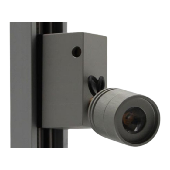
- Page 3 COMPONENTS SPOTLIGHT FITTINGS OVERVIEW There are 3 different spotlight fittings available in the Ionic range. IONIC SX FITTING IONIC MX FITTING IONIC LX FITTING Each fitting is equipped with a local dimming control shown as a circle in above diagrams.
-
Page 4: Track Overview
TRACK OVERVIEW Ionic track is manufactured from aluminium. Supplied as standard in either anodised black or aluminium. Extrusion can be supplied in lengths up to 2800mm. In standard systems the ends of the track are terminated by a power in connector at one end and an end cap at the other. -
Page 5: Control Overview
COMPONENTS CONTROL OVERVIEW We can supply the Ionic system in global dimming and non-dimming versions. Note that all ionic spotlight fittings are locally dimmable via a potentiometer on the fitting body. This works independently of driver type and is available whichever global option is specified. -
Page 6: Installation
INSTALLATION FOR GLOBAL DIMMING SYSTEM (1 TO 4 TRACKS ) CONNECTION FOR NON DIMMING SYSTEM (1 TRACK ) CONNECTION IONIC USER GUIDE... - Page 7 FOR NON DIMMING SYSTEM (2 - 6 TRACKS ) CONNECTION There are 3 steps required to connect up an Ionic system. These are broadly the same irrespective of whether you have a dimming or non dimming system. THE SPOTLIGHT FITTINGS First, the spotlight fittings should be fitted to the track.
-
Page 8: Electrical Information
INSTALLATION ELECTRICAL INFORMATION Ionic spotlight fittings can be added, removed and moved between tracks as long as the overall power capacity of the connected power supply unit is not exceeded. The following tables show the most common configurations of Ionic PSUs / and manual dimmer and highlight the maximum number of fittings that should be connected for each. -
Page 9: Mounting Options Overview
INSTALLATION MOUNTING OPTIONS OVERVIEW There are 4 surface mounting options for Ionic track - C-clips, corner mounting feet, straight magnetic brackets and 45° magnetic brackets. If a recessed mount is required, a channel can be cut to allow the track to be fitted. - Page 10 There are 2 different type of magnetic clips available - straight and 45°. Both are suitable for mounting lengths of track onto a solid magnetic/metallic surface. We recommend a clip is placed approximately every 500mm along the track length as well as at either end. IONIC USER GUIDE...
-
Page 11: Accessories Overview
Secured by the extended snoot. o’ring. If required, use slight screw on motion to help with push-fit. Ionic SX Fitting with Colour filter sits on top of lens (unscrew snoot and fit) UFO LIGHTING... - Page 12 If required, use slight screw on motion to help with push-fit. FOCUSABLE SNOOT ( MX MODELS ONLY ) Focusable Snoot Fitted by unscrewing the standard snoot and replacing with this one. IONIC USER GUIDE...
-
Page 13: Troubleshooting
TROUBLESHOOTING MAINTENANCE LOG Date Maintenance Undertaken Note: A record of all maintenance MUST be kept in the table above, indicating what maintenance was undertaken and when. This MUST be dated for warranty purposes. UFO LIGHTING... - Page 14 System is dead. or other faults. Power LED on interface / splitter / driver is not lit and no light output from Ionic light fittings PSU failed – check output with Replace PSU Track(s) being shorted out by...
- Page 15 NOTES UFO LIGHTING...
- Page 16 United Kingdom • United States • Germany • Europe • Universal Fibre Optics Ltd Universal Fiber Optics USA LLC UFO Licht GmbH Home Place Coldstream 1749 Northgate Blvd Andreasstraße 20 TD12 4DT Sarasota FL34234 93059 Regensburg Deutschland +49 (0)9491 955880...
Need help?
Do you have a question about the IONIC and is the answer not in the manual?
Questions and answers