Table of Contents
Advertisement
Quick Links
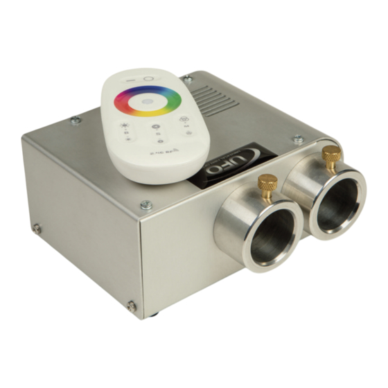
Illuminator
User Guide
MicroLED
Illuminator Range
Models covered by this manual:
UFO MIC4000x2
Please read this manual fully before installing, operating or performing
maintenance on the illuminator unit.
Universal Fiber Optics
6119A Clark Center Avenue | Sarasota | FL34238
Tel: 941 343 8115 | 800 UFO 5554
www.fiberopticlighting.com
Issue 2 | Revised: 170317
Advertisement
Table of Contents

Subscribe to Our Youtube Channel
Related Manuals for UFO MIC4000x2


Summary of Contents for UFO MIC4000x2
- Page 1 Please read this manual fully before installing, operating or performing maintenance on the illuminator unit. Universal Fiber Optics 6119A Clark Center Avenue | Sarasota | FL34238 Tel: 941 343 8115 | 800 UFO 5554 www.fiberopticlighting.com Issue 2 | Revised: 170317...
- Page 2 Please read these instructions fully before connecting your unit to the electrical supply, and keep them for future reference. The UFO MicroLED range of illuminators utilises an RGBW LED array and is suitable for use with either glass or polymer fiber-optic harness The MicroLED is powered by a 100-240 VAC remote desktop power supply unit.
- Page 3 INSTALLATION INSTRUCTIONS POWER SUPPLY REQUIREMENTS The LED Illuminator is powered from a multifunction, multi-voltage, desk top Power Supply Unit. Remove the SW4047B Desk Top PSU from its box. This PSU is a multi- plug device catering for UK, European and USA plugs. Select the correct plug and slide it into the receptacle until it clicks securely into place as shown below: The plug can be removed by squeezing together the plastic retaining lugs and...
- Page 4 Plug the mains plug into the electrical supply socket. Switch on power the led Indicator will illuminate and the illuminator will start up automatically. If no light is produced consult the TROUBLESHOOTING section NOTE: THESE ILLUMINATORS ARE NOT MAINS DIMMABLE. MIC4000x2 REMOTE CONTROLLER Specification: Description Details...
-
Page 5: Remote Controller Operation
REMOTE OPERATION 2. OFF 1. ON 4. Indicator Light 3. Color Ring 5. Speed 9. Mode 6. Brightness 10. Mode 7. Brightness 8. Speed Description Function Button Power ON Button Power OFF Color Ring Touch control all colors (White not available) Indicator Indicates Controller active when buttons pressed Button... - Page 6 Mode Function Programme List Mode Brightness Speed Comment To revert to 1 (Static White) at any Static White Adjustable Not Adjustable time touch Color Ring then Mode+ Color Ring control – brightness White and Colors adjust Color only, not White. To Adjustable Not Adjustable mixed...
-
Page 7: Stand-Alone Operation
REMOTE RANGE WALK TEST Once the Illuminator is fully installed carry out a complete range walk test and record the range in the table below. This information is essential for maintenance purposes to determine if the range/sensitivity is reducing and also to record dead areas within the Remote Controller’s range due to RF obstructions and/or RF interference. -
Page 8: Dmx Operation
The Illuminator is controlled using the 2 push buttons on the rear of the unit. The Lower button STOPS and STARTS the color Cycle The Upper button is used to select the Cycle speed as follows. Push the Lower button repeatedly until the color White is displayed. -
Page 9: Maintenance
MAINTENANCE Please note that a record of all maintenance MUST be kept in the table below, indicating what maintenance was undertaken and when. This MUST be dated for warranty purposes. Date Maintenance Undertaken Universal Fiber Optics... -
Page 10: Technical Specifications
TECHNICAL SPECIFICATIONS Problem Probable cause(s) Remedy Mains supply off Check supply and reinstate Unit is dead - LED power Loose mains plugs Check plugs indicator is not illuminated PSU failed Replace PSU LED array failure Replace Iluminator Unit is dead - no light output but LED power indicator is still May have been switched off... - Page 11 TECHNICAL SPECIFICATIONS Description Details Port connector size 2 x 1.18” (30mm) Fiber type Glass/PMMA Supply voltage 110-240 VAC, 47-63Hz, 0.58A PSU Output 12V DC, 2A, 24W Maximum LED Power 4 - 10W in color cycle mode Min Ambient Temperature 14°F (-10ºC) 113°F (+45ºC) Max Ambient Temperature Power Connection...
- Page 12 Universal Fiber Optics 6119A Clark Center Avenue | Sarasota | FL34238 Tel: 941 343 8115 | 800 UFO 5554 www.fiberopticlighting.com...
Need help?
Do you have a question about the MIC4000x2 and is the answer not in the manual?
Questions and answers