Avaya 4826GTS Installing Manual
Ethernet routing switch 4800 series
Hide thumbs
Also See for 4826GTS:
- Fundamentals (108 pages) ,
- Technical configuration manual (59 pages) ,
- Quick installation (2 pages)

Subscribe to Our Youtube Channel
Related Manuals for Avaya 4826GTS


Summary of Contents for Avaya 4826GTS
- Page 1 Installing Avaya Ethernet Routing Switch 4800 Series Release 5.8 NN47205-300 Issue 07.02 August 2016...
- Page 2 RESERVES THE RIGHT TO TAKE LEGAL ACTION AGAINST YOU the express behalf of Avaya. End User agrees to indemnify and hold AND ANYONE ELSE USING OR SELLING THE SOFTWARE harmless Avaya, Avaya's agents, servants and employees against all WITHOUT A LICENSE.
- Page 3 LICENSED TO PROVIDE AVC VIDEO. NO LICENSE IS GRANTED written consent of Avaya can be a criminal, as well as a civil offense OR SHALL BE IMPLIED FOR ANY OTHER USE. ADDITIONAL under the applicable law.
-
Page 4: Table Of Contents
.................... 16 Console port pin assignments ...................... 17 Universal Serial Bus ports ...................... 18 Power specifications Avaya Ethernet Routing Switch 4826GTS, 4826GTS-PWR+, 4850GTS, and 4850GTS- .......................... 18 PWR+ ............. 19 Power over Ethernet Plus power supply power specification ................... 20 Installing the switch power supply ........................ -
Page 5: Chapter 1: Introduction
This document provides conceptual information and installation procedures for the switch hardware. Note: Release 5.8 is supported only on ERS 4800. Avaya Ethernet Routing Switch 4800 The following table describes the 4800 series of Avaya Ethernet Routing switches. Table 1: 4800 Series Switch Platforms 4800 Series Switch Model Key Features... -
Page 6: Chapter 2: New In This Release
Other changes See the following section for information about changes that are not feature-related. Title change for documents Installing Avaya Ethernet Routing Switch 4000 Series is renamed Installing Avaya Ethernet Routing Switch 4800 Series. Introduction chapter Information about Related resources and Support are moved to the last chapter in this document. -
Page 7: Chapter 3: Installing The Avaya Ethernet Routing Switch
Caution: To protect the Avaya Ethernet Routing Switch against ESD damage, take the following measures before you connect data cables to the device: • Always use antistatic wrist straps. Make sure you adjust the strap to provide good skin contact. -
Page 8: Environmental Requirements
• Do not remove the wrist or ankle strap until the installation is complete. Preventing electrostatic damage in new cable installations With new cable installations, Avaya recommends that you use an ESD discharge cable to reduce the potential for damage from static, that can build up in cables. The following figure illustrates an ESD cable. -
Page 9: Package Contents
The following figure illustrates the components that are provided with each switch. If any components are missing, contact the switch vendor. Note: Avaya switch hardware can vary in size and shape. Your switch might appear different than the following example figure. August 2016 Installing Avaya ERS 4800 Series Comments on this document? infodev@avaya.com... -
Page 10: Installing The Switch On A Table Or Shelf
Installing the Avaya Ethernet Routing Switch Figure 2: Package contents 1. Avaya Ethernet Routing Switch unit 2. Rack-mounting hardware that includes: • Rack-mount brackets • Screws to attach brackets to the switch • Screws to attach the switch to the equipment rack 3. - Page 11 Translations of safety messages on page 45. Note: Avaya switch hardware can vary in size and shape. Your switch might appear different than the following example figures. 1. Attach the included rubber footpads on the bottom of the switch at the locations.
-
Page 12: Installing The Switch In An Equipment Rack
45. Note: Avaya switch hardware can vary in size and shape. Your switch might appear different than the following example figures. 1. Attach a bracket to each side of the switch using a #2 Phillips screwdriver as illustrated in below. -
Page 13: Cable Requirements
The interconnect cabling must conform to the Cat5e, Cat6, or Cat6e specification of the Commercial Building Telecommunications Cabling Standard, ANSI/TIA/EIA 568-B fitted with an RJ-45 Module jack. Table continues… August 2016 Installing Avaya ERS 4800 Series Comments on this document? infodev@avaya.com... -
Page 14: Installation And Removal Of Small Form-Factor Pluggable Transceivers
WAN speed. The system uses this value for STP path cost and MLT utilization. Avaya recommends that you enable egress traffic shaping on the port to 1.544 Mbps when using the T1 SFP to guarantee appropriate Quality of Service and traffic prioritization. - Page 15 1. Disconnect the network fiber cable from the transceiver. 2. Use the locking mechanism on the transceiver to release it. The locking mechanism varies from model to model as illustrated below. August 2016 Installing Avaya ERS 4800 Series Comments on this document? infodev@avaya.com...
-
Page 16: Rj-45 Connector Pin Assignments
Not applicable Not applicable Important: The Avaya ERS 4800 PWR+ models use pins 1, 2, 3, and 6 for PoE Plus, and is compliant with Type 2 (MDI-X) in IEEE802.3at. Console port pin assignments The following table describes the console port pin assignments. -
Page 17: Universal Serial Bus Ports
The restore factory-default command resets the switch or stack to its default configuration. To reset the switch or stack to its default configuration perform the following procedure. 1. Enter restore factory-default. The following message appears: August 2016 Installing Avaya ERS 4800 Series Comments on this document? infodev@avaya.com... -
Page 18: Power Specifications
Avaya Ethernet Routing Switch 4826GTS, 4826GTS-PWR+, 4850GTS, and 4850GTS-PWR+ The following table describes the regulatory AC power specifications for the ERS 4826GTS, 4826GTS–PWR+, 4850GTS, and 4850GTS-PWR+ switches. It must be noted that regulatory power specifications are based on the maximum rated capacity of the power supplies and are not based on typical power consumption which is typically lower. -
Page 19: Power Over Ethernet Plus Power Supply Power Specification
PWR+ models support dual 54V 1000W Power over Ethernet Plus (PoE+) AC power supplies. Figure 3: 1000W power supply The ERS 4826GTS and ERS 4850GTS support 300W AC power supplies. Figure 4: 300W power supply The 300W and 1000W AC power supplies use an IEC 60320 C16 AC power cord connector. The... -
Page 20: Installing The Switch Power Supply
Installing the Avaya Ethernet Routing Switch Figure 5: IEC 60320 C16 connector Power over Ethernet Plus specifications Model Maximum PoE W Average PoE W on 26 Average PoE W on 50 port models port models ERS 4800 PWR+ models 855W with one power 15.4W (802.3af) -
Page 21: Connect Ac Power
• CSA-certified (CSA label secured to the cord) United Kingdom: • 240VAC • BS1363 male plug with fuse • 50 Hz • Harmonized cord • Single phase Table continues… August 2016 Installing Avaya ERS 4800 Series Comments on this document? infodev@avaya.com... - Page 22 Installing the Avaya Ethernet Routing Switch Country and Plug Specification Specifications Typical Plug Australia: • 240VAC • AS3112-1981 male plug • 50 Hz • Single phase Danger: Using power cords with a proper grounding path Use only power cords that have a grounding path. Without a proper ground, a person who touches the switch is in danger of receiving an electrical shock.
-
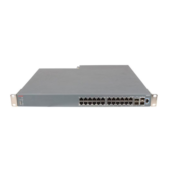
Page 23: Check Light Emitting Diode On The Switch
Switch LED state indicators on page 25 • Port LED state indicators on page 26 Figure 7: Avaya Ethernet Routing Switch 4826GTS 1. USB Port 4. Shared SFP ports and SFP+ ports. SFP ports can support low speed 100FX SFP 2. Switch LEDs 5. - Page 24 Installing the Avaya Ethernet Routing Switch Figure 8: Avaya Ethernet Routing Switch 4826GTS-PWR+ 1. USB Port 4. Shared SFP ports and SFP+ ports. SFP ports can support low speed 100FX SFP 2. Switch LEDs 5. Console Port 3. 10/100/1000 PoE+ ports (LEDs above ports) Figure 9: Avaya Ethernet Routing Switch 4850GTS 1.
-
Page 25: Switch Led State Indicators
Check the switch logs. No Stack up/down connection is present, or the switch is in stand-alone mode. Table continues… August 2016 Installing Avaya ERS 4800 Series Comments on this document? infodev@avaya.com... -
Page 26: Port Led State Indicators
The port is set to operate at 1000 Mb/s and no PoE power is delivered on the port, on ERS 4800 non-PoE models (4826GTS, 4850GTS) or ERS 4800 PoE models without a PoE consumer attached to the port (4826GTS-PWR+, 4850GTS- PWR+). - Page 27 Check Light Emitting Diode on the switch Label Color and Status Description consumer attached to the port (4826GTS-PWR+, 4850GTS- PWR+). Amber, Green Pulse The port is experiencing a PoE error. When the Link/Activity LED is green and the Speed LED is off, the port is set to operate at 10 Mb/s for all ERS 4800 models (4826GTS-PWR+, 4850GTS-PWR+, 4826GTS, 4850GTS).
-
Page 28: Set Ip Parameters For The Switch
Installing the Avaya Ethernet Routing Switch establish a link. Connect ports using the same set speed or use auto-negotiation on each switch. Set IP parameters for the switch After the switch starts up and initializes all software modules, it begins switching operations. - Page 29 4. When the switch configuration is set to factory default the following screen appears. Enter the information requested at each prompt. Welcome to the 4826GTS-PWR+ setup utility. You will be requested for information to initially configure for the switch. When finished the information will be applied and stored in the switch NVRAM.
- Page 30 Important: The switch only supports the Avaya CLI, the old 'Bay Stack' menu interface is not supported on this product. When the switch is set to factory default parameters, the CLI Quickstart appears which enables you to set default IP information.
-
Page 31: Set Ip Parameters Using Ip.cfg File On A Usb Memory Device
USB. Example: customer1.cfg USBagent <string> NEXTIP, NEXTMask, Specifies the filename of the agent image to load from the USB and NEXTGateway and specifies IPs for next boot. Example: ers4800/4800_580004.img August 2016 Installing Avaya ERS 4800 Series Comments on this document? infodev@avaya.com... - Page 32 Installing the Avaya Ethernet Routing Switch Note: If you download an ASCII file or diag/image with an Ip.cfg file, the specific ASCII file or diag/ image must be present on the usb device. The ip.cfg file loads information from the ASCII configuration file in order of precedence. For example, if you have an ip.cfg file with the following commands:...
- Page 33 If you have a console connected to the switch / stack, then while the system retrieves the ip.cfg file from the USB memory device, the Avaya banner page appears. If you use the serial console while the system is restarting or within the first few minutes after booting, then the switch will not load the IP.CFG file.
-
Page 34: Set Ip Parameters Using Bootp
Installing the Avaya Ethernet Routing Switch Set IP parameters using bootp The switch is configured to obtain a management IP address using BOOTP by default If the switch is connected to the network and an appropriate bootp server is configured, then the server assigns an IP address to the switch. -
Page 35: Stacking
3. Base Unit Select Switch — used to designate the Base Unit in a stack. When set to the Right position, this unit acts as the Base Unit for the stack August 2016 Installing Avaya ERS 4800 Series Comments on this document? infodev@avaya.com... - Page 36 Installing the Avaya Ethernet Routing Switch Unit Select switch Use the Unit Select switch to designate a switch in the stack as the base unit. Slide the Unit Select switch to the right to designate a switch as the base unit. You can designate only one switch in a stack as the base unit;...
- Page 37 3, this continues until the maximum stack configuration (up to eight units) is reached. If another unit in the stack is designated as the base unit, the new base unit keeps its originally designated unit number in the stack. August 2016 Installing Avaya ERS 4800 Series Comments on this document? infodev@avaya.com...
- Page 38 Installing the Avaya Ethernet Routing Switch Stack MAC address When a switch participates in a stack configuration, stack initialization automatically assigns a stack MAC address. The stack MAC address is the base unit MAC address plus 1. If another unit in the stack is assigned as the base unit, the new stack MAC address is the MAC address of the new base unit plus 1.
- Page 39 This means that the agent code image, on a replacement unit, is automatically upgraded or downgraded to match the software running on the stack. In August 2016 Installing Avaya ERS 4800 Series Comments on this document? infodev@avaya.com...
-
Page 40: Stack Configurations
Because stack parameters are associated with the base unit, the physical stack order depends on the base unit position and whether you configure the stack cascade up (stack up) or cascade down (stack down). This designation depends on the stack cabling arrangement. Avaya recommends that you use Cascade Down configuration. - Page 41 Stack configurations (stack down) direction. The following illustration demonstrates a typical cascade down (stack down) configuration. Figure 15: Cascade Down (Stack Down) configuration August 2016 Installing Avaya ERS 4800 Series Comments on this document? infodev@avaya.com...
- Page 42 Important: Because many network management software packages assume a cascade down (stack down) configuration, Avaya recommends that you use a cascade down configuration. Cascade up In a cascade up (stack up) configuration, the base unit is physically the bottom unit in the stack. The cable connected to the Cascade Up connector of the base unit terminates in the Cascade Down connector of the last unit physically at the top of the stack.
- Page 43 Stack configurations Figure 16: Cascade Up (Stack Up) configuration August 2016 Installing Avaya ERS 4800 Series Comments on this document? infodev@avaya.com...
- Page 44 Installing the Avaya Ethernet Routing Switch Important: Because many network management software packages use a cascade down (stack down) configuration, Avaya recommends that you use a cascade down configuration. See Cascade down on page 40. Enterprise Device Manager always shows the physical view in a cascade down (stack down) configuration.
-
Page 45: Chapter 4: Translations Of Safety Messages
Se il dispositivo viene installato in un rack, non impilare le unità direttamente una sull'altra. Ogni unità deve essere fissata al rack con le staffe di montaggio appropriate. Le staffe di montaggio non sono state progettate per supportare più unità. August 2016 Installing Avaya ERS 4800 Series Comments on this document? infodev@avaya.com... - Page 46 Se nello slot non vengono installati moduli, assicurarsi di mantenere la piastra di copertura metallica in sede sopra lo slot. La rimozione della piastra impedisce la ventilazione e il corretto raffreddamento dell'unità. August 2016 Installing Avaya ERS 4800 Series Comments on this document? infodev@avaya.com...
- Page 47 Use only power cords that have a grounding path. Without a proper ground, a person who touches the switch is in danger of receiving an electrical shock. Lack of a grounding path to the switch can result in excessive emissions. Important: Vorsicht: August 2016 Installing Avaya ERS 4800 Series Comments on this document? infodev@avaya.com...
- Page 48 Senza un'adeguata messa a terra, chiunque tocchi lo switch corre il rischio di ricevere una scossa elettrica. L'assenza di un percorso per la messa a terra verso lo switch può comportare un eccesso di emissioni. August 2016 Installing Avaya ERS 4800 Series Comments on this document? infodev@avaya.com...
Need help?
Do you have a question about the 4826GTS and is the answer not in the manual?
Questions and answers