
Subscribe to Our Youtube Channel
Related Manuals for Compaq ProSignia 200 6/233


Summary of Contents for Compaq ProSignia 200 6/233
- Page 1 ......ProSignia 200 6/233 Server Setup and Installation Guide Third Edition (October 1997)
- Page 2 MERCHANTABILITY, FITNESS FOR PARTICULAR PURPOSE, GOOD TITLE AND AGAINST INFRINGEMENT. This publication contains information protected by copyright. No part of this publication may be photocopied or reproduced in any form without prior written consent from Compaq Computer Corporation. 1997 Compaq Computer Corporation.
-
Page 3: Table Of Contents
Rear Panel Connectors ..................1-3 Network Controller ....................1-5 Drive Positions ...................... 1-5 Processor Board..................... 1-6 System Memory ....................1-7 Expansion Slots ..................... 1-7 IDE Enhanced Disk Controller ................1-7 Network Controller ....................1-8 Compaq ProSignia 200 6/233 Setup and Installation Guide... - Page 4 ......Compaq ProSignia 200 6/233 Features Continued Video Controller....................1-8 ROM ........................1-8 Power Supply ......................
- Page 5 Installing Hardware Options Continued Installing an Expansion Board ................3-8 Replacing the Expansion Backplane Brace............3-10 Installing a Processor in Your ProSignia 200 6/233 Server........3-11 Removing the System Board Tray ..............3-11 Replacing the Processor ..................3-13 Removing the Processor..................3-13 Installing the Processor ..................
- Page 6 Loading Compaq Device Drivers................5-11 Compaq NetWare and IntranetWare Device Drivers.......... 5-12 Windows NT Device Drivers from Compaq ............5-14 SCO OpenServer and SCO UnixWare Device Drivers from Compaq ....5-15 SCO OpenServer ....................5-16 UnixWare ......................5-16 IBM OS/2 Device Drivers from Compaq ............5-16 Banyan VINES Device Drivers from Compaq ..........
- Page 7 Jumper Settings......................D-5 Appendix E Regulatory Compliance Notices Federal Communications Commission Notice.............E-1 Modifications......................E-1 Cables ........................E-2 Declaration of Conformity for Products Marked with the FCC Logo-United States only ..................E-2 Canadian Notice (Avis Canadien) ................E-2 Compaq ProSignia 200 6/233 Setup and Installation Guide...
- Page 8 Laser Safety Warnings ..................E-4 Compliance with CDRH Regulations ..............E-4 Compliance with International Regulations............E-4 Laser Product Label....................E-5 Laser Information ....................E-5 Battery Replacement Notice..................E-6 Battery Recycling Notice .....................E-6 Appendix F Specifications and Connector Interfaces ProSignia 200 6/233 Specifications ................F-1 Connector Interfaces..................... F-2 Index...
-
Page 9: Preface
Appendix C Power Cord Set Requirements This appendix contains requirements for the power cord set now available with the ProSignia 200 6/233 servers. A table lists power cord set requirements for each country. Compaq ProSignia 200 6/233 Setup and Installation Guide... -
Page 10: Text Conventions
......Preface Appendix D Switches and Jumpers This appendix provides the correct settings for the switches on the System board and riser boards. -
Page 11: Symbols In Text
If this surface is contacted, the potential for injury exists. To reduce risk of injury from a hot component, allow the surface to cool before touching. Compaq ProSignia 200 6/233 Setup and Installation Guide... -
Page 12: For More Information
For More Information Contact your nearest Authorized Compaq Reseller or Service Provider for more information. In the United States, call 1-800-345-1518. In Canada, call 1-800-263-5868. -
Page 13: Online Help
Users can download drivers, patches, and Compaq service updates from the following sources: Online services such as CompuServe, Prodigy, and America Online can be used if you are a member. Use the keywords to access Compaq materials: Compuserve- The keywords are “GO COMPAQ.”... -
Page 14: Compaq Cds
Locator (URL): http://www.compaq.com. Compaq Download Facility: Call 1-281-518-1418 Compaq CDs Compaq Systems Reference Library CD Compaq Systems Reference Library CD is located in the Reference Information pack and includes the following online documents: Diagnostics Insight Manager documentation Integration TechNotes Part number lists... -
Page 15: Other Hardcopy Documents
......Compaq SmartStart and Support Software CD Compaq SmartStart and Support Software CD is located in the Server Setup and Management pack and contains: System Configuration Utility software... -
Page 16: Compaq Authorized Reseller Or Service Provider
......Preface Compaq Authorized Reseller or Service Provider Compaq Worldwide Technical Support Telephone Numbers Location Voice 65-7503030... -
Page 17: Customer Support
Compaq servers for advanced networks. Download TechNotes from the Systems Reference Library CD. Getting Product Updates The latest product updates are available on the Internet at the Compaq World Wide Web site. Access the site through the following address: http://www.compaq.com... -
Page 18: Compaq Prosignia 200 6/233 Features
Appendix C Power Cord Set Requirements This appendix contains requirements for the power cord set now available with the ProSignia 200 6/233 servers. A table lists power cord set requirements for each country. Compaq ProSignia 200 6/233 Setup and Installation Guide... - Page 19 ......Preface Appendix D Switches and Jumpers This appendix provides the correct settings for the switches on the System board and riser boards.
- Page 20 If this surface is contacted, the potential for injury exists. To reduce risk of injury from a hot component, allow the surface to cool before touching. Compaq ProSignia 200 6/233 Setup and Installation Guide...
- Page 21 For More Information Contact your nearest Authorized Compaq Reseller or Service Provider for more information. In the United States, call 1-800-345-1518. In Canada, call 1-800-263-5868.
- Page 22 Users can download drivers, patches, and Compaq service updates from the following sources: Online services such as CompuServe, Prodigy, and America Online can be used if you are a member. Use the keywords to access Compaq materials: Compuserve- The keywords are “GO COMPAQ.”...
- Page 23 Locator (URL): http://www.compaq.com. Compaq Download Facility: Call 1-281-518-1418 Compaq CDs Compaq Systems Reference Library CD Compaq Systems Reference Library CD is located in the Reference Information pack and includes the following online documents: Diagnostics Insight Manager documentation Integration TechNotes Part number lists...
- Page 24 ......Compaq SmartStart and Support Software CD Compaq SmartStart and Support Software CD is located in the Server Setup and Management pack and contains: System Configuration Utility software...
- Page 25 ......Preface Compaq Authorized Reseller or Service Provider Compaq Worldwide Technical Support Telephone Numbers Location Voice 65-7503030...
- Page 26 Compaq servers for advanced networks. Download TechNotes from the Systems Reference Library CD. Getting Product Updates The latest product updates are available on the Internet at the Compaq World Wide Web site. Access the site through the following address: http://www.compaq.com...
-
Page 27: Industry Support
Compaq ProSignia 200 6/233 Features The Compaq ProSignia 200 6/233 server uses high-performance processor and I/O technologies to give you maximum performance and flexibility. It is the only server that delivers true server functionality at the price of a desktop PC. -
Page 28: Comprehensive Customer Support
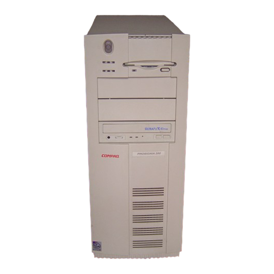
Compaq servers for advanced networks. You can print TechNotes from the Systems Reference Library CD. Standard Features The following features are standard on all Compaq ProSignia 200 6/233 models, unless otherwise noted. Front Panel Components The following illustration and table show and describe the components on the front panel of the server. -
Page 29: Rear Panel Connectors
Rear Panel Connectors The following illustration and table show and describe the connectors and switches on the rear panel of the server. Each connector includes an icon to help you identify its function. Compaq ProSignia 200 6/233 Setup and Installation Guide... - Page 30 Serial Port A Serial Port B Parallel Port Video RJ45 Network BNC Network Figure 1-3. ProSignia 200 6/233 rear panel connectors and switches Table 1-2 Rear Panel Connectors Connectors Function Power Cord Connects the server to an electrical power outlet.
-
Page 31: Network Controller
10BaseT Ethernet (module upgradable to 100TX) and a BNC connector for 10Base2 Thinnet Ethernet. Drive Positions The ProSignia 200 6/233 server can house up to five mass storage devices. The following table and illustration describe the recommended drive configurations. Compaq ProSignia 200 6/233 Setup and Installation Guide... -
Page 32: Processor Board
......Compaq ProSignia 200 6/233 Features Figure 1-4. ProSignia 200 6/233 server drive positions Table 1-3... -
Page 33: System Memory
The system ships standard with 32 MB (two 16-MB SIMMs) of EDO memory. IMPORTANT: ECC-capable FastPage Mode (FPM) memory can be purchased as an option kit from Compaq. The ProSignia 200 6/233 does not support the mixing of EDO and FPM memory. -
Page 34: Network Controller
The video controller (graphics card) in the Compaq ProSignia 200 6/233 server has sockets for a memory upgrade from 1 megabyte of video RAM to 2 megabytes of video RAM. Compaq does not offer this upgrade and does not offer support for it. -
Page 35: Server Management And Configuration
......Server Management and Configuration Compaq offers an extensive set of features and optional tools to support effective server management and configuration. These features fall into the categories listed below and are described in this guide:... -
Page 36: Automatic Server Recovery-2 (Asr-2)
......1-10 Compaq ProSignia 200 6/233 Features Remotely control servers, if this option is set... -
Page 37: Getting Additional Configuration Information
......1-11 Getting Additional Configuration Information The latest product updates are available on the Internet at the Compaq World Wide Web site. Access the site through the following address: http://www.compaq.com Upgrading ECC Memory... -
Page 38: Server Installation Overview
Chapter 2 Server Installation Overview The following instructions are provided for first-time installations and for hardware option upgrades. If you have any problems, contact your Compaq Authorized Reseller. WARNING: To reduce the risk of electric shock or damage to the equipment: Do not disable the power cord grounding plug. -
Page 39: Overview Of Installing The Server
Ordering SmartStart Activation Keys. If you are purchasing an operating system from Compaq (optional), you should order the SmartStart Activation Keys now, so that you will receive the keys by the time you are ready to install the OS. For ordering information, refer to the Server Setup and Management pack shipped with your server. -
Page 40: Selecting A Site And Unpacking The Server
SmartStart CD initialization procedures, refer to the server Setup and Management pack shipped with your server. Installing Compaq Insight Manager. Use this utility to manage your server. For Compaq Management CD initialization procedures, refer to the server Setup and Management pack shipped with your server. -
Page 41: Installing Hardware Options And Setting Switches
......2-4 Installing the Server WARNING: To reduce the risk of electric shock or damage to the equipment: Do not disable the power cord grounding plug. -
Page 42: Removing The Side Access Panel
If the computer is on, turn it off and disconnect the power cord. Disconnect any other external equipment connected to the computer. Remove the three thumbscrews on the rear of the unit. Compaq ProSignia 200 6/233 Setup and Installation Guide... -
Page 43: Replacing The Side Access Panel
......2-6 Installing the Server Slide the side access panel toward the rear of the unit. (See the Figure below.) Lift and remove the panel. - Page 44 ......Figure 2-2. Securing the system with a user-supplied padlock Compaq ProSignia 200 6/233 Setup and Installation Guide...
- Page 45 ......2-8 Installing the Server Removing the Front Bezel To gain access to the hard drive and removable media you must remove the front bezel: Remove the side access panel.
-
Page 46: Installing Hardware Options
WARNING: To reduce the risk of personal injury from hot surfaces, allow the internal system components to cool before touching. Compaq ProSignia 200 6/233 Setup and Installation Guide... -
Page 47: Pre-Failure Warranty
Refer to Appendix A, “Electrostatic Discharge,” for more information. Pre-Failure Warranty Pre-Failure Warranty is supported by your server if you run Compaq Insight Manager and purchase the optional FPM ECC memory, or if you purchase hard drives from Compaq through a Compaq Authorized Reseller. Supported... -
Page 48: Disabling The Power Switch Security Feature
Remove the side access panel. (See chapter 2.) Remove the front bezel. (See chapter 2.) Locate the two clips securing the switch in the front bezel on the rear side of the bezel assembly. Compaq ProSignia 200 6/233 Setup and Installation Guide... - Page 49 ......Installing Hardware Options Use a narrow instrument to release each clip from the bezel ;...
-
Page 50: Installing Expansion Boards
Replace the front bezel. Replace the Side Access Panel. Installing Expansion Boards The ProSignia 200 6/233 server contains five expansion slots: Three dedicated PCI local bus expansion slots (slots 1, 2, and 3); the Video card occupies slot 3. IMPORTANT: In SCSI models slot 2 is occupied by a preinstalled PCI Wide-Ultra SCSI Controller. -
Page 51: Removing The Expansion Backplane Brace
PCI Slot 2 PCI Slot 3 Shared PCI/ISA Slot 4 ISA Slot 5 Figure 3-4. Locating ProSignia 200 6/233 expansion board slots Removing the Expansion Backplane Brace CAUTION: Before an expansion board can be installed or replaced, you must remove the expansion backplane brace that holds the expansion cards. -
Page 52: Removing An Expansion Slot Cover
Figure 3-5. Removing the expansion backplane brace Removing an Expansion Slot Cover To install a PCI or an ISA expansion board, complete the following steps: Locate the correct vacant slot in the expansion board. Compaq ProSignia 200 6/233 Setup and Installation Guide... -
Page 53: Installing Hardware Options
......Installing Hardware Options Remove the screw from the expansion slot cover, then remove the expansion slot cover. - Page 54 ......Replace the screw at the side of the expansion slot. Figure 3-7. Sliding an expansion board into the expansion slot Replace the expansion board cage into the server chassis. Compaq ProSignia 200 6/233 Setup and Installation Guide...
-
Page 55: Replacing The Expansion Backplane Brace
......3-10 Installing Hardware Options Replacing the Expansion Backplane Brace Grasp the expansion backplane brace at both ends and push it into the server chassis. -
Page 56: Installing A Processor In Your Prosignia 200 6/233 Server
CAUTION: Installing the processor upgrade incorrectly may cause damage to the processor board. Compaq recommends that you have a Compaq Authorized Reseller or Service Provider install the processor upgrade. If you plan to install it yourself, read all the instructions carefully before you begin. - Page 57 ......3-12 Installing Hardware Options Figure 3-9. Removing the system board tray To remove the system board tray, follow these steps: Shut down all programs and the operating system.
-
Page 58: Replacing The Processor
Unplug the thermistor cable from header P1005 on the system board. NOTE: Clicking once releases the tabs, clicking twice locks the tabs open. Figure 3-10. Unplugging the thermistor cable from the System board Compaq ProSignia 200 6/233 Setup and Installation Guide... - Page 59 ......3-14 Installing Hardware Options 2. Push the locking tabs in on either end of the Pentium II processor. Push til you hear two clicks to lock the tabs in the open position.
-
Page 60: Installing The Processor
Figure 3-13. Inserting the Pentium II Processor into the processor connector 2. Pull the processor tabs outward. The tabs will click twice, indicating that the processor is locked to the system board. Compaq ProSignia 200 6/233 Setup and Installation Guide... - Page 61 ......3-16 Installing Hardware Options Figure 3-14. Pull the Pentium II processor tabs outward to lock the processor to the system board 3.
-
Page 62: Installing A Memory Upgrade On The Video Graphics Board
Installing a Memory Upgrade on the Video Graphics Board The video graphics card in the Compaq Prosignia 200 6/233 server has sockets for a memory upgrade from 1 Megabyte of video RAM to 2 Megabytes of Video RAM. Compaq does not offer this upgrade and does not offer support for To upgrade the memory contact the Video Graphics Card vendor, STB Systems Inc., directly by calling the technical support desk phone number,... - Page 63 ......3-18 Installing Hardware Options Figure 3-16. Removing the graphics board from the expansion slot 4.
-
Page 64: Adding Memory To The Prosignia 200 6/233
ProSignia 200 6/233 is using EDO memory, all ECC Memory Functions are turned off. The ProSignia 200 6/233 also supports FPM memory in option kits that can be purchased from Compaq. These FPM option kits allows you to use the ECC functionality of the ProSignia 200 6/233. -
Page 65: Installing Simms
......3-20 Installing Hardware Options Figure 3-18. Six memory sockets on the ProSignia 200 6/233 Pentium II-based system board Table 3-1... - Page 66 5. Rotate the module gently to an upright position, allowing the latches to snap into place. 6. Your server recognizes system memory upgrades and automatically reconfigures the server. Compaq ProSignia 200 6/233 Setup and Installation Guide...
-
Page 67: Configuring Mass Storage Devices
3-22 Installing Hardware Options Configuring Mass Storage Devices The ProSignia 200 6/233 server supports up to five internal drives. They may be installed in various configurations. Removable Media Storage A 1.44-MB diskette drive comes standard in removable media drive bay 1 and a CD-ROM drive is installed in bay 5. - Page 68 (U.S. screws have a silver finish, while metric screws have a black finish.) NOTE: Installing a third-party hard drive requires the use of the special Compaq flanged screws stored in the front of the server frame. Compaq ProSignia 200 6/233 Setup and Installation Guide...
-
Page 69: Installing Drives Into The Prosignia 200 6/233 Server
Removable Media Area To install drives independently, use the drive adapter tray included in the country kit. Compaq provide extra guide screws, installed in the front of the server chassis, under the front bezel. Installing Drives into the ProSignia 200 6/233 Server With the ProSignia 200 6/233 server you can install drives independently. - Page 70 Attaching a 3.5-inch drive to a 5.25-inch bracket Install the guide screw in the front screw hole on the right side of the bracket. Figure 3-22. Installing the guide screw in the drive bracket Compaq ProSignia 200 6/233 Setup and Installation Guide...
- Page 71 ......3-26 Installing Hardware Options Install the bracket and drive into the desired drive bay and secure the bracket with two screws through the side of the drive cage.
- Page 72 Connecting the drive power and signal cables 7. Replace the front bezel and side panel. 8. Reconnect the power cord and peripherals. 9. Reconfigure the server. See Chapter 5, “Server Configuration and Utilities,” for more information. Compaq ProSignia 200 6/233 Setup and Installation Guide...
-
Page 73: Cabling Guidelines
SCSI controllers and associated media devices, such as hard drives. IDE Cabling Guidelines This section discusses the IDE cabling issues for the ProSignia 200 6/233. IDE Standard Cables The ProSignia 200 6/233 comes with a high speed PCI/IDE interface. This interface has a Primary and Secondary Channel. - Page 74 ......Cabling Guidelines The connectors for each channel are indicated in the figure below. Secondary IDE Connector Primary IDE Connector Figure 4-1.
-
Page 75: Ide Cabling Scenarios
Drive 0 connector Drive 1 connector The ProSignia 200 6/233 Model 3200 comes with the hard disk installed on the Drive 0 connector of the Primary Channel. All models have an IDE CD-ROM device attached to the Drive 0 connector of the secondary channel. Refer to the label located inside the side access panel for a detailed drawing. -
Page 76: Device Installation Rules
......Cabling Guidelines The Compaq ProSignia 200 6/233 server provides support for multiple SCSI buses for maximum configuration flexibility. The combination of a maximum of three optional, dual-SCSI controllers (assuming one expansion slot is occupied by the video controller) results in a total of four SCSI channels. -
Page 77: Scsi Cabling Guidelines
SCSI options. IMPORTANT: If you run a server with a SCSI hard drive and IDE hard drive, the IDE hard drive must be your default boot device. Compaq ProSignia 200 6/233 Setup and Installation Guide... -
Page 78: Scsi Cable Connectors
External SCSI cables have a round wire with securable connectors. Internal SCSI cables have a flat ribbon wire with push-on connectors. Compaq SCSI cables are keyed so they cannot be installed incorrectly. Fast-Wide SCSI-2 (wide SCSI) internal ribbon cables are physically... - Page 79 Figure 4-3. SCSI Cable connector examples Determining Cabling Needs In order to customize the cabling needs of your Compaq ProSignia 200 6/233 server for your specific application, follow the procedure below: Determine whether the cabling needs are internal or external.
-
Page 80: Internal Cabling Guidelines
The four-device cable is designed so that it can reach all three removable media bays, and the dedicated hard drive bay. IMPORTANT: The ProSignia 200 6/233 Model 1 IDE and Model 3200 do not provide SCSI cables. The addition of any SCSI controllers and devices requires the additional... - Page 81 Figure 4-4. SCSI cable kit contents provided with SCSI model ProSignia 200 6/233 servers The following labels apply to the figure above: 68 to 50 Pin Adapter 4-Device Wide Terminated SCSI Cable Compaq ProSignia 200 6/233 Setup and Installation Guide...
- Page 82 ......4-10 Cabling Guidelines Internal SCSI Cabling The table below provides information for internal SCSI cabling with the Compaq ProSignia 200 6/233 server. Table 4-2 Internal SCSI Cabling Guide for IDE Models Model 1 IDE Wide-Ultra and...
- Page 83 Option Kit #296206-001 rather than option #212051-001. For each Fast SCSI-2 device that you wish to connect, order Option Kit # 212055-001 (68-50 pin adapter). Use the 68 to 50 pin adapter to connect Fast SCSI-2 device to the wide cable. Compaq ProSignia 200 6/233 Setup and Installation Guide...
- Page 84 ......4-12 Cabling Guidelines Table 4-3 Internal SCSI Cabling Guide for SCSI Models Wide-Ultra and Fast SCSI-2 Model 1 SCSI...
- Page 85 A maximum of seven SCSI devices may be added per SCSI channel. Each SCSI drive must have a unique address. Compaq SCSI cables for the ProSignia 200 6/233 server are terminated. Be sure to remove all terminating jumpers from third-party SCSI devices.
- Page 86 ......4-14 Cabling Guidelines Table 4-4 Mass Storage Bay Locator Position Drive Bay Standard Hardware Optional Hardware Installation...
-
Page 87: Internal Cabling Guidelines
......4-15 Figure 4-6. ProSignia 200 6/233 removable media bays 2, 3, and 4 Internal Cabling Guidelines... - Page 88 ......4-16 Cabling Guidelines External Cabling for Primary Storage Continued ProSignia 200 6/233 Servers all models Hot-Plug Wide-Ultra Hard Hot-Plug Fast SCSI-2 Drives, Fast-Wide SCSI Hard Drives...
-
Page 89: Connecting The Power Cord And Peripheral Devices
After all internal options have been installed and the side panel has been replaced, connect the power cord and peripheral devices, such as mouse, and monitor. Icons on the back of the server identify the function of each connector. Compaq ProSignia 200 6/233 Setup and Installation Guide... - Page 90 ......4-18 Cabling Guidelines The connections for the ProSignia 200 6/233 server are shown below. Power Cord Keyboard...
- Page 91 230 volts). A reminder label that covers the power cord connector must be removed to install the power cord. If the AC Voltage Select Switch is not properly set, the server will be damaged when power is applied. Compaq ProSignia 200 6/233 Setup and Installation Guide...
-
Page 92: Completing The Installation Process
IMPORTANT: The SmartStart and Support Software CD also holds the Compaq System Configuration Utility. Run the System Configuration Utility after you install an option in your ProSignia 200 6/233 server. Use the Compaq SmartStart and Support Software CD to set up your new configuration. -
Page 93: Server Configuration And Utilities
If the SmartStart and Support Software CD is used during the initial system installation, the SmartStart program automatically creates a system partition and installs the System Configuration Utility and other Compaq utilities in that partition. IMPORTANT: This Compaq system utilities partition should not be confused with the partition(s) created by your operating system. -
Page 94: Resolving Resource Conflicts
If the SmartStart and Support Software CD is used during the initial system installation, the SmartStart program automatically creates a system partition and installs the System Configuration Utility and other Compaq utilities in that partition. Resolving Resource Conflicts If you add a PCI expansion board later, the system recognizes this change when you turn on the computer. -
Page 95: Starting The System Configuration Utility
Starting the System Configuration Utility To start the Compaq System Configuration Utility for the first time, refer to the SmartStart Installation poster. After the SmartStart and Support Software CD is used for the first time to... -
Page 96: System Configuration Menu
IMPORTANT: You must run the Compaq System Configuration Utility after adding ISA Plug and Play boards. Operating System Installation - Allows you to install one of the operating systems listed or to specify installation of an operating system that is not listed. - Page 97 Then adjust the switch and jumper settings on each board to match the settings displayed on the screen. Step 5: Save and Exit Use this step to save the configuration update when you have made changes. Compaq ProSignia 200 6/233 Setup and Installation Guide...
-
Page 98: System Partition
......Server Configuration and Utilities Setting Power-On Defaults You can set and change the Power-On features at any time. Select System Configuration from the Main Menu;... -
Page 99: Creating A New System Partition
Use the following procedure if SmartStart was not used to configure your server. To create a system partition, follow this procedure: Insert the Compaq SmartStart and Support Software CD in the CD-ROM drive and turn on the server. IMPORTANT: The system partition requires about 32 MB of disk space at the beginning of the hard drive and an unused entry in the boot record. -
Page 100: Upgrading The System Partition
Server Configuration and Utilities Upgrading the System Partition To upgrade the system partition, follow this procedure: Insert the Compaq SmartStart and Support Software CD in the CD-ROM drive and turn on the computer. Select Upgrade System Partition. Select to upgrade the utilities. SmartStart copies the new utilities from the CD to the system partition. - Page 101 IMPORTANT: If there is not enough disk space for the entire System Configuration History Log, the utility deletes log files, starting with the oldest files ( SYSTEM2.SCI and SYSTEM2.CHL ) until enough disk space is available for the current configuration backup and history files. Compaq ProSignia 200 6/233 Setup and Installation Guide...
-
Page 102: Configuring Pci Boards Automatically
System ROM automatically reconfigures the server after a PCI board or SIMM is removed. Installing an Operating System The ProSignia 200 6/233 server supports the following operating systems: NetWare 3.12, 4.ll, and IntranetWare for Small Business and IntranetWare Windows NT 3.51 and 4.0 SCO OpenServer 3.0, 5.0, and 5.02... -
Page 103: Loading Compaq Device Drivers
CDs. Loading Compaq Device Drivers Drivers are located on the Support Software Diskettes and on the Compaq SmartStart and Support Software CD. The drivers on the Support Software Diskettes may be newer versions with new functionality and upgraded utilities. -
Page 104: Compaq Netware And Intranetware Device Drivers
IntranetWare Device Drivers Your server must have certain device drivers to operate using NetWare. These drivers are located on the Compaq SmartStart and Support Software CD shipped with the server. If you use SmartStart to install the operating system, these drivers will be installed automatically. Otherwise, you can use SmartStart to create a Novell Support Software Diskette (NSSD) to support a manual installation of NetWare. - Page 105 Please read NET_SRVR.RDM from the NSSD diskettes for further information. Your ProSignia 200 6/233 server comes with two IDE channels to which you can attach IDE devices. For each IDE channel to which you have an attached device, you must load the following drivers found on the NSSD diskette, according to the type of device attached: LOAD A:\IDE\IDEATA.HAM for each IDE channel.
-
Page 106: Windows Nt Device Drivers From Compaq
5-14 Server Configuration and Utilities 5. If you are running NetWare 3.12 on your ProSignia 200 6/233 server, you must run the NWPA_312.BAT file. This file is located in the \NWPA subdirectory of the NSSD diskette. You must have the latest NWPA patches for NetWare 3.12 installed before running the batch file. -
Page 107: Sco Openserver And Sco Unixware Device Drivers From Compaq
EFS contains a bootable documentation diskette. Before attempting to install the SCO UNIX software, boot this diskette and read the README file for the Compaq EFS. It tells you how to use the boot time-loadable driver diskettes along with the SCO installation media. -
Page 108: Sco Openserver
EFS Diskettes, or CDs for additional details. SCO OpenServer The README file included in the Compaq EFS for SCO UNIX contains any information needed to install using SCO media. If you install using SCO UNIX from Compaq using either the integrated or manual methods, the fixes are already included. -
Page 109: Banyan Vines Device Drivers From Compaq
Banyan VINES operating system. Compaq provides driver support for Banyan VINES 6.X(0) and above, including the new VINES 7.X. These drivers are located on the Compaq SmartStart and Support Software CD you received with your server. You can use SmartStart to create a Banyan VINES Support Software Diskette (SSD) from Compaq to support a manual installation of Banyan VINES. -
Page 110: Diagnostics And Other Utilities
Power-On Self-Test (POST). Once the computer has been configured, run the Inspect Utility to get information about the operating system environment. For instructions on using the Diagnostics Utility and other Compaq utilities, refer the System Reference Library CD. -
Page 111: Appendix A Electrostatic Discharge
Use a portable field service kit with a folding static-dissipating work mat. If you do not have any of the suggested equipment for proper grounding, have an Authorized Compaq Reseller install the part. For more information on static electricity or assistance with product installation, contact your Authorized Compaq Reseller. -
Page 112: Appendix B Installing A New Battery
When your server no longer automatically displays the correct date and time, you may need to replace the battery that provides power to the real-time clock. Under normal use, battery life is usually about five to ten years. Use Compaq replacement battery 160274-001 or a comparable 600-milliampere, alkaline, 4.5-volt battery. -
Page 113: System Board Battery Install
The lithium battery may explode if mistreated. The battery is soldered in place and may not be removed. Do not abuse or disassemble. Use only replacement batteries supplied by Compaq Computer Corporation (spare part number 160274-001). Turn off your server, unplug it, and disconnect any external devices. -
Page 114: Placing The Battery
Memory Invalid,” you may need to replace the battery providing power to the nonvolatile CMOS on the riser board. Battery life is usually about five to ten years under normal use. Use Compaq replacement battery 160274-001 or a comparable 600-milliampere alkaline, 4.5-volt battery. -
Page 115: Riser Board Battery Installation
You can view these parameters by restarting the server and pressing F10 when the square cursor appears in the upper-right corner of the screen. From the Compaq Utilities menu, select Computer Setup. Select Storage, then select Configure Fixed Disk Drive to view the parameters. -
Page 116: Battery Placement On Riser Board
Connect the new battery to the E4 battery header connector. Figure B-2. Connecting the battery Change the jumper at battery connect header E1 from the pin 1-2 to pin 2-3. Figure B-3. Connecting the battery jumper on the riser board Compaq ProSignia 200 6/233 Setup and Installation Guide... - Page 117 ......B-6 Installing a New Battery NOTE: When the jumper is placed at E1 / 1-2 on the riser board, the internal battery is used.
- Page 118 Turn on the server. Run the Compaq System Configuration Utility to reconfigure the system. Refer to Chapter 5, "Server Configuration and Utilities." Compaq ProSignia 200 6/233 Setup and Installation Guide...
-
Page 119: Power Cord Set Requirements
10 A/125 volts AC, or 10A/250 volts AC, as required by each country’s power system. The appliance coupler must meet the mechanical configuration of an EN 60 320/IEC 320 Standard Sheet C13 connector, for mating with appliance inlet on the server. Compaq ProSignia 200 6/233 Setup and Installation Guide... -
Page 120: Country-Specific Requirements
......C-2 Power Cord Set Requirements Country-Specific Requirements Use the following table to identify the appropriate accredited agency in your country. -
Page 121: Appendix D Switches And Jumpers
System Configuration Utility. Setting System Board Switches The Compaq ProSignia 200 6/233 System board has three switches (SW1, SW2, and SW3) that are used to set configuration options on your server. Switch SW1 provides maintanance and security features. Switch SW2 is a 4- position switch used to enable the optional 100TX Network Interface Controller upgrade module. -
Page 122: Switch Bank Switch Sw1 Settings
*Indicates the default position. Setting NIC Switches Using Switch SW2 SW2 controls the network frequency of the optional ProSignia 200 6/233 100Mb/s Network Adapter module. Placing all the SW2 switches in the ON position places the integrated NIC in the 10Mb/s mode. -
Page 123: Switch Bank Switch Sw 3 Settings
Placing all the switches in the OFF position activates the 100Mb/s option, if installed. The ProSignia 200 6/233 server comes standard with the 10 Mb/s and requires the 100Mb/s option for this switch to be functional. Switch Bank Switch SW 3 Settings The following table defines the function for each switch setting on SW1. -
Page 124: Scsi Device Jumper Settings
No two SCSI devices connected to the same SCSI controller can have the same SCSI ID. If another SCSI device is connected to the same controller, check its SCSI ID in the Compaq System Configuration Utility before beginning the installation procedure for this additional drive. The SCSI ID is set by jumpers... -
Page 125: Jumper Settings
......The following chart provides the SCSI ID jumper settings for Compaq SCSI hard drives. -
Page 126: Regulatory Compliance Notices
Modifications The FCC requires the user to be notified that any changes or modifications made to this device that are not expressly approved by Compaq Computer Corporation may void the user's authority to operate the equipment. Compaq ProSignia 200 6/233 Setup and Installation Guide... -
Page 127: Cables
(1) this device may not cause harmful interference, and (2) this device must accept any interference received, including interference that may cause undesired operation. For questions regarding this declaration, contact: Compaq Computer Corporation P. O. Box 692000, Mail Stop 510101 Houston, Texas 77269-2000 Or, call (281) 514-3333 To identify this product, refer to the Series number found on the product. -
Page 128: European Union Notice
Commission of the European Community. Compliance with these directives implies conformity to the following European Norms: EN55022 (CISPR 22) - Electromagnetic Interference EN50082-1 (IEC801-2, IEC801-3, IEC801-4) - Electromagnetic Immunity EN60950 (IEC950) - Product Safety Japanese Notice Compaq ProSignia 200 6/233 Setup and Installation Guide... -
Page 129: Laser Devices
......E-4 Regulatory Compliance Notices Laser Devices The CD-ROM drive contains a laser device. All Compaq systems equipped with laser device comply with appropriate safety standards including International Electrotechnical Commision (IEC) 825. With specific regard to the laser, the equipment complies with laser product performance standards set by government agencies as a Class 1 laser product. -
Page 130: Laser Product Label
Wave Length 780 nm +/- 35 nm Divergence Angle 53.5 degrees +/- 0.5 degrees · Output Power Less than 0.2 mW /10,869 W Polarization Circular 0.25 Numerical Aperture 0.45 inches +/- 0.04 inches Compaq ProSignia 200 6/233 Setup and Installation Guide... -
Page 131: Battery Replacement Notice
Real-Time Clock circuit. There is a danger of explosion and risk of personal injury if the battery is incorrectly replaced or mistreated. Replacement is to be done by an Authorized Compaq Service Provider using the Compaq spare designated for this product. For more information about Real-Time Clock battery replacement or proper disposal, contact your Compaq Authorized Reseller or your Compaq Authorized Service Provider. -
Page 132: Specifications And Connector Interfaces
Appendix F Specifications and Connector Interfaces This appendix provides operating and operational specifications for the Compaq ProSignia 200 6/233 components. For other specifications, refer to the Systems Reference Library CD. ProSignia 200 6/233 Specifications Table F-1 ProSignia 200 6/233 Specifications... -
Page 133: Connector Interfaces
......F-2 Specifications and Connector Interfaces ProSignia 200 6/233 Continued Temperature Range... - Page 134 Enhanced disk controller, IDE 1-7 Compaq Insight Manager See Insight Expansion backplane brace, Manager removing 3-6 Compaq TechNotes Integration 1-2 replacing 3-10 Configuration Expansion board, installing 3-8 additional information on Web site 1-11 Compaq ProSignia 200 6/233 Setup and Installation Guide...
- Page 135 Internet address for Compaq 1-11 removing 3-7 expansion slots 3-5 installing board 3-8 slot locations 1-7 Features of ProSignia 200 6/233 1-1 Front panel components 1-2 Jumper settings D-4 Grounding methods A-1 Keyboard connector 1-5, 4-18 Hard drives, installing 3-22...
- Page 136 3-11 removing 2-5 standard speed 1-6 SIMMs 1-7 adding memory 3-19 removing 5-10 Slots Rear panel connectors 1-3, 4-18 expansion Regulatory notices E-1 locating 3-5 Removable media storage 3-22 Compaq ProSignia 200 6/233 Setup and Installation Guide...
- Page 137 Video connector 1-5 for Novell NetWare 5-12 Video controller 1-8 for Windows NT 5-14 Specifications F-1 Standard features of the ProSignia 200 6/233 1-2 Warranty 1-8 Status indicators for Compaq Insight Web site, Compaq 1-11 Manager 3-5 Windows NT device drivers 5-14...
Need help?
Do you have a question about the ProSignia 200 6/233 and is the answer not in the manual?
Questions and answers