Table of Contents
Advertisement
Quick Links
Advertisement
Table of Contents

Related Manuals for Cirris Touch 1


Summary of Contents for Cirris Touch 1
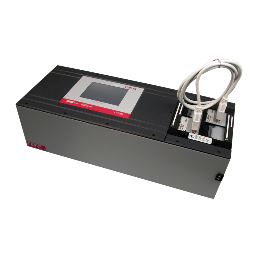
- Page 1 Touch 1 Getting Started Guide and User’s Reference Version 5.0D 10 Aug 2007...
- Page 2 Touch 1 Getting Started Guide and User’s Reference Version 5.0D Copyright© 2007 by Cirris Systems Corporation All Rights Reserved Cirris Systems Corporation 1991 W. Parkway Boulevard Salt Lake City, Utah 84119...
-
Page 3: Table Of Contents
Table of Contents Chapter 1: Setting up the Touch 1 ___________________________ 1 Check that you have all the required items ____________________ 1 Plug in your Touch 1 analyzer: ______________________________ 1 Setting up the Analyzer ____________________________________ 3 Installing Add-on Scanners _________________________________ 3... - Page 4 CON - Wire Connections (Net List) _________________________ 24 LABEL - Custom test point labels __________________________ 24 COMP - Components (resistors, diodes, capacitors, etc.) ________ 25 4-WIRE – Four Wire wirelists _____________________________ 25 SPC - Statistical Process Control ___________________________ 25 SCRIPT - Test Event and Custom Components _______________ 25 Chapter 6: Saving and Retrieving Wirelists and Scripts ________ 26 Saving a Wirelist ________________________________________ 26 Retrieving a Wirelist _____________________________________ 26...
-
Page 5: Chapter 1: Setting Up The Touch 1
Test Point Expansion boxes - adds 128 test points per box (1024 points maximum). A variety of Cirris Mating Adapters in many types, sizes, and quantities. Touch 1 Performance Check Kit consisting of three special adapters and a manual. A Network Card which is preinstalled by Cirris. - Page 6 Hipot Warning! Possible electric shock! Cirris hipot testers are designed to be safe for operators. Injuries from hipot test equipment are rare; however, not every hipot test situation is safe. Hipot testing is not dangerous to healthy individuals; although at times a mild electric shock may be experienced.
-
Page 7: Setting Up The Analyzer
Installing Add-on Scanners You can install up to 7 add-on scanners for a total of 1024 points in a system. On the Touch 1 main unit, remove the scanner cover plate by rotating the twist-lock fasteners 90 degrees so they go from vertical to horizontal. -
Page 8: Powering Up And Verifying The Software Is Running
Powering up and verifying the software is running Turn on the Touch 1 analyzer by pressing the power switch on the back of the analyzer. The power-up Self Test is automatic and will go away when it is finished. -
Page 9: Using The Help System
Chapter 1: Setting Up the Touch 1 The system This button is the Help Icon. Use it wherever it is begins at the available to get Help on nearly every aspect of your Main Menu Touch 1 analyzer. with the wirelist... - Page 10 Chapter 1: Setting Up the Touch 1 Using Context-sensitive Help You can get Help on any item you see in a window, whether it is text, a button, or a list. Text Scroll boxes Press the Help button once, then press the part of the window for which you want information.
-
Page 11: Installing Optional Software
Appendix D and Chapter 6 in this manual to enable and begin to use scripting. Using Cirris Adapters Connector adapters snap directly into the Touch 1 and mate to the device-under-test. You can mix or match the various kinds of adapters in combinations that work for you. -
Page 12: Chapter 2: Creating A Wire List (Learning)
To change an existing wirelist, see Chapter 5: Editing Wirelists. Learning uses a group of settings that you can adjust in order to meet your specifications. The Touch 1 will store your settings and use them for any subsequent learn. -
Page 13: Installing Adapters Before A Learn
Chapter 2: Creating a Wire List (Learning) Installing Adapters Before a Learn Adapters must be installed in the same "J" positions for testing as when the device was learned. If they are in a different order when you start a test, the analyzer will ask you to reposition them where they were in the original learn. -
Page 14: Changing Learn Settings
Chapter 2: Creating a Wire List (Learning) The analyzer will then learn the device. These Signatures are described in the Help Index under Signatures: Overview. Note: If a test program has components, the paramater signature is –MULTI. If a test program has advanced hipot settings or a voltage greater than 1000 V, the parameter signature is -00000. -
Page 15: Hv - High Voltage Parameters
Resistance setting. Before creating a wirelist by learning a sample, you can get the Touch 1 to find the resistance of all the wires of the sample. Calc Sample Cable allows you to establish a reasonable connection resistance parameter by comparing several sample devices. -
Page 16: Masking Test Points During High Voltage Testing
Point masking refers to removing from high voltage testing a selected set of test points. For details, see the Touch 1 Help Index under the Masking Points entry or look in Appendix D: Scripting under the Selectively Applying Hipot Voltage section. -
Page 17: 4-Wire Settings
4-wire fixture and then the device-under-test attached to the fixture. For more information, see Appendix B: Four-Wire, or download a copy of the four-wire application note from the Cirris website, or search the Help Index under Four-Wire Test - Overview. SPC Data Collection Settings Use MORE, SPC to turn data collection on or off for each specific wirelist and to choose what data you want collected. -
Page 18: Sample Wirelist Printout
Chapter 2: Creating a Wire List (Learning) To view a specific Use the CHANGE button to section of the wirelist, access the changeable use any of the items for the section that is buttons to highlight highlighted. that area. You can PRINT the You can use the arrows and wirelist for manual slider to view the sections of... - Page 19 Chapter 2: Creating a Wire List (Learning) TOUCH 1 CABLE DOCUMENTATION Filename: untitled.wir Date: 8/1/2003 Search the CRC Signature: 498EUS Help Index Cable Signature: 64B075 under Parameter Signature: 2J8NH Signatures - Cable Description: Last Learned Overview. Cable Serial Number: Adapter Signature(s): ....Adapter Descriptions(s): This is the 3BAF92 ......
-
Page 20: Chapter 3: Testing A Device
Before you begin a test session or ―run‖, the correct adapters must be installed in the correct ―J‖ position in the analyzer. If you press TEST without the correct adapters in the correct positions, the Touch 1 will prompt you with the necessary information to configure the adapters in the analyzer. -
Page 21: Chapter 4: Analyzing Test Errors
Chapter 4: Analyzing Test Errors There are many features on the Touch 1 to help you find and resolve errors. Probe the test points of the error Error tones can be used to with the hand-held probe. identify more common errors. - Page 22 Chapter 4: Analyzing Test Errors How test parameter settings define opens Wires Only Components Short A Short indicates either an unintended wire connections or improper settings of test parameters. Example: Explanation NET 1: NET <n> refers to a connection of two or more test SHORT J1-001 J1-015 TO points of which the test points listed in the error are J2-003 J2-004...
- Page 23 Chapter 4: Analyzing Test Errors High Resistance error High Resistance errors indicate detected resistance greater than what defines a good connection but less than what is either ignored or considered an open. Example: High Resistance Errors: NET 1: Measured 2.00 K ohm Detected at J1-001 J2-001 How test parameter settings define high resistance Intermittents...
-
Page 24: High Voltage Errors
NET 1: refers to a connection. Nets are numbered in J1-013 J1-053 the order listed under CON in the Editor and under Common Connections in the report Touch 1 Cable Dielectric Failure NET NC: Documentation J1-026 NET NC: refers to test points not in nets such as the... - Page 25 J1-001 J1-014 the order listed under CON in the Editor and under 4.34 M ohm Common Connections in the report Touch 1 Cable High Voltage Leakage NET NC: Documentation J1-026 NET NC: refers to test points not in nets such as the 5.68 M ohm...
- Page 26 NET 1: refers to a connection. Nets are numbered in J1-013 J1-053 the order listed under CON in the Editor and under Common Connections in the report Touch 1 Cable Overcurrent NET NC: Documentation J1-026 NET NC: refers to test points not in nets such as the unused pins of a connector.
-
Page 27: Chapter 5: Editing Wirelists
Chapter 5: Editing Wirelists Using the Wirelist Editor Purpose: View or print the wirelist (Touch 1 Cable Documentation) Add parts not learned such as components Change existing parameter settings Create wirelists from templates In the Main Menu press Test Setup. -
Page 28: Adp - Adapters
Chapter 1: Setting into the wirelist. Up the Touch 1 in the Using Cirris Adapters section. LV - Low Voltage (Continuity) Test For information on editing the Low Voltage parameters, refer to Chapter 2: Creating a Wirelist in the LV- Low Voltage Settings section or in the Help Index search for Low Voltage parameters. -
Page 29: Comp - Components (Resistors, Diodes, Capacitors, Etc.)
Chapter 5: Editing Wirelists If your labels end in a Labels can be loaded from number, the Touch 1 will try another file and applied to to increment the label for points in this wirelist. you. You can touch here to... -
Page 30: Chapter 6: Saving And Retrieving Wirelists And Scripts
Wirelists can be retrieved from floppy disk, the hard drive in the Touch 1 and from your network. Retrieving a wirelist replaces the Last Learned wirelist. The last retrieved wirelist will remain loaded even if power is interrupted. -
Page 31: Changing Cable Descriptions
Note: When a wirelist is retrieved, the Touch 1 will evaluate the wirelist and report any error in syntax as it is loaded. If there are no messages while retrieving a wirelist, the syntax of the wirelist is correct. -
Page 32: Chapter 7: Setting System Options And Test Controls
In the Main Menu press System Setup. Disk Utilities Disk Utilities allow you to copy and delete files as well as format floppy disks for use in your Touch 1 analyzer. Files may be copied or It is not possible to copy a wirelist to deleted singly or as a the same location as the original. -
Page 33: Digital Outputs
I / O connector. properly. Signature Display The Touch 1 uses a CRC signature. You can choose to display the ―old‖ style of signature from the Cirris 1000R+ / H+ series in addition to the new CRC signature. -
Page 34: Reports
Chapter 7: Setting System Options and Test Controls Reports Use the Help Button for more information. The Touch 1 analyzer can print the test status With the scripting option, you can automatically in several design custom reports that can be formats. - Page 35 Chapter 7: Setting System Options and Test Controls Selecting ALL or Set Up Security Each user can be allowed different levels will give access to the security of access by choosing system to that user. from the list. One user must be set up as an administrator with ALL security levels enabled.
-
Page 36: Date & Time
New versions of software as SPC Data Collection and can be installed using the Scripting. Install New Version option. Contact Cirris for a complete The process will prompt list of the available Optional you for the materials Features. needed to complete the... -
Page 37: Tester Checkout
Chapter 7: Setting System Options and Test Controls Tester Checkout Many facets of the Simply choose the test that you analyzer can be verified would like to perform and the by you in the work area. analyzer will do the rest. Utilizing a Performance Some of the tests require parts Check Kit and the Tester... -
Page 38: Language
Chapter 7: Setting System Options and Test Controls Language Different languages are available for your analyzer. Simply choose the language you require from the list and select CHANGE LANGUAGE. The language will change immediately. Setting Test Controls Test Controls such as Single Test / Continuous Test and Automatic / Manual Hipot are global, they are not stored as part of the wirelist. -
Page 39: Chapter 8: General Information
To verify calibration and functionality, you can purchase the Touch 1 Performance Check Kit. The Touch 1 Performance Check kit has a valid calibration period of 5 years after which it must be replaced. In addition to the performance check kit, you need a calibrated volt meter and high voltage probe capable of measuring the highest high voltage the tester is capable of outputting. -
Page 40: Conditions For Operation
Newer Touch 1 testers will automatically adjust to a line voltage of either 120V 60 Hz or 240ACV 50 Hz. If you use a Cirris product in a manner not specified in this manual and the accompanying help system, the... -
Page 41: Appendix A: Specifications
Appendix A: Specifications CAPACITY: 128 to 1024 points in 128-point increments TEST LEVELS: Low Voltage Tests: 5 volts @ 6mA max current High Voltage Tests: Standard: 50-1000VDC (in 1 volt steps) ±5% (50-707VAC ±5% optional) Option: 50-2000VDC (in 1 volt steps) ±5% (50-1000VAC ±5% optional) SENSITIVITY: Connection Resistance: 0.1 ohm to 100k ohm ±... - Page 42 Warranty Cirris Systems Corporation warrants the Touch 1 Cable Analyzer to be free of defects in materials and workmanship for a period of one (1) year from the date of delivery to you, as evidenced by receipt of your warranty registration form. In the event a defect develops due to normal use during the warranty period, Cirris Systems will repair or replace the analyzer with a new or reconditioned unit of equal value.
-
Page 43: Appendix B: Four-Wire "Kelvin" Testing
Appendix B: Four-wire “Kelvin” Testing What is 2-wire and 4-wire? If you've used an ohmmeter to make resistance measurements you've probably heard terms such as "2- wire measurement" and "4-wire Kelvin measurement." This document explains how ohmmeters measure resistance, how 2-wire resistance measurements work, how 4-wire resistance measurements work, and the special considerations for each measurement type. - Page 44 Cirris testers that measure resistance have this feature. Also, adapters that plug directly into Signature series testers eliminate much of the fixturing resistance that often occurs with adapting cables. If you need your resistance measurement to be accurate to only 0.1 ohms you won't need to use 4-wire on your Cirris tester.
- Page 45 4-wire will greatly improve accuracy. It allows you to measure lower resistance values than 2-wire testing. On Cirris hipot testers we use a higher current (up to 1Amp) when performing 4-wire Kelvin tests. This allows us to more accurately measure lower resistances, all the way down to 1 m...
- Page 46 Type2 point. The location of these T1 and T2 points on the adapter pins is determined by internal wiring. The Touch 1 can locate Type 1 and Type 2 pins automatically This is especially useful if the pattern is irregular.
- Page 47 Appendix B: Four-wire ―Kelvin‖ Testing There are two patterns for matching Type 1 and Type 2 points to 4-Wire pairs. Alternating - Net List and Hidden Points Alternate in the Same Adapter Advantage: Ease of use (ribbon cable) - solder adjacent wires to join 4-Wire Pairs. Disadvantage: ...
- Page 48 Appendix B: Four-wire ―Kelvin‖ Testing (KP) EFINITION ELVIN OINTS A Kelvin point is a place that makes a ―Y‖ junction by joining three parts: One of the end points of the 4-wire measurement. First wire of a 4-wire pair. ...
- Page 49 Appendix B: Four-wire ―Kelvin‖ Testing Method #1: Learn the fixture and sample to automatically detect 4-wire pairs and 4-Wire components. This is the easiest way. Method #2: Convert an existing 2-wire wirelist by hand-entering 4-wire pairs and adding 4-Wire components. Method #1: Learning a Fixture &...
- Page 50 Appendix B: Four-wire ―Kelvin‖ Testing In the Main Menu, press Test Setup. In Test Setup, press Retrieve Wirelist. In Retrieve Wirelist, select the desired wirelist, then press Retrieve. In Test Setup, press View & Change Wirelist. Optional: If you are converting a 2-wire wirelist to 4-wire by adding fixture wires to a new adapter, add the adapter to the wirelist.
- Page 51 Appendix B: Four-wire ―Kelvin‖ Testing ELECT THE IDDEN OINT 1. In Four-Wire Pair, press Hidden Point. 2. In Add/Change Four-Wire Point, select the hidden test point of the same 4-wire pair for which you just selected the net list point. Why are not all test points available for the hidden point? Each 4-wire pair requires one T1 and one T2 point.
- Page 52 Appendix B: Four-wire ―Kelvin‖ Testing 4-W R ESISTOR Sets the resistance value and tolerance for resistors or wire segments between : 0.001 to 1.0M 4% 0.001 two Kelvin Points (KP). R ANGE : 1-99% OLERANCE A 4-Wire Component is required for each 4-wire measurement. Important! ...
- Page 53 Appendix B: Four-wire ―Kelvin‖ Testing – F – & T NTER THE OCATION OF THE EASUREMENT 1. In Add/Change 4-Wire Wire [or] Resistor, press the From box. 2. In Add/Change Component, select (highlight) a test point using: Up/down arrows Scroll bar (gray between arrows) Hand-held probe. Then press OK.
- Page 54 Appendix B: Four-wire ―Kelvin‖ Testing Relationship of LV Continuity Settings to 4-Wire Component Values Connection Resistance should be Component Resistance should be at least 20% higher than the at least 20% lower than the resistance value of any 4-Wire resistance value of any 4-Wire Components used in this region.
- Page 55 Appendix B: Four-wire ―Kelvin‖ Testing Troubleshooting: Learning 4-Wire Fixture Errors RROR ESSAGE Invalid 4-Wire Kelvin Pair: More than two points connected J1-001 J1-002 J3-063 J3-064 Possible Causes: Solutions: 1. Do one of the following: The sample cable was not removed before ...
- Page 56 Appendix B: Four-wire ―Kelvin‖ Testing Possible Causes: Solutions: Raise Connection Resistance so Setup Error: Connection Resistance is set lower it is 20% higher than the 4-Wire Component than the detected resistance of a good value describing the connection causing the connection.
- Page 57 Appendix B: Four-wire ―Kelvin‖ Testing RROR ESSAGE Bad 4-W Resistor between: J1-001 and J3-063 [also: Resistor Missing] Expected value 1.00 ohm 1% Measured value: 1.30 ohm Possible Causes: Solutions: Setup Errors: Incorrect or unrealistic settings: Edit the 4-Wire Resistor reporting the error. Component Value or Tolerance.
- Page 58 Appendix B: Four-wire ―Kelvin‖ Testing Test Point Identification – Fixture Adapters vs. Device Under Test IXTURE IXTURE = Plug, pin 1 <= connected => Socket, pin 1 = J3-063 J1-001 = Plug, pin 2 <= connected => Socket, pin 2 = J3-061 J1-003 IST USING EFAULT...
-
Page 59: Appendix C: Spc Data Collection
4. Retrieve SPC Data for future analysis. 5. Analyze SPC Data. Activate SPC Data Collection on your Analyzer Note: SPC Data Collection is sold as an option on the Touch 1. From the Main Menu, select System Setup. From the Setup Menu, select Software Update. - Page 60 Appendix C: SPC Data Collection The File Location shows where the SPC Data Collection files are being stored. This can only be Once a data file has been changed if the tester is created, you can verify the connected to a network. integrity of the file, copy the file, or delete the file.
- Page 61 Appendix C: SPC Data Collection The wirelist will then reflect the changed SPC Data Collection options. Storing SPC Data SPC Data is stored in a temporary archive as each test is performed on the analyzer. The SPC Data is stored in the File Location when the run is complete, indicated by returning to the Main Menu. Do NOT remove the floppy disk until the drive light goes off.
- Page 62 Retrieving and Analyzing SPC Data Cirris SPC Data can be read and stored by SPCLink, software that comes with your SPC Data Collection package. Your data can then be exported in a delimited format for use with spreadsheet or data analysis software packages.
-
Page 63: Appendix D: Scripting
Appendix D: Scripting Scripting is sold as an option on the Touch 1. Activate Scripting on your Analyzer Scripting allows you to implement a wide variety of custom functionality to your analyzer. Think of Scripting as having a multi-point Volt ohmmeter where you can specify what measurements you want to make, where to put the leads, and what to do with the results, all controlled automatically. - Page 64 Appendix D: Scripting The Scripting option is now available on your analyzer. Attach a Script to a Wirelist Each wirelist can utilize scripts differently. Therefore, Scripting must be defined for each wirelist independently. Modify a current wirelist by selecting View & Select More, then SCRIPT.
- Page 65 Zener diode tests to the wirelist, each with its own set of parameters. More information on Scripting can be found in the Help System under Scripting – Overview. Cirris can write your Custom Component for you. Call us at 1-800-441-9910 for a quote. Event Scripts (.evt ) An event script differs from a custom component in that there is only one event script for each wirelist.
-
Page 66: Appendix E: Parent / Child Wirelists
Appendix E: Parent / Child Wirelists What are Parent / Child Wirelists? Parent / Child Wirelists are separate tests that are strung together so that all of the individual tests run but only one final result is returned at the end of all of the tests, either Pass or Fail. The Parent test is the starting point or entry into a set of tests. - Page 67 Appendix E: Parent / Child Wirelists In Change Learn Components select Child Wirelist(s). Now select OK. You will return to the View/Change Learn Settings screen. Select OK again. You will now return to the Learn Setup screen. Select LEARN. In Child Wirelist Learn select LEARN In Name Multiple Wirelists fill in the boxes Child 1.
- Page 68 Appendix E: Parent / Child Wirelists After learning, in the Child Wirelist In Child Wirelist Learn, either LEARN the Overview, select SAVE. next Child or select DONE. You can discard the learn and try again if the results were not as expected.
-
Page 69: Appendix F: Digital I/O
Appendix F: Digital I/O What is Digital I/O? The Touch 1 can send and receive triggered events through the 15 pin Digital I/O port on the back of the analyzer. External devices like stampers, markers, and locking devices can be activated and deactivated as necessary to enhance your testing requirements. - Page 70 Appendix F: Digital I/O Setting up Digital I/O The two defined inputs, External Switch and Hipot Safety Switch, are enabled in the Test Controls area. See Chapter 7: Setting Test Controls for more information. User Defined Inputs are accessed through Scripting.
- Page 71 Select trigger events for the RISING and FALLING positions. FALLING events turn a device on and RISING events turn a device off. Both events must be defined and they must be different events. The following schematics are examples of how to connect external devices to the Touch 1 using the Digital I/O function.
- Page 72 Index diodes errors, testing, 18 learning, 12 AC High Voltage. See Help Index: AC Hipot Test range of learning and testing, 8 AC voltage option verifying installation of, 4 Adapter Descriptions displayed error tones. See Help Index: Error Tones in reports, 14 errors Adapter Signatures reports, setting up, 27...
- Page 73 Index range of learning and testing, 8 retrieving Intermittent Error, 18 wirelists, 25 Reversed diode [error], 18 lamps driving, external, 27 Scripting Leaky diode [error], 18 unlocking, 27 learning, wirelists, 8 Scripting Option, 7 LEDs scripts driving, external, 27 deleting, 27 range of learning and testing, 8 SCSI terminators testing, 8...
- Page 74 Index Which-End detection, 33 wirelists copying, 27 deleting, 27 editing, 22 learning, 8 moving, 27 printing, 13 re-naming, 27 retrieving, 25 wires range of learning and testing, 8 resistance, finding, 11...
Need help?
Do you have a question about the Touch 1 and is the answer not in the manual?
Questions and answers