Cirris CH2 xHVC User Manual
Hide thumbs
Also See for CH2 xHVC:
- User manual (64 pages) ,
- Instruction manual (41 pages) ,
- Performance test manual (21 pages)
Table of Contents
Advertisement
Quick Links
Advertisement
Table of Contents

Subscribe to Our Youtube Channel
Related Manuals for Cirris CH2 xHVC


Summary of Contents for Cirris CH2 xHVC
- Page 1 Cirris CH2 xHVC User Manual...
-
Page 3: Table Of Contents
5. System Set Up ......18 5.1 Setting up the CH2 xHVC Base Unit ..18 5.2 Installing Optional Expansion Scanners . -
Page 4: Safety
Operators must not touch the device under test, the test fixture / test cables or the output terminals of the Chroma Power Supply or the CH2 xHVC test points during high voltage testing. Doing so can result in serious injury or death. -
Page 5: Test Station Safety Overview
• Explosive Environment - Do not operate the test system in the presence of flammable gases or fumes. • Safety Interlock - A safety interlock MUST be used with the CH2 xHVC system. If using dual safety palm switches, they should be permanently fixed at least 22” apart. - Page 6 E-Stop in the event of an emergency. • Require Safety Switch Cycling - Cirris STRONGLY recommends setting the Easy-Wire software to check that safety switches are cycled from a closed condition during a high voltage test to an open condition between tests.
-
Page 7: Test System Symbols
Test System Symbols DANGER - High Voltage The lightning bolt symbols on the front of the CH2 xHVC Base Unit and on the front and rear of the Chroma Power Supply inform operators that high voltage may be present and to take proper safety precautions to avoid the risk of injury or death. -
Page 8: Safety Interlocks
CH2 xHVC system are wired to meet this condition on both units simultaneously. The high voltage safety interlock on the CH2 xHVC Base Unit is satisfied by closing the connection between pins 6 and 25 in the Digital I/O connector on the back panel of the unit. -
Page 9: Wiring Safety Interlocks
Wiring Safety Interlocks The basic Palm Safety Switches generally supplied with the CH2 xHVC system are wired as shown in the schematic below. The palm switches are normally-open, double-contact devices. The switches close when the buttons are depressed and open when the buttons are released. The system will only start a hipot test if both palm switches are depressed. -
Page 10: Introduction
CH2 test systems can perform Dielectric Withstand (DW) testing at up to 1500 VDC or up to 1000 VRMS while CH2 xHVC systems can perform DW testing at higher voltages - up to 2120 VDC or up to 1500 VRMS (the maximum IR voltage remains 1500 VDC). -
Page 11: The Chroma Power Supply
The Chroma Power Supply The CH2 xHVC is designed to act as a single system. The Chroma Guardian Series 19052 Power Supply has been integrated as a component of the system and as such it will not be necessary for programmers or operators to interact directly with the Chroma 19052 except to turn the unit on and off. -
Page 12: Service
Conditions of Operation The CH2 xHVC test system is intended to be used indoors at a temperature of 50 to 104 degrees Fahrenheit (10 to 40 degrees Celsius). Best performance can be obtained at a relative humidity less than 70%. Insulation Resistance Measurements will degrade at over 70% relative humidity. - Page 13 Introduction...
-
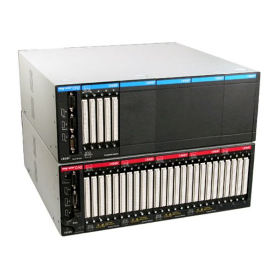
Page 14: System Hardware
3. System Hardware The items supplied in the CH2 xHVC shipment would have included: ● CH2 xHVC Base Unit ● Chroma 19052 Guardian Power Supply Unit ● Hand-Held Probe CH2 XHVC Base Unit (with 800 test points) ● USB Cable ●... - Page 15 Also required with the system is a safety interlock. ● Palm Safety Switches with Emergency Stop Switch. Note: If not using the basic Palm Safety Switch set supplied by Cirris, a suitable safety interlock must be used instead. Palm Safety and...
-
Page 16: Software Installation
The installation for the latest version of the Easy-Wire Station software would have been included on a USB flash drive with the shipment of a new CH2 xHVC system. To be compatible with the xHVC system, the test station PC controller must be running Easy-Wire version 2020.1.0 or later. -
Page 17: Installing The National Instruments Drivers
Install the National Instruments Drivers The CH2 xHVC uses a GPIB interface to communicate between the Easy-Wire software and the Chroma Power Supply. The supplied National Instruments GPIB-USB-HS+ device will be used for this purpose. The installation for the NI-488.2 software drivers needed to support the device can be found on the USB flash drive supplied with the test system. -
Page 18: System Set Up
5. System Set Up As part of setting up a safe CH2 xHVC test station, the test system should be separated from the normal work flow as noted in the Safety Section at the beginning of this manual. For improved performance it should also be placed at least 2 feet (60cm) from electrical noise emitting devices such as florescent lights and electric motors. -
Page 19: Installing Optional Expansion Scanners
Base Unit and Expansion Enclosures support this system configuration. Racking: The CH2 XHVC Base Unit, the Chroma Power Supply and the Expansion Scanner Enclosures are all designed to accommodate racking in standard 19” electronics cabinets as an alternative to direct stacking. -
Page 20: Connecting The Xhvc Power Supply
It’s important to note that the function buttons on the Chroma Power Supply are locked at the factory. Communication with the unit in the CH2 xHVC system is handled exclusively through the Easy-Wire software and in typical usage it will not be necessary to interact directly with the Chroma Power Supply. However, should it become necessary to access the unit’s function keys for configuration purposes or when sending the unit for calibration, the password to... - Page 21 5. Connect the Palm Safety Switches by attaching its 25-position D-Sub connector to the Digital I/O connector on the back panel of the CH2 xHVC Base Unit. Connect the ends of the two stripped wires to the two Interlock terminals on the 11-position, vertical terminal strip on the back panel of the Chroma Power Supply. Either of the stripped wires can be connected to either of the two Chroma Interlock terminals.
-
Page 22: Connecting Power To The System
The Chroma Power Supply primary (mains) power input selector switches should have been set in Step 1 above. The CH2 xHVC Base Unit and Expansion Scanners will automatically adjust to AC input from 100 - 240 volts AC, 50-60 Hz. -
Page 23: Initial Start Up
Initial Start Up Power on the Chroma Power Supply and the CH2 xHVC Base Unit. The power switch for the CH2 xHVC Base Unit is on the rear of the enclosure next to the AC Input receptacle. The power button for the Chroma Power Supply is on the bottom left of the unit’s front panel. - Page 24 If the Easy-Wire software successfully initializes the CH2 xHVC Base Unit and the system passes self- test the software will open and show Ready on the Main Menu.
- Page 25 External (Chroma) Supply failed to respond. Following are a few troubleshooting steps to try if this occurs the first time starting up the system. Cirris Technical Support is also available to provide assistance: ● Check the GPIB interface device to ensure it’s connected securely on both ends.
-
Page 26: Troubleshooting A Red Status Indicator
2. Verify that the USB cable is connected between the computer and the Base Scanner. 3. Reboot the tester. If the problem persists, write down the error messages that appear after launching the software, and call Cirris for assistance. CH2 xHVC User Manual... -
Page 27: Checking The Sound
Checking the Sound The Easy-Wire software relies on sound prompts to provide test feedback to the operator. In the Easy-Wire Main Menu, click the Test Sound button. You should hear two trumpet sounds coming from the tester. 2. If you hear the sounds, skip to “Connecting to a Network” on page 14. - Page 28 5. Open the “Computer” tab and click Change Volume. 6. Adjust the volume slider and click Test to try out the setting. When the volume is at the desired level, click Done. 8. The “Setup System Options” window will be open. Click CH2 xHVC User Manual...
- Page 29 ● Verify that the speakers are on and that the volume is turned up. ● Verify that the volume on your PC is turned up (the PC volume control can be found on your Windows task bar). If the sound problem persists, call Cirris for assistance. System Set Up...
-
Page 30: Test Fixtures / Test Cables
Test (DUT). Various approaches can be used, but the general concept is straightforward - test cables/fixtures connect the tester’s test points to the DUT’s termination points. Cirris divides the test hardware into two catego- ries - Smart fixtures and Traditional fixtures. However, before getting into the details, it’s helpful to understand a bit about the process of creating test programs in the Easy-Wire software. - Page 31 Optional Connector Savers Sacrificial Connector Savers protect the pins in the CH2 xHVC tester from wear and damage. Each saver covers one scanner module (160 points). Connector Savers include injector/ejectors that allow for quick connect and disconnect of mating cables.
- Page 32 As both layout views are the same, it makes it straightforward to use the probe method to attach connectors as the software will present the graphic and instruct the operator to probe the highlighted connector position. The probing is performed on the DUT mating connector with the test cable connected to the tester. CH2 xHVC User Manual...
- Page 33 Fast Attach can only be used with 2-wire fixtures and each DUT mating connector of a Fast Attach type must be wired in the same sequence to the CH2 xHVC test points. The pattern doesn’t necessarily have to be sequential, as shown in the example below, and it doesn’t have to be to wired to the same tester mating connector.
- Page 34 Capacitance measurements are used in the process. Therefore, the feature is much more accurate if wires in test cables/fixtures on either side of a connection are the same length and preferably as short as possible. CH2 xHVC User Manual...
-
Page 35: 4-Wire Fixtures
4-Wire Fixtures The 4-wire (Kelvin) measurement method allows the CH2 xHVC system to measure resistances as low as .001 ohm and if the test fixture is properly configured, it can eliminate the resistance of test cables/fixtures from the mea- surement. However, 4-wire measurements require special test cables/fixtures with each side of the measurement requiring two test points (four points total for each measurement). - Page 36 Each test point has a specific mate that ● Hidden Point can be used in a 4-wire pair. The pattern on the CH2 xHVC is very straightforward as the 4-wire mate for each point is hori- Visible Point zontally opposed in the tester’s interface connectors.
- Page 37 Test Fixtures / Test Cables...
-
Page 38: Operation
● Standard CH2 test systems can perform Dielectric Withstand (DW) testing at up to 1500 VDC or up to 1000 VRMS and Insulation Resistance (IR) testing at up to 1500 VDC. The Easy-Wire CH2 xHVC system can perform DW testing at higher voltages - up to 2120 VDC or up to 1500 VRMS. While the Chroma Power Supply can be used to provide the higher voltages for the DW testing, the CH2 internal DC power supply is always used for IR testing and the maximum IR voltage remains at 1500 VDC. -
Page 39: Testing
The Total Current is normally set higher to account for the capacitive current. See the Cirris Web Site for more information on the subject of Total Current and Real Current in AC hipot testing. - Page 40 Wire software will display a message instructing the operator to Engage HV Safety Switch to start high volt- age testing. The tester will wait at this stage until the high voltage safety interlock is engaged before it begins high voltage testing. CH2 xHVC User Manual...
- Page 41 5. If the high voltage safety interlock opens at any time during high voltage testing, or the Emergency Stop button is pushed, the high voltage output will be turned off, all test points will be connected to ground to discharge the Device Under Test (DUT) and the test will be aborted in a Failure condition.
-
Page 42: Adding Or Removing Scanner Modules
The process for doing so is described below. Some of the photographs in this section are taken of a standard CH2 system. The hardware in the a CH2 xHVC is very similar and the for all practical purposes the process of adding and/or removing scanners will be identical on the two systems. - Page 43 3. Lift the scanner and node modules partially out of the chassis to expose the wiring. 4. Unplug all of the connectors from the Node/Scanner 5. Remove the Node/Scanner assembly. Set this assembly so the Node Module is facing down. Adding or Removing Scanner Modules...
-
Page 44: Separating Scanner Modules
2. While holding the scanner to be removed with one hand, press the retaining latch INWARD. 3. Insert a flat blade screw driver in the slot next to the retaining latch. Twist the screw driver to slightly separate the scanner. CH2 xHVC User Manual... -
Page 45: Adding A Scanner Modules
4. Repeat steps 2 and 3 on the other three latches. 5. Lift the assembly straight up to remove it. Adding a Scanner Align each tab on a Scanner Module with the corresponding slots in the previous module. Adding or Removing Scanner Modules... -
Page 46: Reassembling The Unit
Align the Scanner/Node assembly with the mounting pins in the chassis. 2. Attach all of the power cables to each of the modules 3. Make sure the TERMINATOR is in place on the last scanner in the stack. CH2 xHVC User Manual... - Page 47 4. Route the base control cable through the notch in the casework. Adding or Removing Scanner Modules...
-
Page 48: Accessing Easy-Wire Help
9. Accessing Easy-Wire Help In addition to this CH2 xHVC User Manual and the Easy-Wire Software Manual for CH2 & CR Testers, the Easy-Wire Help is also a valuable reference resource which can be accessed from any location within the software. - Page 49 To search the Help system by keywords, select the Magnifying Glass icon. Accessing Easy-Wire Help...
-
Page 50: Help / Support
In the United States, contact our technical support team: 800-441-9910, ext. 666 (or ask for Tech Support) • Outside the United States, call +1-801-973-4600 or visit www.cirris.com to find the Cirris office nearest to you. • Visit www.cirris.com/learning-center to read articles on Cirris products and other testing subjects. -
Page 51: Specifications
11. Specifications Test Points Max Points Per Net 160 to 800 points; expandable to 100,000 points in Unlimited 160-point increments. (Max distance from base unit: 200 Digital Input/Output ft.) 8 Inputs / 8 Outputs, 30 V Open collector, +12 V and +5 V Low Voltage Test each, current limited to 100 mA ■... - Page 52 CH2 xHVC User Manual Version 2020.1.0 © 2020 Cirris Systems Corporation 401 North 5600 West Salt Lake City, Utah 84116 U.S.A. www.cirris.com...
Need help?
Do you have a question about the CH2 xHVC and is the answer not in the manual?
Questions and answers