
Subscribe to Our Youtube Channel
Related Manuals for Steca TR A503 TTR U


Summary of Contents for Steca TR A503 TTR U
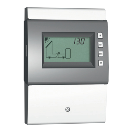
- Page 1 Temperature differential controller with integrated data logger 5 inputs, 3 outputs Installation and operating instructions 742.118 | Z03 | 14.50 | Subject to change due to technical improvements!
-
Page 2: Table Of Contents
Contents 1. General safety instructions ..............3 2. Proper usage ..................4 3. About these instructions ...............4 Contents ......................4 Target audience ..................... 4 Danger levels in warning notices Évaluation du niveau de risque dans les avertissements........4 4. Installation .....................5 Opening / Closing the casing ................. 5 Mounting the casing .................. -
Page 3: General Safety Instructions
13. Dismantling and disposal ..............52 14. Info messages ..................52 15. Troubleshooting ...................53 15.1 General faults ....................53 15.2 Error messages .................... 55 15.3 Checking the Pt1000 temperature sensor ............ 56 16. Technical data ..................57 16.1 Controller ....................57 16.2 Cable specifications ..................58 17. -
Page 4: Proper Usage
Proper usage The temperature differential controller, subsequently referred to as the controller, is an independently installed electronic temperature controller for on-surface installation. Integration into a pump assembly is possible when the technical specifications of the controller are adhered to. The maintenance-free controller is exclusively intended for controlling solar energy and heating systems. -
Page 5: Installation
Installation Note The following section describes only the installation of the controller. Follow the instruc- tions of each respective manufacturer when installing external components (collectors, pumps, storage tanks, valves, etc.). Opening / Closing the casing 4.1.1 Removing the front panel ... -
Page 6: Mounting The Casing
Mounting the casing √ The mounting location must satisfy the prescribed conditions of use; more informa- tion on this is provided in Section 16, p. 57. √ The mounting surface is vertical and allows good access for installation. Danger Risk of death by electrocution! • Disconnect the controller from the power supply before opening the casing. -
Page 7: Establishing The Electrical Connections
Establishing the electrical connections Danger Risk of death by electrocution! Make sure that the following conditions are satisfied when performing the work described in this section: • All cables leading to the controller must be disconnected from the power supply and it must be ensured that they cannot be unintentionally reconnected during installa- tion. - Page 8 4.3.1 Position of the terminals 0-10 R2 R3 R1 R2 1 2 3 4 5 const. const. PE PE PE PE Fig. 3: Terminals in the lower part of the controller (terminal cover removed) Power connection terminal block: 1x phase conductor (mains input) 2x output (TRIAC, for pumps or valves) R1, R2 1x output (relay, for pumps or valves)
- Page 9 4.3.2 Preparing the cable openings The cables can be fed through openings in the rear wall of the casing or at the bottom of the casing. The openings are pre-punched and must be prepared as required before installation. Prepare the cable openings in the rear wall of the casing as follows: ...
- Page 10 4.3.4 Inserting / Removing plastic links Insert the plastic links as follows: 1. Insert the right plastic link with the latching protrusion first (Fig. 4). 2. Press the other side of the plastic link down , until the spring clamp latches into place.
-
Page 11: Terminal Pin Assignments
Terminal pin assignments For each solar energy system that can be selected at the controller, the external compo- nents (pumps, valves, temperature sensors) must be connected to particular terminals. The following table provides information on • the graphic and number of the solar energy system on the controller display (the graphic is only intended to provide an overview and is not a technical drawing) and • the terminal pin assignments of the connected components. - Page 12 Display Legend Terminal layout 1 storage tank, 2 collector arrays T1: collector array 1 sensor T2: collector array 2 sensor T3: lower storage tank sensor R1: solar circuit pump, collector array 1 R1, N, PE (0–10 R1, R2: solar circuit pump, collector array 2 R2, N, PE (0–10 R2, 2 storage tanks, 1 collector array (pump-controlled) T1: collector array sensor...
- Page 13 Display Legend Terminal layout 1 storage tank, 1 swimming pool, 1 collector array (pump-/valve-controlled) T1: collector array sensor T2: lower storage tank sensor T3: swimming pool sensor R1: solar circuit pump R1, N, PE (0–10 R1, R2: storage tank switching valve R2, N, PE 1 storage tank, 1 collector array T1: collector array sensor...
- Page 14 Display Legend Terminal layout 1 swimming pool, 1 collector array T1: collector array sensor T2: swimming pool sensor R3: solar circuit pump R3, N, PE 1 swimming pool with external heat exchanger, 1 collector array T1: collector array sensor T2: swimming pool sensor T3: external heat exchanger sensor R3: solar circuit pump R3, N, PE...
-
Page 15: Commissioning The Device For The First Time
Commissioning the device for the first time Danger Risk of death by electrocution! Be sure to perform all the measures listed in Section 4 before starting the first commissioning. Notes • After commissioning the controller for the first time, it is configured in such a man- ner that it can be used in most applications without changes. - Page 16 Selecting a system 9. Press . System 1.1 is displayed, 1.1 flashes (Fig. left). 10. Press to select a different system. 11. Press SET. If in step 10 System 0.1 was selected then proceed with step 23. Setting pump 1 (output R1) 12.
- Page 17 23. Press . F: is displayed. Set the functions (necessary for System 0.1, or as required for other systems; The func- tions can also be set at a later date.) 24. Press SET to set the functions. F:01 (function num- ber) flashes (example in Fig.
- Page 18 Characteristics of high-efficiency pumps Display Pump type Characteristic curve High-efficiency pump with a 0–10 V 0 V: Pump off profile for a rising characteristic curve 10 V: Max. pump speed (Fig. 6) High-efficiency pump with a 0–10 V 0 V: Max. pump speed profile for a falling characteristic curve 10 V: Pump off (Fig.
-
Page 19: Structure
Structure Casing No. Element Section button (under Mode front panel) Slot for Micro-SD card (un- der front panel) Operating buttons , SET, ESC, Display Front panel Terminal cover 4.3.1 Terminal cover fastening – ... - Page 20 6.2.2 System graphics symbols The following tables describe the symbols used in the system graphics ( in Fig. 8). General Symbol Description Symbol Description Pipework Pump, switched on Collector (array) Pump, switched off Maximum collector tempera- 3-way valve with flow direction ture reached Storage tank Domestic water outlet...
- Page 21 6.2.4 Pictograms for functions The following table describes the pictograms used for functions ( in Fig. 8). Symbol Description Symbol Description Holiday – recooling Manual operation Pump is speed controlled Alarm output Interval Stagnation reduction Freeze recirculation Micro-SD card detected; data is recorded every minute.
-
Page 22: Operation
Operation This section contains general information on operating the controller. Operating buttons The device is operated using the , , SET, ESC and buttons as follows: • Scrolls up through the menu/initial commissioning • Increases the setting value by 1 step • Scrolls down through the menu/initial commissioning ... -
Page 23: Off" Mode
"Off" mode Functionality • All outputs are switched off (outputs/control outputs without power, relays open). • OFF and the software version are displayed alternately. See example in Fig. below: software version St 1.3. • Backlighting is red. • Settings menu can be called up. • The Off mode is preset when the device is delivered. -
Page 24: Automatic" Mode
"Automatic" mode Functionality Automatic is the normal mode of operation and the system is automatically controlled. The following actions are possible: • Display status (status display): display the status of external components (tempera- tures, switching states, run times). • Display stored min./max. values (temperature sensors) or sum/difference values (op- erating hours of the pumps and valves). -
Page 25: Settings Menu
Operation √ The controller shows the status display. You can display the status of external components as follows: Press to display the status of other components ( , shown using system 1.1 as an example). You can display and reset the stored min./max./difference values as follows: 1. - Page 26 Time/date System Functions Set time/date No system – 0.1 Drainback – F01 1 storage tank, Circulation – F02 1 collector array – 1.1 1 storage tank with heating return increase, Back-up heating – F03 1 collector array – 1.2 1 storage tank with external heat exchanger, Solid fuel boiler –...
- Page 27 Priority Factory setting Parameters SET for 5 seconds Storage tank 1 before Reset to factory Maximum temperature storage tank 1 – P01 storage tank 2 settings Storage tank 2 before Maximum temperature storage tank 2 – P02 storage tank 1 Maximum temperature swimming pool –...
-
Page 28: Calling Up The Settings Menu And Selecting A Menu Entry
Calling up the settings menu and selecting a menu entry √ Automatic or Off mode is selected. 1. Press and hold SET for two seconds. The settings menu is displayed, menu entry flashes. 2. Press to select a different menu entry. 3. -
Page 29: Setting The Priority
Setting the priority Functionality The priority determines the sequence in which the storage tanks are loaded (only for systems with more than 1 storage tank). If the higher priority storage tank (first-priority storage tank) cannot be loaded because the collector temperature is too low, then the lower priority storage tank (second-priority storage tank) is loaded . -
Page 30: Functions
Functions 10.1 Operation Displaying the functions The following information is visible when the functions are displayed: • Function number, e.g. F:02 (Fig. left) • Switching state: on: function is activated off: function is deactivated (Fig. left) Note If neither on nor off are displayed, then the function cannot be used. -
Page 31: Characteristics
Setting the characteristics The functions have different numbers of characteristics. The characteristic values are always set via the same sequence of operating steps. You set the values of characteristics as follows: √ The function has been activated as described previously. 1. - Page 32 Switch-on temperature difference If a function contains a differential thermostat, then the switch- on temperature difference can be set. The relevant sensor symbols flash. Switch-off temperature difference If a function contains a differential thermostat, then the switch- off temperature difference can be set. The relevant sensor symbols flash.
-
Page 33: Functional Description
Starting time of a time window When setting the start time of a time window, the following is displayed to the left of the start time (see Fig. left): • • Number of time window 1 ... 3, whose start time is to be set (in this case: 1) • on End time of a time window... - Page 34 10.3.1 Drainback Notice Danger of malfunction in drainback systems • In drainback systems, the drainback function must be activated. • In drainback systems with speed-controlled solar circuit pumps (sys- tems 1.1 to 4.2), note the following: – Activation of the drainback function switches off the speed control of the solar circuit pump, but this can be subsequently switched on again if desired (P:18/P:19 in Section 11).
- Page 35 Factory Display Characteristic min. max. setting Activation on, oFF Filling time 1 ... 10 minutes 3 minutes Stabilising time 1 ... 15 minutes 2 minutes Draining time: 1 ... 30 minutes 5 minutes Short startup time 0 ... 60 seconds 0 seconds Booster pump on, oFF...
- Page 36 Factory Display Characteristic min. max. setting Activation on, oFF Output (circulation pump) free output R1/R2/R3/R – Pump type (R1, R2 only) AC, HE Pump characteristic (HE only) bA, bb, C (see p. 18) – Temperature control on, oFF Sensor input for circulation 1 ...
- Page 37 10.3.4 Solid fuel boiler Controls a pump in order to heat a storage tank using a solid fuel boiler. The pump is switched on when all of the following conditions are satis- fied at the same time: • The temperature difference between the solid fuel boiler and the storage tank exceeds diff on • The solid fuel boiler temperature lies above the min.
- Page 38 Min. solid fuel boiler temperature 85 °F 200 °F 125 °F Control target for solid fuel boiler 32 °F 200 °F 140 °F temperature (Speed control = on) Notice Standard pump: Set AC! High-efficiency pump: Set HE! Notice External consumer (e.g. 115 V relay): Set AC pump type and set the speed control to oFF! 10.3.5 Quick charge Uses a higher loading temperature to load the upper region of the storage...
- Page 39 10.3.6 Heat quantity Calculates the acquired heat volume based on the following information: • Supply temperature • Return temperature • Flow rate determined using the following methods: – Calculated via pump speed – Measured using a pulse water meter (terminal 5) –...
- Page 40 Type 3: Grundfos Direct automatical- Sensors type ly detected 1-12, 1-20, 2-40, 5-100, 10-200, 20-400 Glycol proportion Supply sensor input (warm) 1 ... 5, E.1, E.2 – Return sensor input (cold) 1 ... 5, E.1, E.2 – display on, oFF /kWh 0.100 2.500...
- Page 41 10.3.7 Thermostat Switches an output on and off, depending on the temperature range of any desired sensor. The function can be time restricted and is set for heating or cooling as follows: Heating: The T value is set lower than T When the sensor temperature drops below T , the output is switched on until the temperature exceeds T...
- Page 42 Factory Display Characteristic min. max. setting Activation on, oFF Output free output R1/R2/R3/R – Pump type (R1, R2 only) 1) 2) AC, HE Pump characteristic (HE only) bA, bb, C (see p. 18) – Speed control (R1, R2 only) on, oFF Minimum speed (AC only) 100% Minimum speed (HE + bA only)
- Page 43 10.3.9 Interval Periodically switches the solar circuit pump on and off in order to meas- ure the actual collector temperature. The delay between 2 switch-on operations and the switch-on duration can be set. Applications: • Collector types where the mechanical construction prevents the temperature from being measured at a suitable place • Unsuitable position of the temperature sensor on the collector The function can be time restricted to prevent unnecessary periodic...
- Page 44 10.3.11 Holiday – recooling Attempts to reduce, or even to avoid, the system standstill (stagnation) times at high temperatures. To do this, at night the storage tank – or the second-priority storage tank if 2 storage tanks are present – is charged as far as possible to the set minimum temperature, if the storage tank temperature during the day was 20 F below the set maximum tempera- ture.
- Page 45 10.3.13 Freeze recirculation Attempts to prevent freezing of the collectors by pumping heat from the first-priority storage tank into the collectors: • The collector temperature is below 40 °F: solar circuit pump is switched on. • The collector temperature is above 45 °F: solar circuit pump is switched off. The freeze recirculation function is only useful when the heat transfer fluid contains insufficient or no anti-freeze.
- Page 46 Factory Display Characteristic min. max. setting Activation on, oFF Output free output R1/R2/R3/Rs – Control norm norm, InV More information is provided in Section 15.2, p. 55. norm = normal: contact closes when a fault occurs. InV = inverted: contact opens when a fault occurs. 10.3.16 System pressure monitoring If the system pressure exceeds the permitted range for more than 10 sec- onds, the system pressure monitoring indicates this by showing the...
-
Page 47: Parameters
Parameters Note the following when setting parameters: • Observe the operating data of the solar components used. • The individual parameters are only displayed and can be changed when this is per- mitted by the type of solar energy system that has been set. Special case: system 0.1 has no parameters;... - Page 48 Display Parameter min. max. Functionality Maximum collector + 40 F 350 °F 270 °F When the maximum collector temperature temperature is exceeded, no more loading occurs until the temperature drops to 6 F below the set value. Minimum collector 32 °F –...
- Page 49 Display Parameter min. max. Functionality Pump type R1 AC, HE Notice Pump characteris- bA, bb, C (see p. 18) – Danger of malfunctions in the tic (HE only) controller or damage to the components. Speed control on, oFF HE must be set when using (R1, R2 only) a high-efficiency pump and Minimum speed...
-
Page 50: Data Logger
Data logger The data logger stores the controller data on a standard Micro-SD card as csv files. The data can be opened and processed using a spreadsheet program (e.g. control the solar energy system's yield or optimise its settings). It is recommended to use a max. 2-GB Micro-SD card formatted with FAT16. How long data can be stored, depends on the type of Micro-SD card. -
Page 51: Handling The Micro-Sd Card
12.2 Handling the Micro-SD card Notice Micro-SD cards are very sensitive: • Do not soil the contacts. • Do not apply any pressure to the card. • Observe the instructions of the card manufacturer. • The controller manufacturer accepts no responsibility for claims for damages result- ing from defective or lost data. -
Page 52: Dismantling And Disposal
Dismantling and disposal Danger Risk of death by electrocution! • Disconnect the device from the power supply before opening the casing. • All work on an open device must be performed by professional personnel. 1. To dismantle the controller, follow the installation instructions in the reverse order; see Section 4. -
Page 53: Troubleshooting
Troubleshooting Danger Risk of death by electrocution! • Immediately disconnect the device from the mains supply when it can no longer be operated safely, e.g. in the case of visible damage. • Disconnect the device from the mains power before opening the casing. • All work on an open device must be performed by professional personnel. - Page 54 Display Possible cause Remedy Solar circuit pump is operating + switch-on condition not fulfilled • The following functions are activated • No fault. and are actively intervening in the • Deactivate the relevant func- control process: tion, if necessary. – Interval function –...
-
Page 55: Error Messages
15.2 Error messages When an error message is displayed and no button has been pressed for 5 minutes, the backlighting turns red and starts flashing. The figures in this section show example systems. Error message Description Remedy An interruption was detected at the Check the cable and displayed sensor input (in this case: sensor connected to... -
Page 56: Checking The Pt1000 Temperature Sensor
Output R2 is overloaded; the pump Check the electrical connected to output R2 flashes. data of the pump; Cause: The permissible values for R2 replace pump if specified on the type plate have been necessary. R2 is auto- permanently exceeded; the output has matically switched on been switched off. -
Page 57: Technical Data
Technical data 16.1 Controller Inputs/outputs Rated voltage (system voltage) 115 ... 230 V~, 50/60 Hz Own consumption ≤ 0.8 W, two Pt1000 temperature sensors connected Outputs R1, R2 Quantity Type TRIAC Switching current 1.1 (1.1) A each Voltage 115 ... 230 V~, 50/60 Hz Output R3 Quantity Type relay Switching current... -
Page 58: Cable Specifications
Application conditions Degree of protection IP22, DIN 40050 (without front panel: IP20) Protection class Ambient temperature 32 ... 122 °F, when wall-mounted Physical specifications Dimensions L x W x H 110 x 160 x 51 mm (4.33 x 6.30 x 2.01 inch) Weight 370 g (0.82 lbs) Software class... -
Page 59: Legal Guarantee
Legal guarantee In accordance with German statutory regulations, there is a 2-year legal guarantee on this product for the customer. The seller will remove all manufacturing and material faults that occur in the product during the guarantee period and affect the correct functioning of the product. Natural wear and tear does not constitute a malfunction. - Page 60 742118...
Need help?
Do you have a question about the TR A503 TTR U and is the answer not in the manual?
Questions and answers