
Subscribe to Our Youtube Channel
Related Manuals for Steca PR 1010


Summary of Contents for Steca PR 1010
- Page 1 PHOTOVOLTAIK - PHOTOVOLTAIC - PHOTOVOLTAIQUE - FOTOVOLTAICA Operating instructions Solar Charge Controller 10 A / 15 A / 20 A / 30 A 708.219 | 08.44...
-
Page 2: Table Of Contents
Contents Safety instructions and liability disclaimer ........3 1.1. The safety instructions are marked as follows ........3 1.2. General Safety Instructions ............... 3 1.3. Scope of Application................. 4 1.4. Liability Disclaimer ................4 Installation ..................5 2.1. Installation Site ................5 2.2. -
Page 3: Safety Instructions And Liability Disclaimer
1. Safety instructions and liability dis- claimer 1.1. The safety instructions are marked as follows In this manual, safety instructions for personal protection are marked with this symbol. The relevant operational safety notes of the system and regulator are marked in bold. 1.2. -
Page 4: Scope Of Application
1.3. Scope of Application This manual describes the function and installation of a regulator for photo- voltaic (PV) systems for charging 12 V or 24 V lead batteries for recreational, residential, business, commercial areas and small businesses. The charge regulator is only suitable for regulating photovoltaic solar mo- dules. -
Page 5: Installation
2. Installation 2.1. Installation Site Only install the regulator near the battery on a suitable surface. This surface should be solid, stabile, even, dry and nonflammable. The battery cable should be as short as possible (1-2 m) and have a suitable cable diameter size to minimize loss, e.g. -
Page 6: Grounding
2.3. Grounding Grounding the regulator is not technically required when installing a stand- alone solar system. Observe, however, the corresponding applicable national regulations.One ground is possible for all positive connections; however, only one connec- tion is possible for a negative ground. Observe that there is no common connection, e.g. -
Page 7: Operating The System Regulator
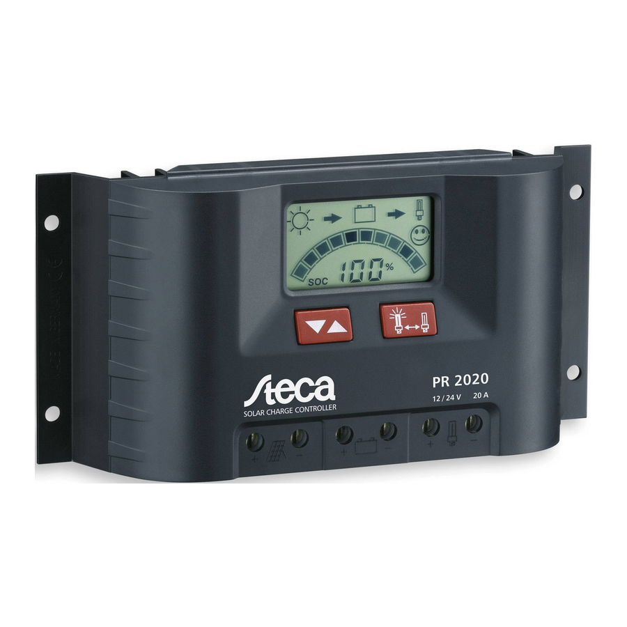
4. Operating the system regulator The display shows a variety of system data by symbols and digits. Both buttons control all settings and display windows. 4.1. Display and Operation Elements Display window for system information and messages Button for switching ... -
Page 8: Module Current
4.2.3. Module current Displays the actual produced solar module‘s current output. 4.2.4. Charging current Displays the charging current flowing into battery from the solar module. 4.2.5. Load current Displays the current drawn by the load output. 4.2.6. Ah – Battery charging meter Displays the accumulative sum of recharged Ah since the initial installation or reset. -
Page 9: Pwm Charge Control
Using this SOC information, you always have an accurate overview on the actual battery level. Using the SOC, the regulator also controls the selection of the charging procedure and the deep discharging protection in order to ideally maintain the battery. If one of the parameters cannot be recorded because for example, a consumer or charging source is directly connected to the battery, the SOC calculation is invalid. -
Page 10: Gel / Liquid Battery Type Setting
6.3. Gel / Liquid Battery Type Setting The standard setting is “Li”. The setting of the battery type influences the cutoff voltage of the controller. If you use a Gel or AGM battery, you have to change the battery type to GEL. Caution! An incorrect battery type setting can damage the battery! 6.4. -
Page 11: Serial Number Query
E) Start the auto-test with the left button. The test expires quickly and automatically. If there is no error, this window is displayed shortly (1. sec.) Afterwards, all LCD segments fade in and out for 1 second. Then the auto-test window reappears in the display. - Page 12 Display Meaning Cause / Remedy Excessive tempera- Let regulator cool. Check the ture regulator turned cause for overheating (installa- off the consumer tion site, other heat sources). due to internal over Possible reduce charge or load heating. current. Ensure the regulator has proper ventilation.
-
Page 13: Legal Guarantee
Display Meaning Cause / Remedy No battery connected Supply only by solar module. or connection inter- Connect battery to regulator rupted. and check battery fuse. Storage battery con- Disconnect battery and con- nected with reverse nect to regulator with correct polarity. -
Page 14: Technicel Data
Power consumption mA 12,5 mA PWM-Frequency 30 Hz Maximum input voltage < 47 V Minimum battery voltage 6.9 V Currents PR 1010 PR 1515 PR 2020 PR 3030 Max. continuous module 10 A 15 A 20 A 30 A current at 25 °C Max. - Page 15 Charge controller activation Activation threshold of the SOC Control Voltage control charge type Float charge SOC >=70 % >=12.7 V resp. >= 25.4 V Boost charge 11.7 V - 12.4 V; resp. 40 % - 69 % 23.4 V - 24.8 V Equalization charge SOC <...
Need help?
Do you have a question about the PR 1010 and is the answer not in the manual?
Questions and answers
Before I changed my batteries the controller showed 100 percent ,after installation it showed 30 percent
The Steca PR 1010 controller shows 30 percent after changing the batteries because most types of batteries should not reach state of charge values below 30%. This prevents dangerous deep discharges that could damage or shorten the battery’s lifespan. The controller likely sets the state of charge to 30% as a precautionary measure to avoid incorrect readings due to factors like battery age, temperature, and history.
This answer is automatically generated