Sign In
Upload
Download
Table of Contents
Contents
Add to my manuals
Delete from my manuals
Share
URL of this page:
HTML Link:
Bookmark this page
Add
Manual will be automatically added to "My Manuals"
Print this page
×
Bookmark added
×
Added to my manuals
Manuals
Brands
Steca Manuals
Controller
Power Tarom 2070
Installation and operation instruction manual
Steca Power Tarom 2070 Installation And Operation Instruction Manual
System manager for photovoltaic systemes
Hide thumbs
1
Table Of Contents
2
3
4
5
6
7
8
9
10
11
12
13
14
15
16
17
18
19
20
21
22
23
24
25
26
27
28
page
of
28
Go
/
28
Contents
Table of Contents
Bookmarks
Table of Contents
Table of Contents
1 Safety Instructions and Waiver of Liability
Symbol of Safety Instructions
How to Use this Manual
General Safety Instructions
Waiver of Liability
2 Quick Installation Instructions
3 Application Range
Power Range
Options
4 Functioning
General Description
Detailed Description
5 Indication of Status
Lc-Display
Alarm Contact
6 Operating the System-Manager
Factory Pre-Set Configurations
Main Menu
Menu Manu
Menu Logg
Menu Conf
Menu Prog
Example of Configuration
Example of Programming
7 Installation
Precautions
Location of Installation
Preparations
Installation and Operation
Uninstalling
Safety Measures
8 Overvoltage Protection in Your Photovoltaic System
9 Grounding
Positive Grounding
Negative Grounding
10 Hints for the Usage of Multiple Powertaroms
11 Maintenance
12 Technical Data
Performance Data
Regulation Data
13 Malfunctions and Errors
14 Legal Guarantee
15 Accessories
Advertisement
Quick Links
1
Safety Instructions and Waiver of Liability
2
Quick Installation Instructions
3
Power Range
4
Installation
5
Installation and Operation
Download this manual
PHOTOVOLTAIK - PHOTOVOLTAIC - PHOTOVOLTAIQUE - FOTOVOLTAICA
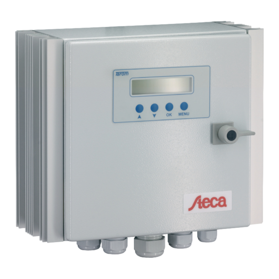
Installation and Operation Instruction Manual
System Manager for Photovoltaic systemes
Power Tarom
Tarom 2070, Tarom 2140, Tarom 4055, Tarom 4110, Tarom 4140
EN
09.47
Table of
Contents
Previous
Page
Next
Page
1
2
3
4
5
Advertisement
Table of Contents
Need help?
Do you have a question about the Power Tarom 2070 and is the answer not in the manual?
Ask a question
Questions and answers
Related Manuals for Steca Power Tarom 2070
Controller Steca Tarom 4545 Installation And Operating Instructions Manual
Solar charge controller (82 pages)
Controller Steca Tarom 4545 Installation And Operating Instructions Manual
Solar charge controller (77 pages)
Controller Steca Tarom 4545 Installation And Operating Instructions Manual
Solar charge controller adjustable, for hybrid and telecommunication systems (88 pages)
Controller Steca Tarom 4545 Installation Manual
Charge controller with 3g streambbox (7 pages)
Controller Steca Tarom 4545 Manual
Charge controller (6 pages)
Controller Steca Power Tarom 2140 Installation And Operation Instruction Manual
System manager for photovoltaic systemes (28 pages)
Controller Steca Power Tarom 4140 Installation And Operation Instruction Manual
System manager for photovoltaic systemes (28 pages)
Controller Steca TR A301 Installation And Operating Instructions Manual
Temperature difference controller (48 pages)
Controller Steca TR 0704 Installation And Operating Manual
System regulator for solar thermal systems 7 inputs, 4 outputs (84 pages)
Controller Steca TR A503 TTR U Installation And Operating Instructions Manual
Temperature differential controller with integrated data logger (60 pages)
Controller Steca Solarix MPPT 2010 Installation And Operating Instruction
Solar charge controller (20 pages)
Controller Steca PR 1010 Operating Instructions Manual
Solar charge controller 10 a / 15 a / 20 a / 30 a (20 pages)
Controller Steca PR 1010 Operating Instructions Manual
Solar charge controller 10 a / 15 a / 20 a / 30 a (15 pages)
Controller Steca Solsum 6.6F Operating Manual
Solsum f series. solar charge controller (2 pages)
Steca Solsum F, 6.6F, 8.8F, 10.10F - Controller Manual
(article)
Controller Steca Suntana Instructions For Installation And Operation Manual
System controller for thermal solar systems (25 pages)
This manual is also suitable for:
Power tarom 2140
Power tarom 4055
Power tarom 4140
Power tarom 4110
Table of Contents
Print
Rename the bookmark
Delete bookmark?
Delete from my manuals?
Login
Sign In
OR
Sign in with Facebook
Sign in with Google
Upload manual
Upload from disk
Upload from URL


Need help?
Do you have a question about the Power Tarom 2070 and is the answer not in the manual?
Questions and answers